What Is the Function of a Potentiometer?
In the intricate world of electronic components, the potentiometer stands out for its versatility and precision in controlling various parameters within a circuit. This fundamental component, integral to both amateur and professional electronic setups, allows for the adjustment of resistance, thus influencing current flow, signal level, and operational characteristics of a wide array of devices. Potentiometers are found everywhere from household dimmers and audio equipment to complex industrial machinery, so we need to understand their basic concepts, structures, and types. In this article, we delve into the nuances of potentiometers—examining their construction, types, application-specific designs, and critical considerations for selection and usage to harness their full potential effectively.Catalog
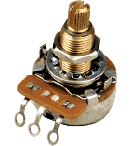
Figure 1: Potentiometer
Basic Concept of a Potentiometer
A potentiometer is a common component in electronic circuits, primarily used as an adjustable resistor. It is favored in various applications due to its ease of adjustment. Essentially, a potentiometer controls the flow of electric current by allowing users to change its resistance value, thereby precisely managing different parameters within a circuit. For instance, it can adjust the volume in audio devices or the brightness in home lighting systems.
The fundamental structure of a potentiometer consists of a resistive element made from materials like carbon or metal, and a movable wiper, also known as a slider. Adjusting a potentiometer typically involves rotating or sliding this wiper across the resistive material. This movement alters the position of the wiper, changing the amount of current passing through that section and thus modifying the circuit's overall resistance.
Potentiometers with three pins often use the middle pin to connect to the wiper, while the outer pins attach to either end of the resistive element. In many setups, this configuration allows the potentiometer to act as a voltage divider, distributing voltage based on the position of the wiper. However, for simple resistance adjustments, only the middle pin and one outer pin are used, putting the potentiometer in a variable resistor mode.
When selecting a potentiometer for practical applications, considerations like voltage tolerance and power rating are important to ensure it operates safely and reliably under specific circuit conditions. The physical design of the potentiometer must suit its operating environment. For example, in high-temperature or humid conditions, materials resistant to heat or moisture may be necessary to enhance durability and reliability.
Potentiometers combine technicality and practicality, making them a top choice for electronic designers and engineers when creating circuits. Whether for precise electrical measurements in labs or interactive user interfaces in consumer electronics, potentiometers offer a simple yet effective solution. Understanding their operating principles and structural characteristics can significantly improve their utilization to meet specific technical requirements and functionality expectations.
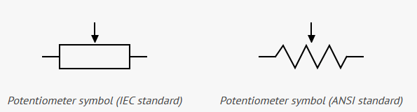
Figure 2: Potentiometer symbols
Structure of Potentiometer
The manufacturing process of a potentiometer is detailed and demands high technical precision, involving several steps designed to ensure the functionality and reliability of the final product. Initially, the process begins with selecting the right resistive material. This selection might include carbon composites, metal films, or conductive plastics. These materials determine the potentiometer’s resistance range, accuracy, and ability to withstand environmental factors like temperature, humidity, and physical wear.
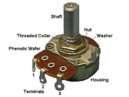
Figure 3: External Introduction of Potentiometer
The core structure of a potentiometer includes a strip-like conductor covered with a uniform layer of resistive material. This strip is typically made from highly conductive materials such as copper or aluminum to ensure smooth passage of current. The process of applying the resistive material must be precise to ensure that the resistance along the strip is uniform and reliable. The thickness and evenness of the coating are vital for the potentiometer’s performance, making the monitoring and control of this coating process stringent. These pins not only provide connection points to the external circuit but also support the overall stability of the structure. The central pin connects to a movable wiper, the critical component of the potentiometer’s adjustment mechanism. Made from soft yet durable materials like graphite or a metal alloy, the wiper slides across the resistive strip without damaging it.
The design of the wiper must make precise and reliable contact with the resistive strip. Users adjust the resistance by turning a knob or sliding the wiper, changing the contact point along the strip. This adjustment alters the resistance across the wiper section, thereby modifying the overall resistance in the circuit. A well-designed wiper not only ensures smooth and precise adjustments but also extends the lifespan of the potentiometer by preventing excessive wear that could lead to functional failure.
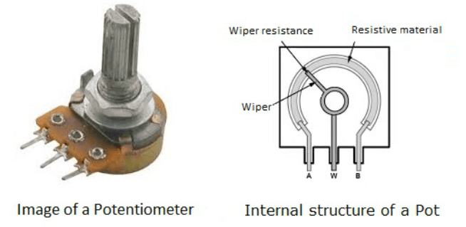
Figure 4: Internal Structure of Potentiometer
The assembly of potentiometers takes place on highly automated production lines that ensure each component is accurately installed for consistency. After assembly, each potentiometer undergoes rigorous testing for resistance accuracy, durability, and environmental adaptability to guarantee optimal performance in its application setting. Through this meticulous manufacturing process, potentiometers efficiently serve as variable resistors or voltage dividers in circuits, offering reliable adjustment capabilities for current or voltage.
Types of Potentiometers
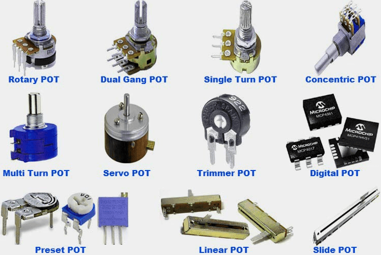
Figure 5: Types of Potentiometers
Potentiometers are indispensable components in electronic circuits, with various types designed for specific applications. These components are categorized based on their operational methods and application requirements, each offering unique features and benefits.
Rotary Potentiometers
Rotary Potentiometers are the most common type. They are simple in design and widely used in consumer electronics. Users adjust resistance values by rotating a knob, directly controlling parameters like volume or brightness. This knob typically turns clockwise or counterclockwise, allowing users to increase or decrease resistance, thus altering the current flowing through the potentiometer. Rotary potentiometers are ideal for audio equipment such as amplifiers and receivers because they offer smooth, continuous adjustments that minimally affect sound quality.
Dual-Gang Potentiometers
Dual-gang potentiometers are designed to control two separate audio channels simultaneously, commonly used in stereo audio systems. They ensure synchronized volume adjustments of left and right audio channels to maintain balanced output. This synchronization is achieved by assembling two sets of resistive tracks and sliding contacts within the same mechanical structure, allowing the adjustment knobs on both sides to move in unison, thus maintaining consistency between the channels.
Slide Potentiometers
Slide Potentiometers operate through a linear sliding motion, making them suitable for space-constrained applications like audio mixers and lighting consoles. Unlike rotary potentiometers, slide potentiometers have a straight operational trajectory, which provides users with precise control over resistance changes. These potentiometers are often found in professional audio equipment where rapid and accurate adjustments are crucial, as the visual slide path helps users gauge the adjustment level directly.
Trimmer Potentiometers
Trimmer Potentiometers are engineered for high-precision resistance adjustments. They are typically small and require a screwdriver or specialized tool for adjustments, making them perfect for use in laboratories and precision instruments where minor changes in resistance can significantly impact overall system performance.
Digital Potentiometers
Digital Potentiometers represent the modern evolution of potentiometer technology, operating through digital signals instead of mechanical movements. These potentiometers adjust resistance values by receiving digital codes (such as SPI or I2C protocols), making them well-suited for complex electronic systems that require programmable control. Digital potentiometers offer remote control capabilities and higher precision, increasingly finding applications in automated equipment and high-end consumer electronics.
By understanding the operational nuances and specific applications of these different types of potentiometers, users can better integrate them into electronic systems to achieve desired outcomes effectively.
How to Choose a Potentiometer?
A potentiometer, commonly referred to as a POT, essentially serves as a variable resistor, where adjustments are made through a knob positioned on its top. These devices are categorized by two primary attributes: resistance, measured in ohms (R), and power capacity, measured in watts (P).
The resistance value dictates the level of opposition it provides to electric current, a higher resistance results in less current flow. Common resistance values for potentiometers include 500Ω, 1K, 2K, 5K, 10K, 22K, 47K, 50K, 100K, 220K, 470K, 500K, and 1M. The power rating of a potentiometer indicates the amount of current it can safely handle. Typically, a potentiometer with a 0.3W rating is adequate for low-current circuits.
Key Factors for Selection
Resistance Value: It's crucial to select a potentiometer whose resistance matches the needs of your circuit. Potentiometers come in a vast range of sizes and shapes, from a few ohms to several megaohms.
Tolerance: This factor reflects the ability to maintain consistent resistance levels and is expressed as a percentage. A lower tolerance percentage means a more precise reading. If your application requires exact resistance values, opt for potentiometers with lower tolerance levels.
Rated Power: When choosing a potentiometer, consider its rated power, which shows how much wattage the component can handle without overheating or failing. Select a potentiometer with an adequate power rating to meet the energy demands of your specific circuit.
Type of Potentiometer: Select the type that best fits your application. Linear potentiometers are suitable for applications requiring a linear response, such as volume or tone controls. Logarithmic potentiometers are ideal for audio applications where volume changes are perceived logarithmically by the human ear. Multi-turn potentiometers are great for precise calibration, while digital potentiometers are suited for digital signal processing.
Physical Size: The size of the potentiometer is particularly important in space-constrained environments. Ensure the potentiometer you choose fits the available space in your project or application.
Mounting Type: Potentiometers come with different mounting options, such as panel mount, PCB mount, or through-hole mount. Choose one that is compatible with your circuit board or housing.
How to Use a Potentiometer?
When using a potentiometer, understanding the functions of its three terminals is key. Unlike ordinary two-terminal resistors, the third terminal of a potentiometer provides additional functionality, allowing it to play a more complex role in a circuit than just a traditional fixed resistor.
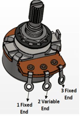
Figure 6: Three Terminals of Potentiometer
The potentiometer consists of two fixed terminals (marked 1 and 3) and an adjustable center terminal (marked 2). The fixed terminals are connected to the resistive material of the potentiometer, while the middle terminal is connected to a movable slider or wiper. This slider is free to move along the resistive material, thereby changing the length of the resistive path to the middle terminal.
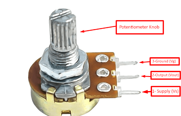
Figure 7: Potentiometer
As an example, consider a standard 10kΩ potentiometer. Without taking into account the middle terminals, the measurement from terminal 1 to terminal 3 should be 10kΩ, representing the full-length resistance of the potentiometer. When the middle terminal is enabled, if the slider is set at 25% from terminal 1, the resistance from terminal 1 to terminal 2 will be reduced to 25% of the total resistance, which is 2.5kΩ; accordingly, the resistance from terminal 2 to terminal 3 Then it is the remaining 75%, which is 7.5kΩ.
The position of the middle terminal can be flexibly adjusted by turning the knob located on the top of the potentiometer. This adjustment method provides the user with fine control over the resistance value and is ideal for applications that require fine adjustment of current intensity, such as volume control or light brightness adjustment. This flexibility makes potentiometers an integral part of regulating the functionality of a device.
This adjustable feature of the potentiometer is particularly important during the electronic prototyping and testing stages. By changing the position of the slider, designers can test the effect of different resistor values on circuit behavior without having to replace resistors. This not only improves the efficiency of testing but also greatly improves the flexibility and iteration speed of circuit design.
The Function of Potentiometer
Potentiometers play a pivotal role in circuit design, primarily serving as variable resistors or voltage dividers. These applications rely on their ability to adjust resistance values, enabling precise control over the current or voltage within a circuit. Consider a standard 10kΩ potentiometer, which can adjust its resistance from 0Ω up to 10kΩ, offering high flexibility to meet diverse circuit requirements.
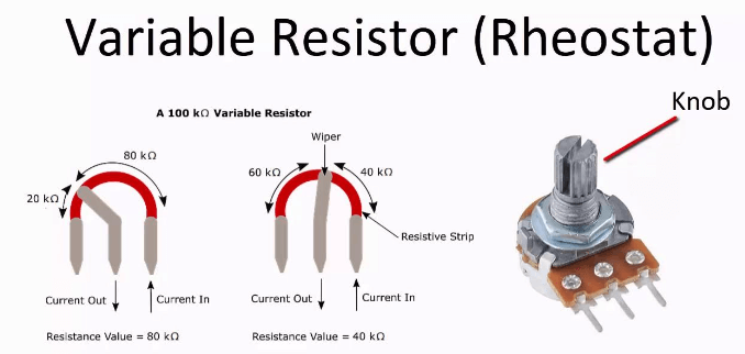
Figure 8: Potentiometer as a Variable Resistor
Variable Resistor
When used as a variable resistor, a potentiometer modifies the flow of current by continuously adjusting the resistance between its two ends. In this setup, one end of the potentiometer is connected to the power source, and the other to a load, such as a motor or light bulb. The third terminal, usually a sliding contact or wiper, moves according to the user's adjustments, changing its connection point with the power source or load. This manipulation allows users to manually regulate the current flowing through the load, controlling operational aspects such as motor speed or light brightness.
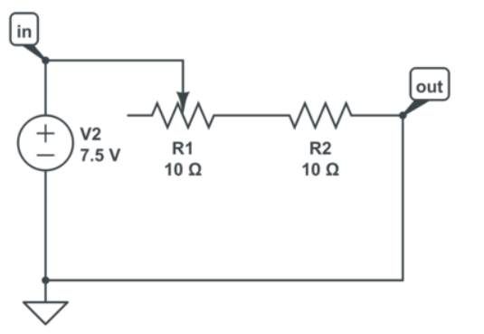
Figure 9: Potentiometer as a Voltage Divider
Voltage Divider
On the other hand, when serving as a voltage divider, the potentiometer's role is to split the input voltage to provide a variable output voltage. This is achieved by configuring the potentiometer as a voltage distributor, where the input voltage is applied across the two ends of the potentiometer, and the output voltage is taken from between the sliding contact and one of the fixed ends. This configuration enables the potentiometer to deliver any intermediate voltage level from zero volts up to the maximum input voltage, which is particularly useful in adjusting signal levels in audio processing and signal amplification.
Potentiometer Taper
The choice of taper in a potentiometer directly influences the response curve of resistance adjustments, thereby affecting the circuit's overall performance and user interaction. Taper essentially describes how the resistance value changes as the potentiometer is turned or slid. This change is graphically represented by a relationship curve between the potentiometer's output and its mechanical position, typically categorized into linear and logarithmic types.
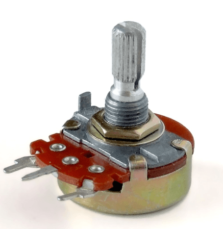
Figure 10: Linear Taper Potentiometers
Linear taper potentiometers ensure that the increase or decrease in resistance is uniform throughout its range of operation. That is, as you rotate or slide the control of the potentiometer, the resistance changes in a linear proportion. For instance, if the potentiometer is turned to 50% of its range, the resistance reaches 50% of its maximum value. This characteristic makes linear taper potentiometers well-suited for applications requiring precise voltage or current control, such as finely tuning input/output signals in testing and measurement equipment or steadily adjusting output in power supplies.
Figure 11: Logarithmic Taper Potentiometers
Logarithmic taper potentiometers, on the other hand, follow a non-linear adjustment curve, typically exponential, which means the resistance changes slowly at the start of the adjustment and more quickly toward the end. This pattern is particularly advantageous for audio control applications, as the human ear perceives sound levels logarithmically. The use of a logarithmic potentiometer in volume control allows for a more natural adjustment of sound volume, making the increase or decrease in volume appear more balanced and smoother, rather than abrupt.
Understanding the working principles and application scenarios of different taper potentiometers is crucial for the design of electronic devices. Choosing the correct taper type is not just about matching technical specifications; it also involves enhancing the end-user's interaction experience with the product. For instance, in user interface design, employing a logarithmic potentiometer to adjust background lighting or screen brightness results in a more intuitive and comfortable user experience, as this adjustment method more closely aligns with the human eye's perception of brightness changes.
Potentiometer Wiring Example
When wiring a potentiometer, your approach will depend on how you plan to use it. Typically, the middle pin is the wiper. Rotating the shaft to the right (or moving the slider) reduces the resistance between the wiper and the right pin. Moving it to the left decreases the resistance between the wiper and the left pin. Sometimes it makes sense to use all three pins, but at other times, you might only need two. Let's explore some examples.
Example 1: Potentiometer as a Simple Variable Resistor
If you need a simple resistor where you can adjust the resistance, you only need two pins: the middle pin and one of the side pins. Here's how you might connect a potentiometer to dim a Light-emitting diode (LED). In practical circuits, you might need to add a series resistor to ensure that adjusting the resistance to zero won't damage the LED. Rotating the shaft in one direction increases resistance, dimming the LED; turning it the other way decreases resistance, making the LED brighter.
Example 2: Connecting the Third Pin to the Middle
Sometimes, you might see a circuit diagram where the middle and one of the side pins are connected at the same point. Why is this done? This type of connection essentially uses just two pins since connecting the third pin to the middle one doesn't affect the resistance. Some people prefer this method because it tidies up the circuit by eliminating an unused pin, which can also make the schematic look cleaner and more organized.
Example 3: Potentiometer as Volume Control
In this example, all three pins of the potentiometer are used to create a simple way to adjust the volume of an audio amplifier. By connecting it this way, you create a voltage divider that can lower the voltage of the input signal. The more you turn the shaft, the more the volume decreases. This type of wiring is common in audio equipment.
Each of these wiring setups demonstrates how adjusting the potentiometer’s connections can tailor its functionality to specific applications, from simple lighting controls to more complex audio systems. Understanding how to manipulate these connections allows for greater flexibility and precision in electronic circuit design.
Troubleshooting Potentiometer Wiring
Troubleshooting potentiometer wiring issues is crucial when dealing with malfunctions that can affect the performance of your circuits and potentially damage your devices. To effectively diagnose and resolve these issues, a comprehensive examination of the potentiometer and its connections is necessary.
Checking Connection Tightness
A critical first step is to inspect the tightness of the potentiometer's connections. Loose wiring can lead to unstable resistance values, which in turn impacts the circuit's output. For instance, in a volume control circuit, loose connections might cause unwanted noise or sudden jumps in volume when adjusting. To check for loose connections, gently wiggle the wires and the pins of the potentiometer and observe any signs of looseness. If any loose connections are found, they should be securely reattached using the appropriate tools, such as a soldering iron.
Identifying Short Circuits
Next, check for any short circuits in the circuit. Shorts may occur due to improper wiring or internal damage to the potentiometer, creating an unintended electrical connection between two points that should not be directly connected. A short circuit can lead to abnormally high current flow, which can not only disrupt the functionality of the circuit but also risk overheating and potentially burning out the potentiometer or other electronic components. Using a multimeter set to measure resistance can help detect potential short circuits by checking the resistance values in different parts of the circuit.
Inspecting the Potentiometer and Surrounding Components
Finally, it is vital to inspect the potentiometer itself and the components around it. Damage to the potentiometer can occur due to mechanical wear, excessive current, or environmental factors like temperature and humidity. Testing whether the resistance changes smoothly as you adjust the potentiometer can indicate its condition. If the resistance changes discontinuously or does not respond during adjustment, it may suggest that the movable parts of the potentiometer, such as the slider or knob, are worn out or damaged. Additionally, checking for signs of damage or abnormal conditions in electronic components near the potentiometer is also recommended, as these could be contributing to potentiometer issues indirectly.
By following these steps, you can effectively diagnose and resolve issues related to potentiometer wiring and functionality, ensuring the stability and safety of your circuits. Continuous observation and meticulous handling are key during troubleshooting, while patience and a systematic approach to problem-solving can significantly enhance your efficiency in resolving these issues.
Conclusion
The role of the potentiometer in modern electronics cannot be overstated. Its ability to function as both a variable resistor and a voltage divider makes it indispensable in creating adaptable and efficient electronic circuits. Whether adjusting the volume on an audio device, calibrating signal levels in a testing setup, or fine-tuning the brightness of LEDs, the potentiometer remains a cornerstone of electronic design. Its versatility is matched by the need for precise selection and application, ensuring that each potentiometer not only meets the technical demands of the circuit but also enhances the user's interaction with the device. By embracing the insights and detailed analyzes of potentiometer functions, one can significantly improve the performance and reliability of electronic projects, paving the way for innovations that continue to push the boundaries of what is possible with simple yet effective electronic components.
Frequently Asked Questions [FAQ]
1. What is a potentiometer used for?
A potentiometer is primarily used to adjust the resistance within an electronic circuit. This allows it to control various parameters like volume on audio equipment, brightness on lighting systems, and general adjustment of signal levels.
2. How to test a potentiometer?
To test a potentiometer, you’ll need a multimeter set to the resistance measurement mode. Connect the multimeter’s probes to the terminal pins of the potentiometer (typically the outer pins). Rotate the potentiometer knob or slide throughout its range and observe the resistance value changes on the multimeter, ensuring they change smoothly and consistently.
3. Does a potentiometer control voltage or current?
A potentiometer can control both voltage and current indirectly by adjusting resistance. As a variable resistor, it primarily controls how much current flows through part of a circuit. Configured as a voltage divider, it can control the voltage output across its terminals.
4. How many volts can a potentiometer handle?
The voltage a potentiometer can handle depends on its specific design and rating. Common potentiometers in electronics usually handle between 3 to 50 volts, but it is essential to check the manufacturer’s specifications for the exact voltage rating to prevent damage and ensure safe operation.
5. How many wires are used on a potentiometer?
A potentiometer typically has three terminals or wires. One wire connects to each end of the resistive element, and the third connects to the movable wiper, which adjusts the resistance value by changing its position along the resistive track.
About us
ALLELCO LIMITED
Read more
Quick inquiry
Please send an inquiry, we will respond immediately.

What Happens If You Disconnect Throttle Position Sensor
on May 9th
NMOS and PMOS Guide - How it Works, Pros and Cons, Applications, Truth Tables, Comparison of the Two
on May 8th
Popular Posts
-

What is GND in the circuit?
on January 1th 3259
-

RJ-45 Connector Guide: RJ-45 Connector Color Codes, Wiring Schemes, R-J45 Applications, RJ-45 Datasheets
on January 1th 2806
-

Understanding Power Supply Voltages in Electronics VCC, VDD, VEE, VSS, and GND
on November 20th 2620
-

Fiber Connector Types: SC Vs LC And LC Vs MTP
on January 1th 2253
-

Comparison Between DB9 and RS232
on January 1th 1869
-

What Is An LR44 Battery?
Electricity, that ubiquitous force, quietly permeates every aspect of our daily lives, from trivial gadgets to life-threatening medical equipment, it plays a silent role. However, truly grasping this energy, especially how to store and efficiently output it, is no easy task. It is against this background that this article will focus on a type of coin cell battery that may seem insignificant on the...on January 1th 1836
-

Understanding the Fundamentals:Inductance Resistance, andCapacitance
In the intricate dance of electrical engineering, a trio of fundamental elements takes center stage: inductance, resistance, and capacitance. Each bears unique traits that dictate the dynamic rhythms of electronic circuits. Here, we embark on a journey to decipher the complexities of these components, to uncover their distinct roles and practical uses within the vast electrical orchestra. Inductan...on January 1th 1791
-

What Is RF and Why Do We Use It?
Radio Frequency (RF) technology is a key part of modern wireless communication, enabling data transmission over long distances without physical connections. This article delves into the basics of RF, explaining how electromagnetic radiation (EMR) makes RF communication possible. We will explore the principles of EMR, the creation and control of RF signals, and their wide-ranging uses. The article ...on January 1th 1782
-

CR2430 Battery Comprehensive Guide: Specifications, Applications and Comparison to CR2032 Batteries
What is CR2430 battery ?Benefits of CR2430 BatteriesNormCR2430 Battery ApplicationsCR2430 EquivalentCR2430 VS CR2032Battery CR2430 SizeWhat to look for when buying the CR2430 and equivalentsData Sheet PDFFrequently Asked Questions Batteries are the heart of small electronic devices. Among the many types available, coin cells play a crucial role, commonly found in calculators, remote controls, and ...on January 1th 1781
-

Comprehensive guide to hFE in transistors
Transistors are crucial components in modern electronic devices, enabling signal amplification and control. This article delves into the knowledge surrounding hFE, including how to select a transistor's hFE value, how to find hFE, and the gain of different types of transistors. Through our exploration of hFE, we gain a deeper understanding of how transistors work and their role in electronic circu...on November 20th 1769
HOT Part Number
-

FDD8586
Fairchild Semiconductor
MOSFET N-CH 20V 35A TO252AA
UPD70F3740GC-UEU-AX
Renesas Electronics America Inc
IC MCU 32BIT 512KB FLASH 100LQFP
TPD1S514-2YZR
Texas Instruments
IC USB CHARGER OVP 12DSBGA
MAX6604AATA+T
Analog Devices Inc./Maxim Integrated
IC TEMP SENSOR DDR MEMORY 8TDFN
12061A332JAT2A
AVX Corporation
CAP CER 3300PF 100V C0G/NP0 1206
B39941B9881P810
Qualcomm (RF front-end (RFFE) filters)
MOBILE SAW FILTER 1109
AT29C020-15JC
Microchip Technology
IC FLASH 2MBIT PARALLEL 32PLCC
PI6C557-03BLEX
Diodes Incorporated
IC CLOCK GENERATOR 16TSSOP
AD7533UQ
Analog Devices Inc.
IC DAC 10BIT A-OUT 16CDIP
SN74LVC3G17DCTR
Texas Instruments
IC BUFFER NON-INVERT 5.5V SM8
CY7C131-25NC
Infineon Technologies
IC SRAM 8KBIT 25NS 52QFP
VB40100G-E3/8W
Vishay General Semiconductor - Diodes Division
DIODE ARRAY SCHOTTKY 100V TO263
ADP3338AKC-3-RL
Analog Devices Inc.
IC REG LINEAR 3V 1A SOT223-3
M74HC573TTR
STMicroelectronics
IC LATCH OCTAL D 3STATE 20-TSSOP
MCR100JZHJ680
Rohm Semiconductor
RES SMD 68 OHM 5% 1W 2512
AD7690BCPZ-R2
Analog Devices Inc.
IC ADC 18BIT 10LFCSP
74LVT162244MTDX
onsemi
IC BUF NON-INVERT 3.6V 48TSSOP
1N2436
Microchip Technology
DIODE GEN PURP 50V 150A DO205AA -
FWP-175A
Eaton - Bussmann Electrical Division
FUSE CARTRIDGE 175A 700VAC/VDC
KSE13003TH1ATU
Fairchild Semiconductor
TRANS NPN 400V 1.5A TO220-3
GRM3195C1H133JA01D
Murata Electronics
CAP CER 0.013UF 50V C0G/NP0 1206
1259-7SDRSYGW/S530-A3
Everlight Electronics Co Ltd
LED RED/YLW-GREEN DIFF 3MM T/H
GRM31MR71E105KA01L
Murata Electronics
CAP CER 1UF 25V X7R 1206
B0430J50100AHF
TTM Technologies, Inc.
BALUN 400MHZ-3000MHZ 50/100 0805
AD5640BRJZ-1500RL7
Analog Devices Inc.
IC DAC 14BIT V-OUT SOT23-8
BLF8G38LS-75V
Ampleon USA Inc.
RF FET LDMOS 75V SOT1239B
BLM15AG221SN1D
Murata Electronics
FERRITE BEAD 220 OHM 0402 1LN
12065C473M4T2A
KYOCERA AVX
CAP CER 0.047UF 50V X7R 1206
MAX964EEE+T
Analog Devices Inc./Maxim Integrated
IC COMPARATOR 4 GEN PUR 16QSOP
MAX5035DASA
Analog Devices Inc./Maxim Integrated
IC REG BUCK ADJUSTABLE 1A 8SOIC
FCP190N65F
onsemi
MOSFET N-CH 650V 20.6A TO220-3
GRM0225C1E7R7BDAEL
Murata Electronics
CAP CER 7.7PF 25V C0G/NP0 01005
SPC18P8LM4H-1
Knowles
MIC MEMS DIGITAL PDM OMNI -26DB
FAN3227CMX-F085
onsemi
IC GATE DRVR LOW-SIDE 8SOIC
WP7-P024VA1-R6000
JAE Electronics
CONN PLUG 24POS SMD GOLD
HD49338HFEB-E
Renesas Electronics America Inc
PGA & 12-BIT A/D CONVERTER -

LTC3862EGN-1#PBF
Analog Devices Inc.
IC REG CTRLR BOOST/SEPIC 24SSOP
LM3676SD-1.8
Texas Instruments
IC REG BUCK 1.8V 600MA 8WSON
BCM56744A1KFRBLG
Broadcom Limited
MULTI LAYER SWITCH
KDZTR24B
Rohm Semiconductor
DIODE ZENER 25.3V 1W PMDU
AD5308BRU
Analog Devices Inc.
IC DAC 8BIT V-OUT 16TSSOP
ISL1557AIUEZ-T7
Renesas Electronics America Inc
IC TELECOM INTERFACE 10HMSOP
MMBZ5230BLT1
onsemi
DIODE ZENER 4.7V 225MW SOT23-3
TL1451ACPWRG4
Texas Instruments
IC REG CTRLR MULT TOP 16TSSOP
TPS53114PWR
Texas Instruments
IC REG CTRLR BUCK 16HTSSOP
MT29F8G08ABACAH4-IT:C
Micron Technology Inc.
IC FLASH 8GBIT PARALLEL 63VFBGA
1SMA70AT3G
onsemi
TVS DIODE 70VWM 113VC SMA
TLA2528IRTET
Texas Instruments
IC SOC PROCESSOR
IRFR24N10D
Vishay Siliconix
MOSFET N-CH 100V DPAK
BXB75-48S12FLTJ
Artesyn Embedded Power
DC DC CONVERTER 12V 75W
R5F51303ADFK#30
Renesas Electronics America Inc
IC MCU 32BIT 64KB FLASH 64LQFP
APX803S00-31SA-7
Diodes Incorporated
IC SUPERVISOR 1 CHANNEL SOT23
LNK584DG
Power Integrations
IC OFFLINE SWITCH FLYBACK 8SO
HFA1113MJ/883
Harris Corporation
IC BUFFER 1 CIRCUIT 8CERDIP