Comprehensive guide to hFE in transistors
Catalog
What is hFE in a Transistor?
How to Calculate a Transistor's hFE?
The Importance of hFE in Transistors
How to Find a Transistor's hFE?
Different Types of Transistor Gain
What is the hFE Value of a Transistor?
Specifications of hfe
Different States of Current Gain
Factors Affecting hfe
hfe and Beta β
Conclusion
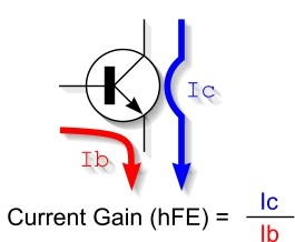
What is hFE in a Transistor?
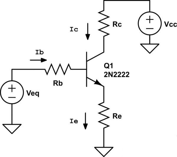
How to Calculate a Transistor's hFE?
Typically, you would follow these steps:
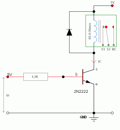
1. Prepare the Circuit
2. Measure Base Current (Ib)
3. Measure Collector Current (Ic)
4. Calculate the hFE Value
Considerations
The Importance of hFE in Transistors
How to Find a Transistor's hFE?
Different Types of Transistor Gain
Two Forms of Current Gain
Beta (β) or hFE:
he:
Other Important Types of Gain
Alpha (α):
Voltage Gain (Av):
Power Gain (Ap):
What is the hFE Value of a Transistor?
Specifications of the
- - Definition: Common-emitter amplification factor, representing the ratio of transistor collector current to base current (hFE = IC/IB)
- - Typical Range: Applies to 10 to 500 times, with most values at 100
- - Variability: There can be significant differences between transistors of the same type
- - Temperature Stability: Affected by temperature, hFE decreases with rising temperature
- - Current Stability: Allows collector current to vary without increasing significantly with collector current
- - Gain Error: For bipolar transistor gain, deviations and offsets are important for device performance
- - Environmental Stability: Used for a large number of transistors, where transistor hFE can have a significant effect
- - Natural Attenuation: In small current amplitudes, natural attenuation leads to a decrease in hFE value to ensure consistent performance
- - Usage in Circuits: Widely used in circuit design, for example, to determine stable electric in transistor collector-base circuits
Different States of Current Gain
1. Active Region (Linear Region)
2. Saturation Region
3. Cut-off Region
Factors Affecting the
How Temperature Affects hFE
The Impact of Collector Current Variation on hFE
Aging, Degradation, and Their Effects on hFE
he and Beta β
|
hallmark |
hFE
(ac gain exponent) |
Beta
(DC gain index) |
|
define |
Ratio
of collector current (Ic) to base current (Ib) |
Gain
static is greater than zero, reflecting the ratio between Ib and Ic. |
|
Other
names |
Residual
current gain, βF |
/ |
|
usage |
Commonly
used in common emitter mode |
/ |
|
realm |
Applicable
between 10 and 500 |
/ |
|
symbolize |
β |
hFE
(commonly used in place of β in BJT data sheets) |
|
sensitivities |
May
vary depending on operating conditions |
May
vary depending on operating conditions |
|
representation |
AC
current index |
DC
Current Gain |
|
significance |
Special
requirements for materials of an environmentally friendly nature |
/ |
Conclusion
Frequently Asked Questions
1.What is the current gain of a transistor?
2.How do you test whether the transistor is bad or good?
3.How do you measure a transistor with a multimeter?
About us
ALLELCO LIMITED
Read more
Quick inquiry
Please send an inquiry, we will respond immediately.
ULN2003 Comprehensive Guide - Features, Operating Principles, Equivalents and Applications
on April 10th
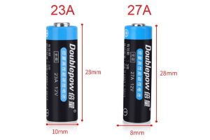
27A Battery VS 23A Battery: Different Sizes, Same Energy
on April 8th
Popular Posts
-

What is GND in the circuit?
on January 1th 3168
-

RJ-45 Connector Guide: RJ-45 Connector Color Codes, Wiring Schemes, R-J45 Applications, RJ-45 Datasheets
on January 1th 2739
-

Understanding Power Supply Voltages in Electronics VCC, VDD, VEE, VSS, and GND
on November 17th 2360
-

Fiber Connector Types: SC Vs LC And LC Vs MTP
on January 1th 2214
-

Comparison Between DB9 and RS232
on January 1th 1834
-

What Is An LR44 Battery?
Electricity, that ubiquitous force, quietly permeates every aspect of our daily lives, from trivial gadgets to life-threatening medical equipment, it plays a silent role. However, truly grasping this energy, especially how to store and efficiently output it, is no easy task. It is against this background that this article will focus on a type of coin cell battery that may seem insignificant on the...on January 1th 1806
-

Understanding the Fundamentals:Inductance Resistance, andCapacitance
In the intricate dance of electrical engineering, a trio of fundamental elements takes center stage: inductance, resistance, and capacitance. Each bears unique traits that dictate the dynamic rhythms of electronic circuits. Here, we embark on a journey to decipher the complexities of these components, to uncover their distinct roles and practical uses within the vast electrical orchestra. Inductan...on January 1th 1759
-

CR2430 Battery Comprehensive Guide: Specifications, Applications and Comparison to CR2032 Batteries
What is CR2430 battery ?Benefits of CR2430 BatteriesNormCR2430 Battery ApplicationsCR2430 EquivalentCR2430 VS CR2032Battery CR2430 SizeWhat to look for when buying the CR2430 and equivalentsData Sheet PDFFrequently Asked Questions Batteries are the heart of small electronic devices. Among the many types available, coin cells play a crucial role, commonly found in calculators, remote controls, and ...on January 1th 1725
-

What Is RF and Why Do We Use It?
Radio Frequency (RF) technology is a key part of modern wireless communication, enabling data transmission over long distances without physical connections. This article delves into the basics of RF, explaining how electromagnetic radiation (EMR) makes RF communication possible. We will explore the principles of EMR, the creation and control of RF signals, and their wide-ranging uses. The article ...on January 1th 1714
-

Comprehensive guide to hFE in transistors
Transistors are crucial components in modern electronic devices, enabling signal amplification and control. This article delves into the knowledge surrounding hFE, including how to select a transistor's hFE value, how to find hFE, and the gain of different types of transistors. Through our exploration of hFE, we gain a deeper understanding of how transistors work and their role in electronic circu...on November 17th 1684
HOT Part Number
-
DS90C032BTMX
Texas Instruments
IC RECEIVER 0/4 16SOIC
CY7C9235A-270JXC
Infineon Technologies
IC DIGITAL CONTROLLER 44PLCC
DS90UB913ATRTVRQ1
Texas Instruments
IC SER/DES 10-100MHZ FPD 32WQFN
LT1375IS8
Analog Devices Inc.
IC REG BUCK SEPIC ADJ 1.5A 8SOIC
1812AC223JAT1A
KYOCERA AVX
CAP CER 0.022UF 1KV X7R 1812
MP6513LGJ-Z
Monolithic Power Systems Inc.
IC MTR DRV BIPLR 2.5-5.5V TSOT23
08051C102K4T2A
KYOCERA AVX
CAP CER 1000PF 100V X7R 0805
MCF51JM32VLK
NXP USA Inc.
IC MCU 32BIT 32KB FLASH 80LQFP
742792034
Würth Elektronik
FERRITE BEAD 220 OHM 0805 1LN
AD5754RBREZ
Analog Devices Inc.
IC DAC 16BIT V-OUT 24TSSOP
TPS65235RUKR
Texas Instruments
IC REG CONV SATELLIT 1OUT 20WQFN
LQP03TG47NJ02D
Murata Electronics
FIXED IND 47NH 100MA 5.2 OHM SMD
AL6562S-13
Diodes Incorporated
IC LED DRIVER OFFL SWITCHER 8SO
SN761683DAR
Texas Instruments
IC VIDEO TUNER 32TSSOP
APTF1616QBDSURKCGKC
Kingbright
LED RGB CLEAR 4SMD
L9638D013TR
STMicroelectronics
IC TRANSCEIVER HALF 1/1 8SO
LPV358DGKRG4
Texas Instruments
IC OPAMP GP 2 CIRCUIT 8VSSOP
PCM3501E
Burr Brown
PCM3501 LOW VOLTAGE, LOW POWER, -

3006P-1-201LF
Bourns Inc.
TRIMMER 200OHM 0.75W PC PIN SIDE
ECH8320-TL-H
Fairchild Semiconductor
MOSFET P-CH 20V 9.5A SOT28FL
LM339QT
STMicroelectronics
IC COMPARATOR 4 GEN PUR 16QFN
EMK105BJ104KV-F
Taiyo Yuden
CAP CER 0.1UF 16V X5R 0402
LTM8045IY
Analog Devices Inc.
DC DC CONVERTER +/-2.5 +/-15V
BCR148WH6327
Infineon Technologies
BIPOLAR DIGITAL TRANSISTOR
TCR3DF33,LM
Toshiba Semiconductor and Storage
IC REG LINEAR 3.3V 300MA SMV
MBR20150CT
Yangzhou Yangjie Electronic Technology Co.,Ltd
SCHOTTKY DIODE 150V 20A TO-220AB
PCD1R5-24-1212
TDK-Lambda Americas Inc
DC DC CONVERTER +/-12V 1.44W
MKE02Z32VLD4
NXP USA Inc.
IC MCU 32BIT 32KB FLASH 44LQFP
MAX4610CUD+T
Analog Devices Inc./Maxim Integrated
IC SW SPST-NOX4 100OHM 14TSSOP
CY74FCT16244ATPACT
Cypress Semiconductor Corp
IC BUFF NON-INVERT 5.5V 48TSSOP
LT3008ETS8-5#TRPBF
Analog Devices Inc.
IC REG LINEAR 5V 20MA TSOT23-8
TLC7524CNSR
Texas Instruments
IC DAC 8BIT A-OUT 16SO
CA3420E
Intersil
IC OPAMP GP 1 CIRCUIT 8DIP
6718 BK005
Alpha Wire
HOOK-UP STRND 12AWG BLACK 100'
TDE3247FPT
STMicroelectronics
IC PWR DRIVER BIPOLAR 1:1 14SO
MLX91208LDC-CAH-000-SP
Melexis Technologies NV
SENSOR CURRENT HALL 20MT AC/DC -
ST16C654IQ64-F
MaxLinear, Inc.
IC UART FIFO 64B QUAD 64LQFP
UCC5696PN
Texas Instruments
IC PROG TERM SCSI 27LINE 80-LQFP
BU2630FV-E2
Rohm Semiconductor
IC PLL FREQ SYNTH 16SSOP
02016D225MAT2A
AVX Corporation
CAP CER 2.2UF 6.3V X5R 0201
EP3C10U256C6N
Intel
IC FPGA 182 I/O 256UBGA
C3216CH2E332J085AA
TDK Corporation
CAP CER 3300PF 250V CH 1206
LM385M-1.2
Texas Instruments
IC VREF SHNT -2.43%/+2.02% 8SOIC
DF30FC-50DS-0.4V(81)
Hirose Electric Co Ltd
CONN RCPT 50POS SMD GOLD
06035A331KAT4A
KYOCERA AVX
CAP CER 330PF 50V C0G/NP0 0603
RT0805DRE0710KL
Yageo
RES SMD 10K OHM 0.5% 1/8W 0805
PBSS5420D,115
Nexperia USA Inc.
TRANS PNP 20V 4A 6TSOP
PM30-24D12
TDK-Lambda Americas Inc
DC DC CONVERTER +/-12V 30W
F930J107MBA
KYOCERA AVX
CAP TANT 100UF 20% 6.3V 1411
SDA02H0SBD
C&K
SWITCH SLIDE DIP SPST 25MA 24V
FQA16N50
onsemi
MOSFET N-CH 500V 16A TO3P
OPA837IDCKR
Texas Instruments
IC OPAMP VFB 1 CIRCUIT SC70-5
MLG0603P2N8BT000
TDK Corporation
FIXED IND 2.8NH 500MA 200MOHM SM
GDZ8V2BLP3-7
Diodes Incorporated
DIODE ZENER 8.2V 250MW 2DFN