ULN2003 Comprehensive Guide - Features, Operating Principles, Equivalents and Applications
The ULN2003 series, known for integrating high voltage and high current capabilities in a Darlington transistor array, stands out for its advantageous working voltage, superior performance in current amplification, wide temperature adaptability, and load-bearing capacity. This makes it an ideal choice for many systems requiring high-power drives. This article aims to delve into the core characteristics of the ULN2003, covering its pin configuration, functional description, operational mechanisms, and practical applications in various scenarios. Let’s dive in for a detailed understanding.
Catalog
1. Overview of ULN2003
The ULN2003 is a high voltage, high current driver that has found its place in a wide array of applications, including controlling electronic locks, powering motors and stepper motors, driving LED displays, and managing devices in smart homes. This versatility stems from its precise capability to handle high voltage and current requirements. At its core, the ULN2003 consists of seven silicon NPN Darlington pairs. Each transistor is connected in series with a 2.7KΩ resistor, significantly enhancing its driving capability. One of the standout features of the ULN2003 is its compatibility with 5V operating voltage, enabling direct connections with TTL and CMOS circuits. This direct connection simplifies data processing that would otherwise require standard logic buffers, thus facilitating control over individual devices and enabling simultaneous operations across multiple devices.
Designed ingeniously, the ULN2003 produces an output voltage independent of the input voltage, seamlessly fitting into any circuit design, whether involving microcontrollers or microprocessor systems. It supports up to 50V load voltage and up to 500mA current. Its capacity can be extended beyond these limits by paralleling multiple output pins. Additionally, the ULN2003 comes with built-in features for frequency damping and back-EMF protection, adding an extra layer of safety for connected devices. This thoughtful design ensures that the ULN2003 not only meets the diverse needs of current high voltage, high current applications but also further guarantees reliability and safety.
2. Features of ULN2003
The ULN2003 boasts the following features:
- It can operate under voltages up to 50V (some versions can go up to 100V).
- It allows a current of up to 500 mA per input.
- Includes an internal clamp diode for device protection.
- Features internal protection for the return system, with a pin available for charge sensing.
- Perfect integration with microcontrollers and Arduino boards.
- Compatibility with TTL logic and 5v CMOS.
- The ULN2003 chip is available in 16-pin DIP, TSSOP, and SOIC packages.
- Commonly, it comes with additional components mounted on a module in the market for easier connection.
3. Pin Configuration of ULN2003
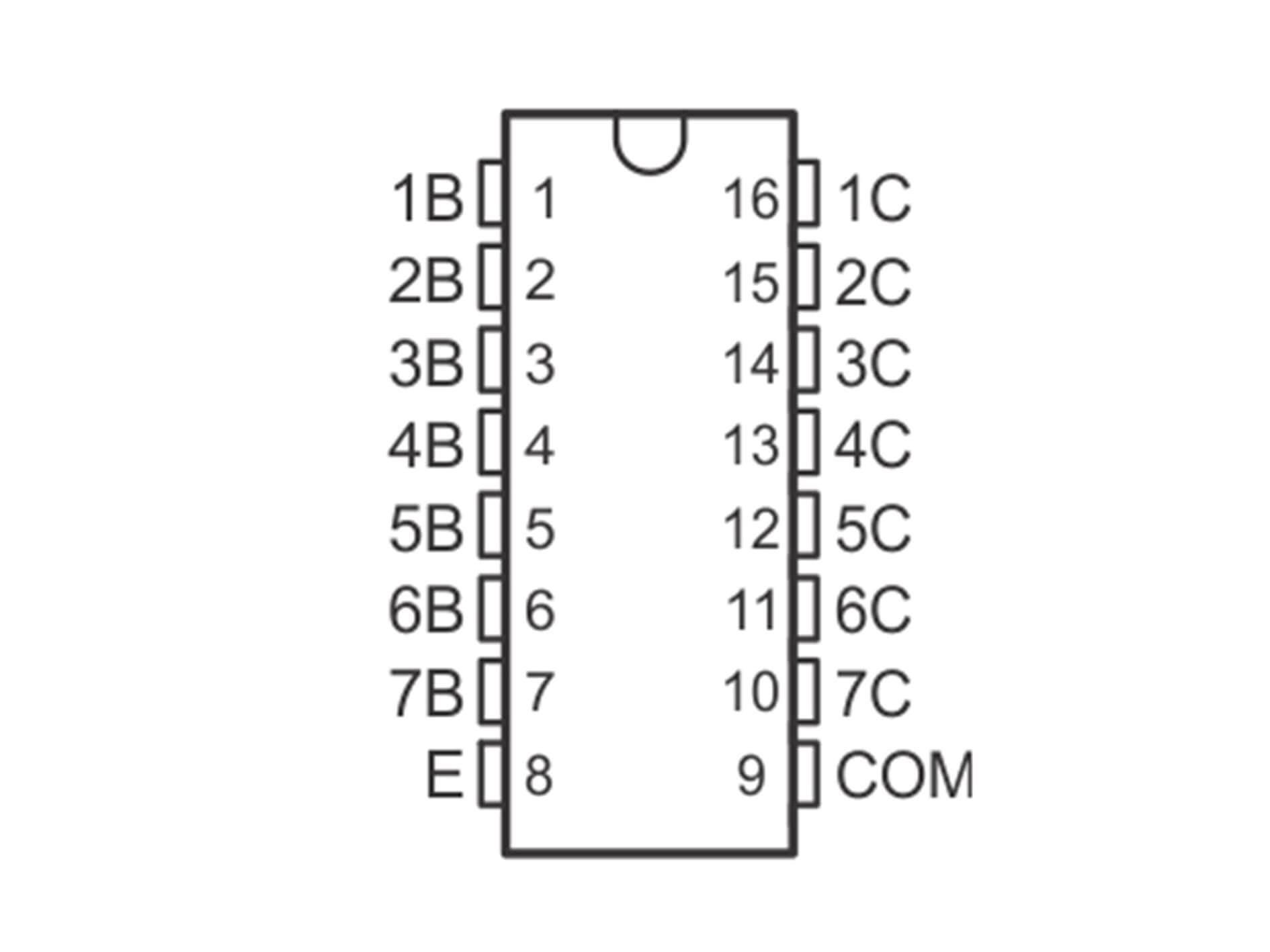
1. Input 1: This pin controls the corresponding output (Output 1). If it’s high (5V), there will be an output; otherwise, there will be none.
2. Input 2: Same as above, but affects Output 2.
3. Input 3: Same as above, for Output 3.
4. Input 4: Same for Output 4.
5. Input 5: Same as above, for Output 5.
6. Input 6: Same as above, but for Output 6.
7. Input 7: Same, but for Output 7.
8. GND: This pin 8 is for grounding, to be connected to the power supply.
9. COM: This pin can perform various functions. It’s typically used as a test pin to open all outputs. It can also be used for inductive loads.
10. Output 7: Controlled by Input 7, any load of 50V and 500mA can be connected to it.
11. Output 6: Same as above, but depends on Input 6.
12. Output 5: Same but corresponds to Input 5.
13. Output 4: Same as above, but controlled by Input 4.
14. Output 3: The same, but corresponds to Input 3.
15. Output 2: Same as above, but corresponds to Input 2.
16. Output 1: Controlled by Input 1, but has the same characteristics as the others.
4. Operating Principle and Functionality of ULN2003
The ULN2003 chip cleverly divides its functionality into two main parts: input and output. On one hand, it uses seven input pins (IN1 to IN7) to capture incoming logic signals. On the other, seven output transistors (OUT1 to OUT7) manage the on and off states of the loads they are connected to. The advantage of this setup is its responsiveness to signal changes: a high signal keeps the internal transistors in a closed state, preventing current from flowing to the load, while a low signal opens them, allowing current to flow freely. This direct link between the input pins' signals and the output pins' actions enables precise control over the connected devices.
Functionally, the ULN2003 is designed to drive loads that are too high in voltage, current, or inductance for standard microcontrollers to handle directly. Moreover, each of its outputs is equipped with clamp diodes, providing reverse protection and significantly enhancing the system’s stability and reliability. This design not only meets the high demands of controlling high-power loads but also ensures the safety of complex circuit configurations, making it a reliable choice for challenging electrical environments.
5. Driving a Stepper Motor with ULN2003
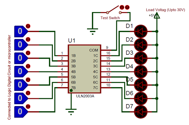
The ULN2003 is a 16-pin integrated circuit integrating seven pairs of Darlington transistors, each capable of driving loads up to 50V and 500mA. We are equipped with corresponding seven input and output pins for these seven Darlington pairs. Additionally, it includes a ground pin and a common pin. Normally, the ground pin is directly grounded, while the use of the common pin is optional. Surprisingly, this IC does not have a dedicated VCC pin. This is because the power needed for the transistors to work is taken directly from the input pins. Below is a simple circuit example that can be used to test the operation of the ULN2003 integrated circuit.
In this setup, an LED is considered the load, with its positive terminal connected to the power supply and its negative terminal grounded through an output pin of the ULN2003. This design is chosen because, when the voltage level at an input pin rises, the corresponding output pin grounds, thus closing the circuit and lighting the LED. Moreover, although the maximum load current limit for each output pin is 500mA, driving higher current loads can be achieved by paralleling multiple output pins. For instance, paralleling three pins can theoretically drive currents up to 1.5A. While grounding the COM pin is optional, it can be used as a test switch, enabling all output pins to ground when the COM pin is grounded.
6. Applications of ULN2003
- For driving high-current loads with digital circuits.
- Suitable for driving stepper motors.
- Can drive high-current LEDs.
- Relay drive modules (capable of driving 7 relays).
- Logic buffers in digital electronics.
- Used as a touch sensor for Arduino.
7. Equivalent ICs to ULN2003
- LR2003L
- TBD62003APG
- ULN2001
- ULN2001A
- ULN2003A
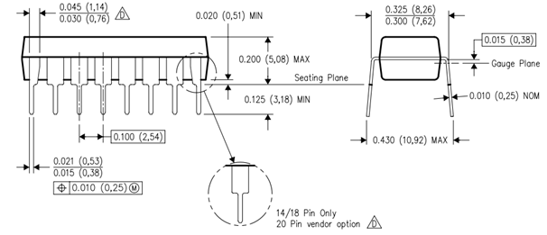
8. Model Diagram of ULN2003
Frequently Asked Questions [FAQ]
Q1. What is ULN2003 used for?
The ULN2003 Stepper Motor Drive module is utilized for driving stepper motors, high-current LEDs, and Relay Modules. This IC employs Darlington pairs for the output and can provide up to 5V and 500mA. The power needed for the transistors' operation is sourced from the control input, hence there is no Vcc pin on the IC.
Q2. What is the difference between ULN2003 and ULN2004?
The ULN2003A features a 2.7-kΩ series base resistor for each Darlington pair, enabling direct operation with TTL or 5-V CMOS devices. The ULN2004A has a 10.5-kΩ series base resistor to facilitate its direct operation from CMOS devices using supply voltages of 6 to 15 V.
Q3. What is the maximum voltage for ULN2003?
The ULN2003A, a popular component for driving higher voltage loads from logic, has its inputs rated for up to 30V and the outputs for up to 50V. The ULN2004 could also be considered as an alternative.
Q4. What is the difference between ULN2003 and ULQ2003?
These can all be considered different versions of the same device, namely ULN2003A. ULN2003A is a 7-channel low-side Darlington array. ULQ2003A is identical to ULN2003A but rated for higher temperatures (85°C). ULN2803 has 8 channels instead of 7, making it similar to ULN2003A.
Q5. Can ULN2003 be used to drive a stepper motor?
The primary function of the ULN2003 is to amplify the control signals from the Arduino so they can be used to drive the 28BYJ-48 Stepper Motor.