Photocouplers, Opto-couplers & Opto-isolators Explained
In the world of electronics, it's really important to make sure that signals can move smoothly and safely from one circuit to another, especially when these circuits work with different voltage levels or are affected by electrical noise. Photocouplers, which are also called optocouplers or opto-isolators, help make this happen. These small devices use light to send signals between circuits while keeping them separate, which helps protect sensitive parts from damage. In this article, we'll explore how photocouplers work, where they're used, and why they are so useful in electronics today.Catalog
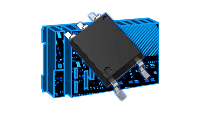
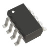
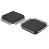
Figure 1: Photocoupler Component
Understanding Photocouplers
Photocouplers, also called optocouplers or optoisolators, are devices that allow signals to pass from one electrical circuit to another while keeping them separate from each other. The main job of a photocoupler is to make sure that signals from one circuit don’t interfere with another, especially when the circuits have different voltage levels or when one circuit might have electrical noise. This separation is done using light, so the signal can be passed on without a direct electrical connection.
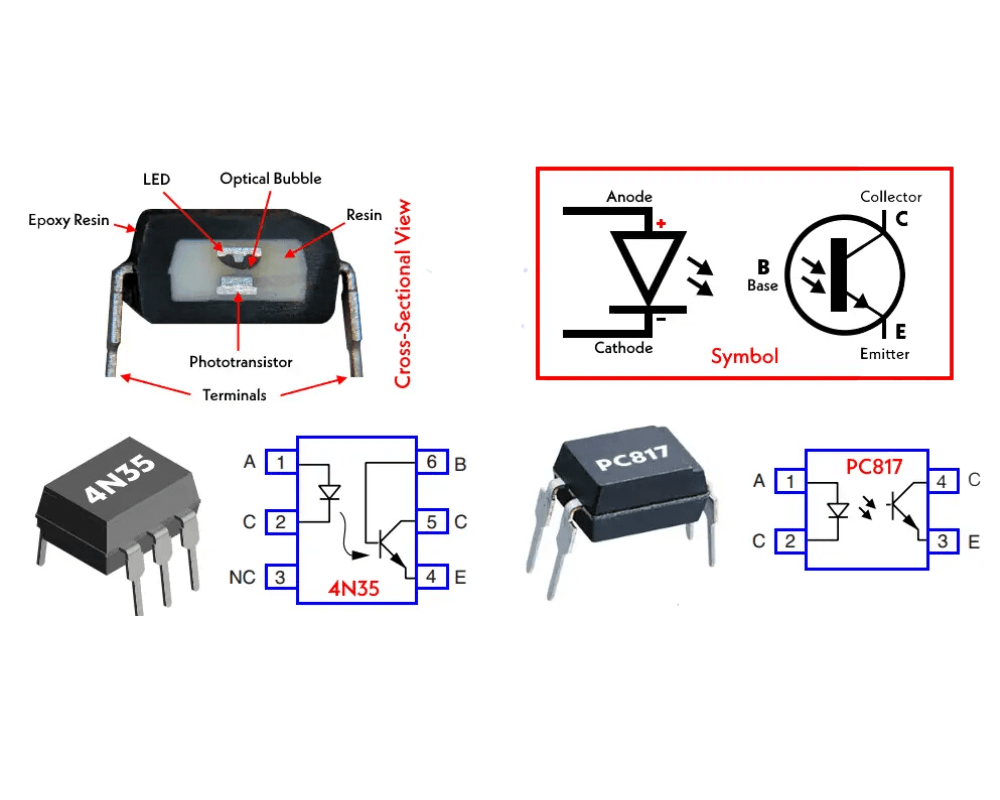
Figure 2: Cross-Sectional View and Symbol of a Photocoupler
Parts of a Photocoupler
A photocoupler has two main parts:
Light Emitting Diode (LED): The first part is the LED, which is on the input side. This LED takes the electrical signal and turns it into light, usually in the infrared range. Infrared light is often used because it works well for this purpose and is easy for the next part to detect.
Photodetector: The second part is the photodetector, which is on the output side. The photodetector receives the light from the LED and turns it back into an electrical signal. The photodetector can be different types of devices, like a phototransistor, photodiode, or photodarlington. The type of photodetector used affects how fast the signal is processed, how sensitive it is, and how strong the output signal will be.
Both the LED and photodetector are inside one package, which usually looks like a small integrated circuit (IC). The LED and the photodetector are physically separated, which is very important because it ensures that the input and output circuits are not directly connected. This separation keeps the circuits safe from electrical problems like high voltage or noise that could damage sensitive parts.
How Photocouplers Work?
A photocoupler is a device that lets a signal move between two separate circuits while keeping them electrically apart from each other. This separation is very helpful in protecting delicate, low-voltage parts from high-voltage spikes and electrical interference. The process starts when a voltage is applied to the input circuit, which powers an LED (Light Emitting Diode) inside the photocoupler. This LED lights up, usually giving off infrared light, which is less likely to be disturbed by outside influences. The light then travels across an insulating barrier to reach the photodetector on the output side. The photodetector, which could be a photodiode, phototransistor, or photothyristor, catches this light and changes it back into an electrical signal. This new electrical signal is then sent to the output circuit.
The insulating layer between the LED and the photodetector is what keeps the input and output circuits apart. This separation helps protect the low-voltage parts from being harmed by high-voltage spikes or electrical noise. The light passing through the insulating layer allows the signal to move from one side to the other without any physical or electrical contact, making it safe for the circuits to communicate with each other.
Once the photodetector receives the light from the LED, it converts the light back into an electrical signal. This output signal is electronically the same as the input signal, but it might be amplified or adjusted, depending on what it’s needed for. The signal is then used by the output circuit to carry out the required task.
Applications of Photocouplers
Photocouplers are widely used in various electronic devices because they provide both isolation and clear signal transmission.
In safety protection, photocouplers serve as a barrier between high-voltage and low-voltage circuits. This isolation stops high-voltage surges from harming sensitive parts, which is very useful in settings where power spikes are common.
When it comes to reducing noise, photocouplers are incredibly useful. They help minimize the effects of electrical interference, making sure the signal that’s sent remains clear and steady.
In interfacing circuits, photocouplers make it possible for different parts of a system that work at different voltage levels to communicate safely. By using a photocoupler, you can connect circuits without the risk of damage from voltage differences.
Photocouplers are also a key part of switching power supplies. In these applications, they keep the control parts separate from the high-voltage outputs, ensuring that the control signals stay stable and reliable even in tough electrical conditions.
Opto-Coupler and Opto-Isolator Packages
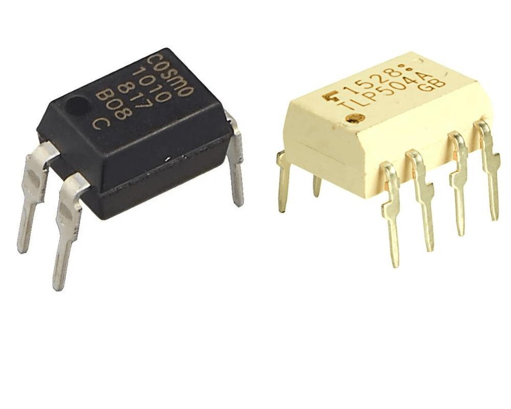
Figure 3: Opto-Coupler and Opto-Isolator Packages
Photocouplers, also known as opto-couplers or opto-isolators, are electronic parts that use light to send electrical signals between two circuits that need to be kept separate. This separation helps prevent high voltages from damaging the circuit that receives the signal. The design and packaging of these parts change depending on whether they are used in low-voltage or high-voltage situations.
Low-Voltage Applications: In low-voltage setups, opto-couplers are usually found in packages that look like standard Dual-In-Line (DIL) Integrated Circuits (ICs) or Small Outline Integrated Circuit (SOIC) packages. These formats are commonly used in Surface Mount Technology (SMT), making them easy to fit into modern, compact electronic designs. The packaging allows the part to be easily included in printed circuit boards (PCBs) while still keeping different sections of a circuit separate.
High-Voltage Applications: For high-voltage situations, opto-isolators are often designed with stronger packaging to handle higher isolation voltages. These packages might be rectangular or cylindrical and are made to provide more protection than standard IC packages. This feature is useful in power systems or other setups where the voltage difference between circuits can be large, requiring extra safety measures.
Photocoupler Terminology and Symbols
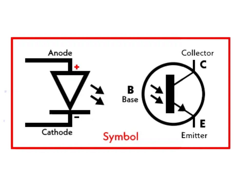
Figure 4: Circuit Diagram Symbol of a Photocoupler
While "opto-coupler" and "opto-isolator" are often used to mean the same thing, there are small differences between them based on how they are used:
Opto-couple usually refers to parts used in systems where the voltage difference between circuits does not go over 5,000 volts. These parts are often used for sending analog or digital signals across separate circuits in different electronic setups.
Opto-isolators are specially made for use in high-power systems where the voltage difference can be more than 5,000 volts. The main job is similar—to send signals while keeping electrical separation—but these parts are made to handle the more demanding electrical setups found in power distribution and industrial systems.
In Circuit Diagrams, the symbol for an opto-coupler typically shows an LED (which acts as the transmitter) on one side and a phototransistor or photodarlington (which acts as the receiver) on the other. This symbol shows how the part works on the inside, showing how light is used to create an electrical link between the separate circuits. The LED gives off light when current flows through it, which is then picked up by the phototransistor, allowing the signal to pass through while keeping the circuits electrically separate.
Key Specifications of Photocouplers
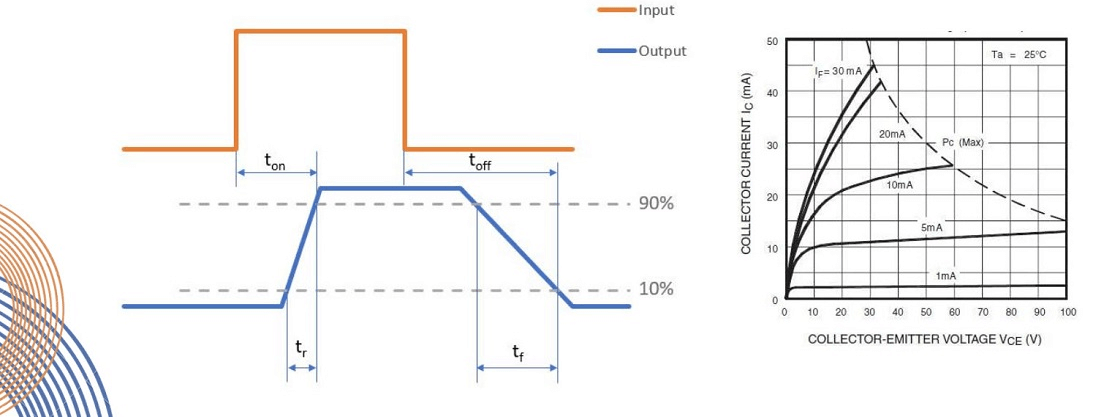
Figure 5: Photocoupler Input-Output Timing and Collector-Emitter Voltage Characteristics
When choosing a photocoupler, it's helpful to understand its key features to make sure it fits your needs.
Current Transfer Ratio (CTR): This is the ratio of output current to input current. In simpler terms, it shows how much current on the input side is transferred to the output side. CTR values can vary widely, from 10% to over 5,000%, depending on the type of photocoupler. A higher CTR means the device is more effective at passing the signal from input to output, which is important for applications where precise signal control is needed.
Bandwidth: This feature tells you the maximum speed at which the photocoupler can handle data. Phototransistor-based photocouplers usually have a bandwidth of around 250 kHz, making them suitable for many common uses. However, if you need something faster, be aware that photodarlington-based photocouplers might be slower due to their design, which affects how quickly they respond.
Input Current: This refers to the amount of current needed to power the LED on the input side of the photocoupler. The input current is an important factor because it affects how much power the device uses and how well it works with the other parts of your circuit.
Output Device Maximum Voltage: For transistor-based photocouplers, this is the highest voltage that the output transistor can handle. It’s important to ensure that this voltage rating is higher than the maximum voltage your application will use, to avoid damaging the device.
Differences Between Photocouplers and Solid-State Relays
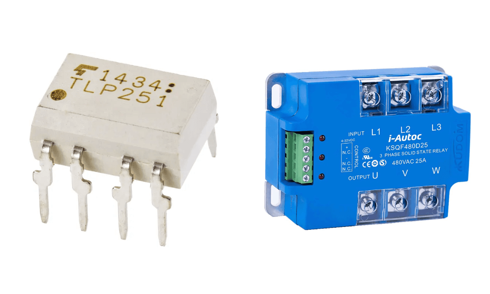
Figure 6: Photocoupler and Solid-State Relay
Photocouplers and solid-state relays (SSRs) both use light to isolate signals, but they are used in different ways based on their design.
Photocouplers are generally used in low-power situations where the main goal is to transmit and isolate signals. They are ideal for protecting sensitive electronic parts from high voltage spikes or noise, making sure the signal is passed cleanly from one part of the circuit to another.
Solid-State Relays (SSRs), on the other hand, are designed to switch higher power levels. Unlike photocouplers, SSRs often have extra parts like surge protection and zero-crossing switching (for AC signals), which helps reduce electrical noise and makes the relay last longer. SSRs are usually larger, and because they handle higher currents, they often need heat sinks to manage heat and screw terminals for secure connections.
Conclusion
Photocouplers help keep circuits safe and working well by letting signals pass through while keeping the circuits separated. They protect low-voltage circuits from high-voltage spikes and reduce electrical noise, which makes them very helpful in many electronic devices. Whether they're used to simply pass signals between circuits or in more complex power systems, choosing the right photocoupler—whether it’s a standard opto-coupler or a stronger opto-isolator—can make a big difference in how well an electronic system works. As technology keeps advancing, these devices will continue to be very helpful, acting as protectors of our electronic devices.
Frequently Asked Questions [FAQ]
1. What is the application of an opto-isolator?
The application of an opto-isolator is to keep different parts of a circuit separate while allowing signals to pass between them. This helps protect sensitive parts of a circuit from high-voltage spikes or electrical noise. Opto-isolators are often used in power supplies, microcontroller interfaces, and industrial control systems to prevent damage to low-voltage components.
2. When should you use an opto-isolator?
You should use an opto-isolator when you need to protect low-voltage parts of a circuit from high-voltage surges or electrical noise. It’s also useful when different parts of your system need to work together without being directly connected. This is helpful when circuits have different ground levels or when they need to stay electrically separate for safety reasons.
3. What is the primary purpose of an optocoupler?
The primary purpose of an optocoupler is to let signals pass between two separate circuits using light, while keeping the circuits electrically apart. This prevents high-voltage circuits from affecting low-voltage circuits, helping to protect delicate parts from being damaged.
4. Why would you use an optocoupler instead of a relay?
You would use an optocoupler instead of a relay when you need faster switching, a longer lifespan, and quieter operation. Unlike relays, optocouplers don’t have moving parts, so they can switch more quickly and last longer. They also take up less space and provide better electrical isolation.
5. What are the disadvantages of optocouplers?
The disadvantages of optocouplers include their limited ability to handle high current and voltage compared to relays. Some optocouplers, especially those with phototransistors, can be slower to respond. They can also wear out over time because the LED inside degrades. Optocouplers might not be the best choice for controlling very high power, where relays or solid-state relays would work better.
About us
ALLELCO LIMITED
Read more
Quick inquiry
Please send an inquiry, we will respond immediately.
Linear Power Supplies
on August 28th
Understanding RF Mixers in Modern Communication Systems
on August 28th
Popular Posts
-

What is GND in the circuit?
on January 1th 3040
-

RJ-45 Connector Guide: RJ-45 Connector Color Codes, Wiring Schemes, R-J45 Applications, RJ-45 Datasheets
on January 1th 2609
-

Fiber Connector Types: SC Vs LC And LC Vs MTP
on January 1th 2162
-

Understanding Power Supply Voltages in Electronics VCC, VDD, VEE, VSS, and GND
on November 13th 2080
-

Comparison Between DB9 and RS232
on January 1th 1790
-

What Is An LR44 Battery?
Electricity, that ubiquitous force, quietly permeates every aspect of our daily lives, from trivial gadgets to life-threatening medical equipment, it plays a silent role. However, truly grasping this energy, especially how to store and efficiently output it, is no easy task. It is against this background that this article will focus on a type of coin cell battery that may seem insignificant on the...on January 1th 1754
-

Understanding the Fundamentals:Inductance Resistance, andCapacitance
In the intricate dance of electrical engineering, a trio of fundamental elements takes center stage: inductance, resistance, and capacitance. Each bears unique traits that dictate the dynamic rhythms of electronic circuits. Here, we embark on a journey to decipher the complexities of these components, to uncover their distinct roles and practical uses within the vast electrical orchestra. Inductan...on January 1th 1706
-

CR2430 Battery Comprehensive Guide: Specifications, Applications and Comparison to CR2032 Batteries
What is CR2430 battery ?Benefits of CR2430 BatteriesNormCR2430 Battery ApplicationsCR2430 EquivalentCR2430 VS CR2032Battery CR2430 SizeWhat to look for when buying the CR2430 and equivalentsData Sheet PDFFrequently Asked Questions Batteries are the heart of small electronic devices. Among the many types available, coin cells play a crucial role, commonly found in calculators, remote controls, and ...on January 1th 1642
-

What Is RF and Why Do We Use It?
Radio Frequency (RF) technology is a key part of modern wireless communication, enabling data transmission over long distances without physical connections. This article delves into the basics of RF, explaining how electromagnetic radiation (EMR) makes RF communication possible. We will explore the principles of EMR, the creation and control of RF signals, and their wide-ranging uses. The article ...on January 1th 1624
-
Comprehensive guide to hFE in transistors
Transistors are crucial components in modern electronic devices, enabling signal amplification and control. This article delves into the knowledge surrounding hFE, including how to select a transistor's hFE value, how to find hFE, and the gain of different types of transistors. Through our exploration of hFE, we gain a deeper understanding of how transistors work and their role in electronic circu...on November 13th 1567


