Understanding RF Mixers in Modern Communication Systems
Frequency mixers are important components in radio frequency (RF) systems, found in devices like radios, cell phones, and satellites. Their main job is to combine two signals to create new ones at different frequencies, known as frequency mixing. Audio mixers and RF mixers serve distinct functions in sound and signal processing. This article explains how RF mixers work, combining signals and using different circuits to create new frequencies by adding and subtracting the originals. It focuses on how components like diodes and transistors behave nonlinearly, changing the amplitude and phase of signals. The article covers various types of mixers, from simple single-diode designs to more advanced triple-balanced ones. It also explains how mixers are used in RF circuit design and signal processing, highlighting their importance in modern technology.Catalog
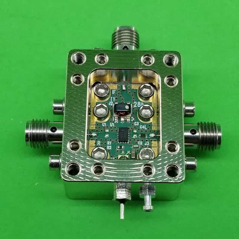
Figure 1: RF Frequency Mixer
The Non-Linear Signal Mixing
The essence of signal mixing comes from the non-linear behavior of certain circuit components like diodes or transistors. Unlike linear components that simply amplify or reduce the strength of signals, non-linear elements cause the input signals to interact in a way that creates entirely new frequencies. This non-linear interaction, often referred to as "mixing," is the mechanism that produces frequencies not present in the original signals.
When two signals are fed into a mixer, they pass through a non-linear device that effectively multiplies these signals together. So, the device combines the signals in a way that new frequencies emerge. Mathematically, this can be represented as multiplying two input voltages:
![]()
Where ![]() and
and ![]() represent the two input signals in the form of sine waves:
represent the two input signals in the form of sine waves:
![]()
![]()
Here, A and B are the amplitudes, while ![]() and
and ![]() are the frequencies of the two signals. The interaction between these sine waves can be further simplified using trigonometric identities. When multiplied, the result breaks down into two components:
are the frequencies of the two signals. The interaction between these sine waves can be further simplified using trigonometric identities. When multiplied, the result breaks down into two components:
![]()
This shows that the output signal now contains two new frequencies: one at the sum f1+f2 and another at the difference f1-f2. These are known as the "sum" and "difference" frequencies, which arise due to the non-linear properties of the mixer.
To make this more concrete, let's consider an example where two signals with frequencies of 1 MHz and 0.75 MHz are fed into a mixer. Following the same principle as above, we can calculate the new frequencies produced.
First, the sum frequency:
![]()
Next, the difference frequency:
![]()
So, after mixing, the output signal will include two new frequencies: 1.75 MHz and 0.25 MHz. These new signals are direct results of the mixing process, showing how a non-linear circuit shifts and spreads the input signal frequencies. This ability to create new frequency components is what makes signal mixing an important tool in RF applications, enabling tasks such as frequency conversion, modulation, and signal processing.
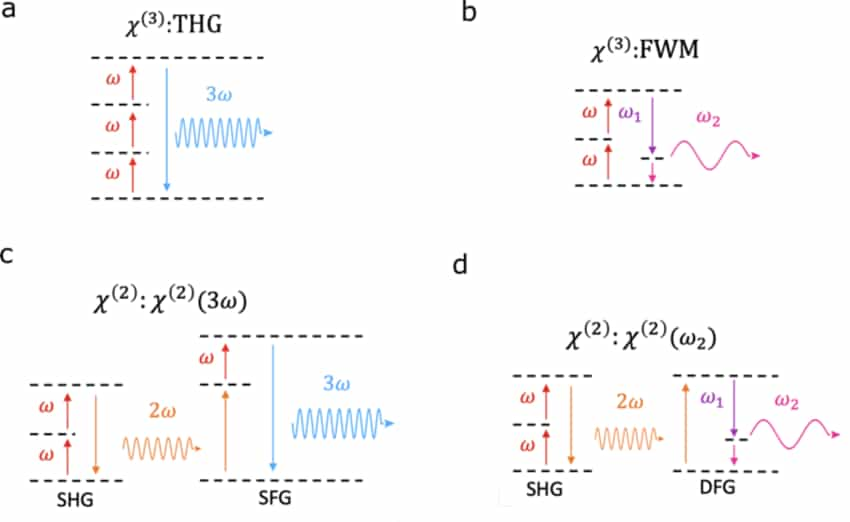
Figure 2: Nonlinear Frequency Mixing Processes
How RF Mixing and Multiplication Works
RF mixing, also referred to as multiplication, is a process in radio frequency (RF) technology that involves combining two signals to generate new frequencies, the sum and difference of the original signal frequencies.
Let's consider two sine waves, ![]() and
and ![]() , where:
, where:
![]()
![]()
When these two signals are input into a non-linear element (like a diode or transistor), the result is not a simple sum of the signals, but a product. Non-linear components alter the input signals, producing multiple output frequencies. These elements do not follow the superposition principle, meaning the output is no longer directly proportional to the inputs.
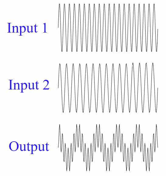
Figure 3: Mixing or Multiplying Two Signals Together
For example, a diode has a non-linear voltage-current relationship that is good for the mixing process. This relationship can be modeled by an exponential function that is sometimes approximated by a polynomial series in practical applications. Similarly, transistors and FETs can be set to operate in a non-linear region to achieve the same mixing effect.
The multiplication of A(t) and B(t) in a non-linear element can be mathematically described as follows:
![]()
Simplified: ![]()
This equation shows that the output, ![]() , contains two new frequencies: one at the sum of the input frequencies
, contains two new frequencies: one at the sum of the input frequencies ![]() and one at the difference
and one at the difference ![]() . These sum and difference frequencies are the outcomes of the mixing process.
. These sum and difference frequencies are the outcomes of the mixing process.
If you looked at this output waveform, it would seem much more complicated than the original sine waves. The size and speed of the new waveform change because of the mixing, creating a signal with many different frequencies. In addition to the sum and difference frequencies, other higher-level harmonics can also show up, depending on how non-linear the system is and how strong the input signals are.
Fourier analysis or a time-based simulation can help show this complexity. These tools break down the waveform to show how simple sine waves turn into a signal with many frequencies. These visuals help explain how non-linear parts change RF signals and why this process matters in RF engineering.
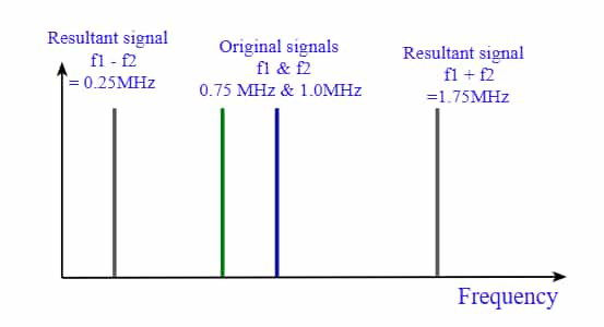
Figure 4: Mixing Two RF Signals
RF Mixer Circuit Symbol
In RF circuit design, the RF mixer symbol is more than just a simple marker on a schematic. This symbol, a circle intersected by an "X," represents the point where two signals combine and interact in the system. It visually guides engineers by pinpointing the location where frequency conversion takes place. The symbol is labeled with three important ports: RF (radio frequency), LO (local oscillator), and IF (intermediate frequency). These labels aren’t just for formality, they provide information about how signals move through the circuit, helping anyone reading the diagram to quickly and accurately grasp how the system functions. Proper labeling ensures clear communication of the design’s purpose, making it easier for engineers to analyze and implement the schematic.
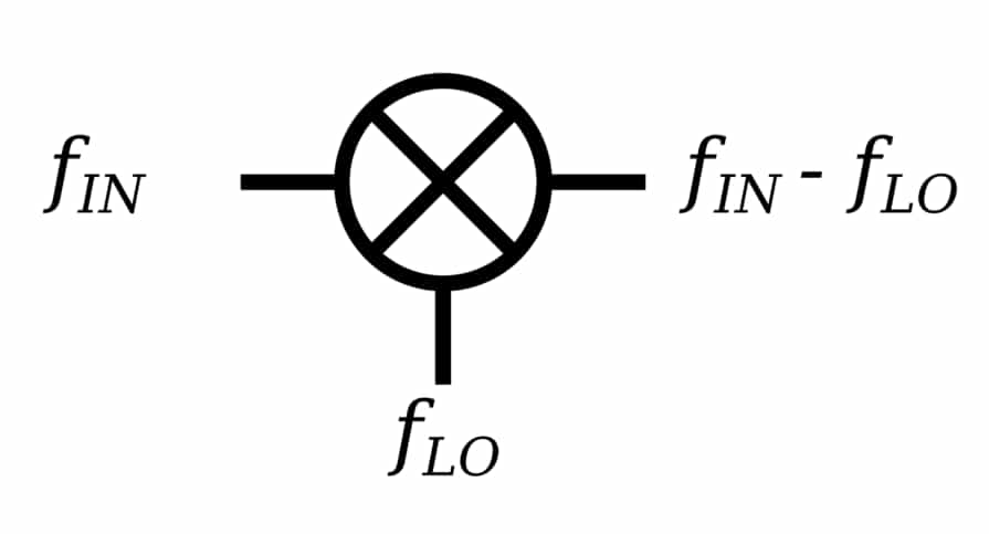
Figure 5: RF Mixer Circuit Symbol
RF Mixer Circuits
A single diode mixer is one of the simplest designs, using just a single diode to perform frequency mixing. This minimalistic approach makes it an appealing option for projects with tight budgets or space limitations. Its compact size and low cost are attractive features, but this simplicity introduces challenges. Single diode mixers struggle with isolating input signals from each other and from the output that often leads to signal distortion. As a result, they may not be the best choice for applications that require clean, precise signal processing.
More advanced mixers use extra parts like multiple diodes, transistors, or integrated circuits. These improve performance by reducing interference and keeping the signal clear. While they work better, they also cost more and are more complicated. Deciding on a higher-end mixer means weighing the better performance against the extra cost and complexity.
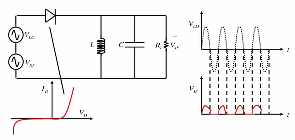
Figure 6: A Single Diode Mixer
Types of RF Mixers
Passive Mixers
Passive mixers rely on simple components, such as diodes, without using any active elements that amplify signals. Even though these mixers don’t increase signal strength, they can still perform well under certain conditions. Schottky diodes are commonly used in passive mixers because they have a low turn-on voltage, making them efficient for switching signals. However, these mixers require additional components like baluns (a type of RF transformer) to balance the circuit. This balance is important, especially for designs like balanced or double-balanced mixers. However, using a balun can reduce the mixer's frequency range, limiting its flexibility in some cases.
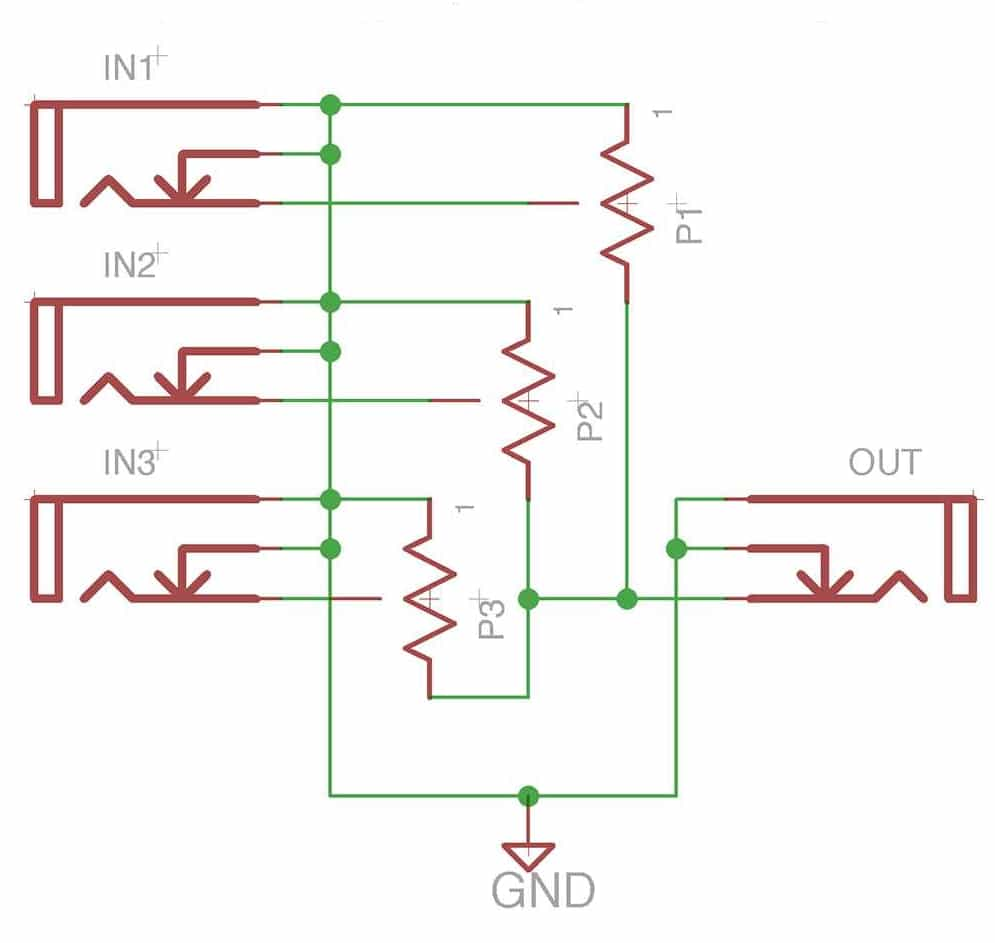
Figure 7: A Passive Mixer
Active Mixers
Active mixers incorporate amplifying elements such as bipolar transistors, FETs (field-effect transistors), or even vacuum tubes. These elements not only allow the mixer to combine frequencies but also to boost signal strength. This amplification is useful in more complex RF systems, where maintaining strong signal levels is required for overall performance.
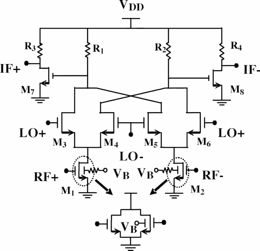
Figure 8: Active Mixer
Unbalanced Mixers
Unbalanced mixers combine two input signals in a straightforward way, resulting in an output that contains both the sum and the difference of the original input frequencies, along with some remnants of those original signals. While they are simple and can be cost-effective, unbalanced mixers tend to introduce a lot of noise and interference. This makes them less suitable for applications where clean, high-quality signals are required.
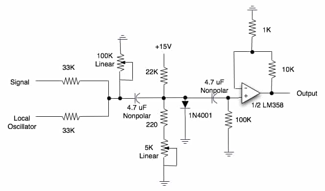
Figure 9: Unbalanced Mixer
Single-Balanced Mixers
Single-balanced mixers offer an improvement over unbalanced designs by using a balun or similar balancing circuitry to filter out unwanted signal components. This type of mixer uses two diodes and a 180-degree hybrid to achieve better separation between the local oscillator and the RF input signal. By doing so, it reduces issues like intermodulation distortion and minimizes leakage from the local oscillator, resulting in cleaner output signals.
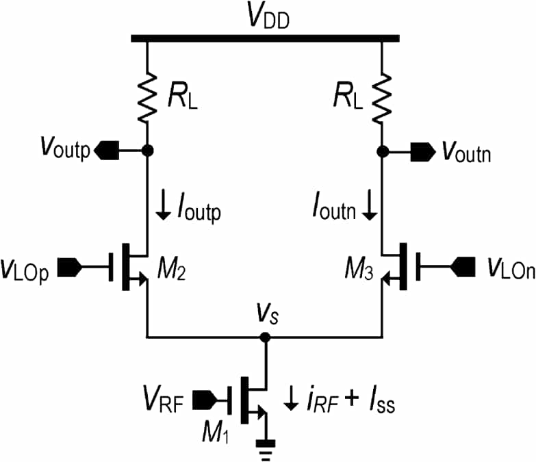
Figure 10: Single-Balanced Mixer
Double-Balanced Mixers
Double-balanced mixers improve on the balancing approach by using four Schottky diodes in a ring and adding baluns to the RF and local oscillator inputs. This design offers much better isolation between the input signals and the intermediate frequency output, reducing unwanted signals by up to 75% compared to simpler designs. Though slightly more complex and costly, it's the preferred choice for high-performance RF systems because of its reliability and better performance.
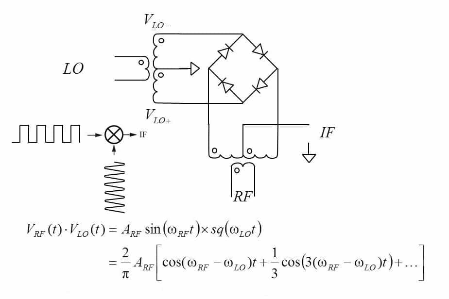
Figure 11: Double-Balanced Mixer
Triple-Balanced Mixers
The triple-balanced mixer, often called a doubly double-balanced mixer, represents the peak of mixer design. It combines two double-balanced mixers, using double the number of diodes and junctions. This design provides exceptional isolation and greatly suppresses spurious signals and intermodulation distortion. However, this improved performance comes at a price, it requires a higher local oscillator drive and involves more components, making it more complex and expensive than simpler mixers.
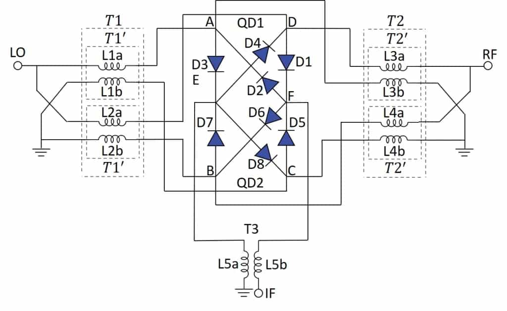
Figure 12: Triple-Balanced Mixer
Types of RF Mixing Methods
Nonlinear Mixing
In this method, the natural nonlinear behavior of electronic components like diodes or transistors is used to mix signals. When RF signals pass through these devices, they create new frequencies, including the sum and difference of the original signals, along with some unwanted extra frequencies.
This method is simple and can produce a variety of frequencies, but the downside is that it also creates unwanted signals that can interfere with performance. Engineers solve this by designing circuits to reduce these extra signals or by using filters to clean up the output. Nonlinear mixing is often used when a less complex design is required but good performance is still important.
Switching or Sampling
Switching or sampling is a more accurate way to mix RF signals compared to nonlinear methods. It involves turning components like transistors or FETs on and off quickly, in sync with a local signal. This process effectively samples the input signal and creates the desired output frequencies with better accuracy.
The main advantage is that it reduces unwanted signals, resulting in a cleaner output. This makes it a great choice for systems that need high-quality signals like advanced communication technologies. The precise control of the switching process allows for better frequency translation, making the signal processing more efficient.
Types of Mixer Ports and Frequency Conversion in RF Systems
Here's a main types of mixer ports and how they work:
RF Port (Radio Frequency Port): This port receives the incoming signal, usually from communication or radar systems that needs its frequency changed. It usually handles high-frequency signals.
LO Port (Local Oscillator Port): The LO port gets a steady, strong signal with a known frequency. This signal is used as a reference to combine with the RF signal, keeping the mixing process stable and predictable.
IF Port (Intermediate Frequency Port): After the RF and LO signals are combined, the resulting signal goes to the IF port. This new signal, either the sum or difference of the RF and LO frequencies, is ready for further processing.
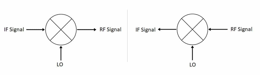
Figure 13: Mixer Ports
Frequency Conversion Processes
Down-Conversion: This process lowers the frequency of the incoming RF signal, making it easier to process. It's mainly used in receivers. The IF port outputs a signal that is usually the difference between the RF and LO frequencies.
Up-Conversion: This process increases the signal's frequency for transmission. Higher frequencies are better for sending signals over long distances. The LO signal controls the timing, ensuring the mixer works correctly and outputs a clean high-frequency signal for transmission.
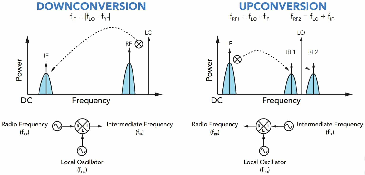
Figure 14: Frequency Conversion Processes
Applications of RF Mixers
• Superheterodyne Receivers
In superheterodyne receivers, RF mixers change incoming high-frequency signals into intermediate frequencies (IF) that are easier to work with. This is good for radios, TVs, and satellite receivers. By converting signals to an intermediate frequency, the system can better separate useful signals from noise or unwanted signals. This improves both the selectivity (the ability to focus on specific frequencies) and sensitivity (the ability to detect weak signals) of the receiver.
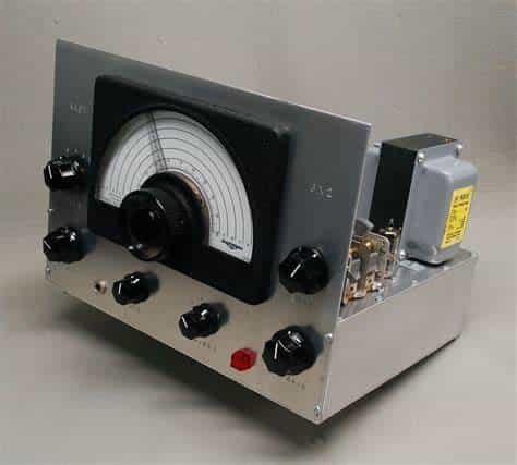
Figure 15: Superheterodyne Receiver
• Frequency Translation
A major function of an RF mixer is to shift signal frequencies, either up or down, depending on the need. In receivers, it lowers high-frequency signals to a lower range. In transmitters, it raises low-frequency signals like those from baseband or intermediate frequencies to higher radio frequencies for transmission. Whether in cell phones, broadcasting, or data systems, frequency translation helps ensure signals are at the right frequency for their purpose.
• Radar Systems
RF mixers are useful in radar systems because they adjust returned signals to frequencies that are easier to analyze. When a radar sends a signal, the returned signal’s frequency changes based on how far away and how fast the target is moving. Mixers help bring these signals to a usable frequency range, allowing for accurate speed and position calculations, ideal for air traffic control, ship navigation, and weather monitoring.
• Satellite Communications
In satellite communications, RF mixers help transmit and receive signals at the best frequencies. During uplink (sending signals to the satellite), they convert signals to frequencies that can pass through the atmosphere easily. During downlink (receiving signals from the satellite), they convert the signals back into a form that ground stations can process. This frequency management is suitable for reliable communication, whether for weather forecasts, TV broadcasts, or GPS.
• Phase Detection and Measurement
RF mixers are also used for phase detection to track the difference in phase between two signals. This is useful in Phase-Locked Loops (PLLs), that keep one signal’s frequency locked to a reference frequency. By comparing the phase of the input and output signals, the system can adjust the output to stay in sync with the reference, which ensures stable signals, especially in systems needing precise frequency control, like frequency synthesis, modulation, and demodulation.
• Frequency Modulation and Demodulation
RF mixers are good in systems that use Frequency Modulation (FM) to send information. When modulating, they shift the signal to the frequency for transmission. When demodulating, they convert the received signal back to its original form so the information (like voice or music) can be understood. This two-step process is good for clear communication in radios, TV, and other broadcasting systems.
• Signal Conditioning and Processing
In advanced fields like electronic warfare and signal analysis, RF mixers help refine and process incoming signals. The system can make it easier to extract patterns or information by mixing signals with reference frequencies. This process is ideal for spotting threats, decoding messages, and analyzing signals. RF mixers help to improve both defense and signal analysis.
Conclusion
The study of RF mixers looks closely at how they work, their different types, and their uses, showing how important they are in modern RF technology. From the basic idea of mixing signals to the more advanced designs of triple-balanced mixers. Different types of mixers are designed for specific needs, showing how adaptable and precise RF engineering needs to be. Whether it's in superheterodyne receivers or satellite communications, RF mixers are good for handling and converting frequencies. The article also points out design factors, like port configuration and mixer circuit symbols that help these devices work well in RF systems. With ongoing improvements in RF technology, mixer designs keep getting better, improving signal quality and system performance.
Frequently Asked Questions [FAQ]
1. What is the difference between RF mixer and modulator?
An RF mixer combines two input signals, a radio frequency signal and a local oscillator signal, to produce new frequencies through a process called frequency mixing. This process generates both sum and difference frequencies of the original inputs, for frequency conversion in radio receivers and transmitters. On the other hand, a modulator manipulates a carrier signal to encode information from a data signal. This modulation can involve altering the amplitude, frequency, or phase of the carrier signal to represent the data, facilitating its transmission over a medium.
2. What are examples of RF mixer devices?
Double-Balanced Mixers: These devices offer good isolation between the ports and are used in both upconversion and downconversion applications in communications and radar systems.
Single-Balanced Mixers: These mixers provide a compromise between performance and cost, used in applications where moderate isolation is sufficient.
Triple-Balanced Mixers: Employed in high-performance applications, these mixers offer excellent port isolation and intermodulation performance, ideal for complex signal environments.
3. How to detect radio frequency?
Detecting radio frequencies involves the use of a device called a spectrum analyzer. This tool scans through a range of frequencies and identifies the presence of RF signals, displaying their strength and characteristics. Another common method involves using RF detectors, which convert high-frequency signals into measurable DC outputs that indicate the presence and strength of RF signals.
4. What is the main advantage of RF?
The main advantage of RF (radio frequency) technology is its ability to transmit data over long distances without physical connections. RF communication can penetrate various materials and traverse wide geographic areas, making it best for mobile communications, broadcasting, and remote control systems. RF technology supports a wide range of frequencies, allowing for multiple communications channels and applications.
5. Is Wi-Fi an RF signal?
Yes, Wi-Fi operates using RF signals. Wi-Fi technology transmits data using radio frequencies in the 2.4 GHz and 5 GHz bands. These frequencies allow for the wireless transmission of data between devices, such as between a wireless router and a computer, using electromagnetic waves. This enables devices to connect to the internet and communicate with each other without the need for wired connections.