NE555 introduction, internal structure, operating mode, applications
The NE555 is a monolithic integrated circuit timer capable of producing various types of timing signals. It is extensively used in electronic clocks, power management, calculators, LED displays, and other electronic devices across various fields. This article aims to provide detailed information about the NE555, including its background, design, internal structure, pin descriptions, operational modes and principles, and applications, to help you better utilize this chip.Catalog
Introduction to the NE555
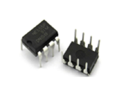
The NE555 is one of the models in the 555 timer IC series. The pin functions and applications of this series are mutually compatible, but different chip models might vary in terms of price, stability, power-saving performance, and oscillation frequency.
The 555 timer IC is a ubiquitous multifunctional component in timing circuits, requiring only a minimal number of resistors and capacitors to generate the various pulse signals essential for digital electronic products. The primary use of the NE555 lies in its ability to form a time-base circuit with an internal timer, thereby providing precise timing pulses for other circuits.
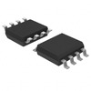
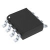
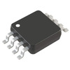
It has two main packaging types: the DIP (Dual In-line Package) with an 8-pin configuration that can be directly inserted, and the more compact SOP-8 package, suitable for space-sensitive applications.
Alternatives and equivalent options:
• BL5372
• NA555
• KR3225Y
Design of the NE555 Timer
The 555 timer IC was designed by Hans R. Camenzind in 1971 for Signetics (later acquired by Philips), featuring 25 transistors, 2 diodes, and 15 resistors, all accessible through an 8-pin DIP-8 package. This foundational design spawned various derivatives, including the 556 (with two 555 timers in a DIP-14 package) as well as models 558 and 559.
The NE555 operates within a temperature range of 0°C to 70°C, serving the general market, while its military-grade counterpart, the SE555, is designed to withstand extreme temperatures from -55°C to 125°C. The packaging options for the 555 timer IC reflect its versatility and application range, offering high-reliability metal (indicated by the suffix T) and low-cost epoxy resin (V) casings, thus the comprehensive labels NE555V, NE555T, SE555V, and SE555T. The naming convention of "555" is commonly believed to originate from its internal 5KΩ resistors, although Camenzind himself refuted this, clarifying that the selection of the "555" name was arbitrary.
In the pursuit of energy efficiency, the 555 series includes low-power models like the 7555 and the CMOS-based TLC555, which boast lower energy consumption compared to the standard models. As claimed by the manufacturers, the 7555 model does not require a bypass capacitor between the control pin and ground nor a decoupling capacitor between the power supply and ground to eliminate noise, aiming for a design advancement that reduces complexity and enhances performance.
Internal Composition of the NE555
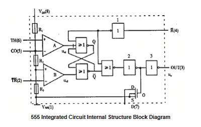
The NE555 is a classic integrated circuit. Its internal circuit structure consists of three key operational units: a voltage comparator with an output stage, various comparators, and an RS flip-flop. Below is a detailed analysis of the NE555's internal circuit:
Voltage Comparator: The NE555 includes a voltage comparator internally, used for checking the supply voltage and seamlessly linking its output to the RS flip-flop to ensure accurate voltage monitoring.
Output Stage: Connected to the RS flip-flop, the output stage primarily manages the state of the output pin (pin 3). The NE555's output architecture is an open-drain design, incapable of independently transmitting high-level signals and requiring an external pull-up resistor to bring the output pin to a high state when a high-level signal is needed.
Comparators: In the NE555, two comparators stand out: the threshold comparator and the trigger comparator, associated with pins 6 (THR) and 2 (TRIG), respectively.
As the voltage on the threshold pin (pin 6) increases, the threshold comparator elevates its output to a high-level signal. If the threshold voltage exceeds the trigger voltage, the comparator's output changes accordingly.
When the voltage on the trigger pin (pin 2) decreases, the trigger comparator reduces its output to a low-level signal. Output changes occur when the trigger voltage drops below the threshold voltage.
RS Flip-Flop: The NE555 includes an RS flip-flop internally, used to store the state of the output pin (pin 3). The inputs of the RS flip-flop are controlled by the outputs of the threshold comparator and the trigger comparator.
The R input comes from the threshold comparator's output, overseeing the RS flip-flop's reset mechanism.
The S input comes from the output of the trigger comparator, managing the setup of the RS flip-flop.
The analysis overview of the NE555's internal circuit highlights its complex design, enabling it to reliably perform its role as a versatile timing solution.
Operational Modes of the NE555
The NE555 timer is a versatile component in electronic design, operating in three main modes, each tailored to specific circuit functions:
Astable Mode: This configuration is characterized by its inherent instability, oscillating indefinitely without entering a stable state. It is widely used in applications requiring repetitive signals, such as flashers, audio generators, pulse generators, and timing circuits, to facilitate continuous output oscillation.
Bistable Mode: Reflecting the stability of a bicycle kickstand, whether raised or lowered, this mode maintains stability in two different states, only transitioning with external intervention. Known as bistable due to its two stable conditions, it allows the NE555 to act as a toggle switch, responding to external inputs to change its state.
Monostable Mode: Similar to a door equipped with a closer, it remains securely closed until forcibly opened. In this mode, the NE555 stabilizes in a single state, activated only by an external trigger and automatically returning to its original state after the trigger is removed. This monostable operation is suitable for applications requiring a single timing output signal, such as timers, touch switches, and capacitance meters.
Operating Principle of the NE555
When the power supply voltage Vcc is initiated, the circuit begins to operate, prompting the capacitor C to start charging immediately. Once the voltage across capacitor C reaches two-thirds of Vcc, the internal comparator's output turns high, switching the OUT output from low to high. Subsequently, a decrease in capacitor voltage to one-third of Vcc triggers the internal comparator to revert its output to low, causing the OUT output to switch back from high to low. Thereafter, capacitor C resumes charging, propelling the circuit into a new operating cycle.
The period time T (in seconds) is determined by the values of the external capacitor C and two external resistors R1 and R2, with the formula: T = 0.693 × (R1 + 2 × R2) × C. The duty cycle D, representing the proportion of the square wave's high-level duration over the entire cycle, is calculated as: D=(R1+R2)/(R1+2×R2). Therefore, by fine-tuning the values of capacitor C and resistors R1 and R2, the period and duty cycle of the square wave waveform can be modified.
Fundamentally, the operating principle of the NE555 revolves around the construction of a timing circuit. By adjusting the values of external capacitors and resistors, the period and duty cycle can be controlled, facilitating the generation of the desired pulse waveforms.
Applications of the NE555
NE555 Infrared Control Delay Light:
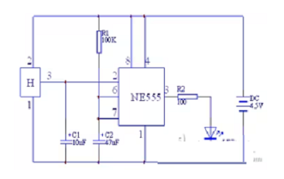
Modern households are commonly equipped with infrared remote controls, and we can use these existing remotes to control infrared remote-controlled delay lights. In this setup, "H" represents the integrated infrared receiver, and "C1" acts as a filtering capacitor. The signal from the remote control, after being filtered by C1, generates a negative pulse, triggering the monostable circuit of the NE555 to activate.
NE555 Boiling Water Alarm:
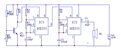
This alarm system ingeniously designs a temperature control circuit, a low-frequency oscillator, and a high-frequency oscillator. Temperature control is achieved by combining RP, RT, and VT1. The low-frequency oscillation involves IC1, R2, R3, and C1, where VT1 affects its reset pin (pin 4). Simultaneously, the high-frequency oscillator composed of IC1, R4, R5, and C2 is modulated by IC1. When the preset temperature is reached, RT's resistance decreases, causing VT1 to cease functioning. Consequently, IC1 oscillates, emitting low-frequency pulses that modulate the high-frequency oscillator in IC2, thereby producing a sound alarm.
NE555 Touch-Activated Timing Switch:
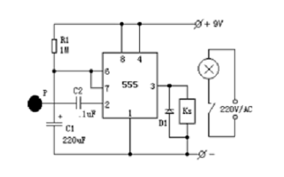
The configuration above is a monostable circuit, where IC1 (NE555 timer) under normal conditions sees capacitor C1 fully discharged through NE555's pin 7, resulting in a low output at pin 3, keeping the relay (KS) and connected lamp off. A simple touch on the metal plate "P" can activate the lamp, utilizing the stray signal voltage from the human body transmitted to the NE555 trigger pin through C2, flipping the output to high. This operation activates the relay (KS) and lights up. At the same time, the timer starts as R1 charges C1, with the timing duration set by T1=1.1R1*C1, roughly equivalent to four minutes, based on the provided component values. The diode options for D1 include models 1N4148 or 1N4001.
Five Classic Circuits of the NE555
Basic NE555 Timer Circuit
This basic yet widely used circuit, consisting of the NE555 chip along with resistors and capacitors, conveniently generates millisecond-level timing signals, such as pulses and square waves. Its hallmark lies in its simplicity and precision, easily creating accurate timing signals.
NE555 Monostable Circuit
Capable of generating a single pulse signal, this configuration is built around the NE555 along with various resistors and capacitors. By altering these components, pulse width and delay time can be adjusted, making it an ideal choice for creating trigger and synchronization signals. The circuit is characterized by its ability to produce a single pulse signal, with adjustable pulse width and delay time.
NE555 Bistable Circuit
This circuit implements a logic flip-flop function, allowing the modification of trigger timing and threshold voltage through the adjustment of resistors and capacitors, commonly used for logic flip-flops and voltage comparison applications.
NE555 Square Wave Generator Circuit
Designed to produce square wave signals, adjusting the resistors and capacitors within this circuit changes its frequency and duty cycle. Mainly used for generating digital and modulation signals, its ability to customize square wave frequency and duty cycle makes it suitable for numerous digital and modulation tasks.
NE555 Astable Multivibrator Circuit
Composed of two NE555 chips and additional resistors and capacitors, this circuit generates adjustable rectangular wave signals. The frequency and duty cycle can be fine-tuned, making it suitable for producing audio or modulation signals. The circuit is characterized by its ability to provide rectangular waves with customizable frequency and duty cycle.
Frequently Asked Questions [FAQ]
1. What is the function of the NE555?
The SE 555 timer IC operates within a temperature range of -55°C to 125°C, while the IC NE 555 is used within a temperature range of 0°C to 70°C. It has a wide range of applications in the electronics field, such as timers, delays, pulse generation, oscillators, etc.
2. Are the NE555 and IC 555 the same?
Yes, the NE555 timer IC and the 555 timer IC are the same. NE555 is the part number for the timer IC. Generally, the NE555 IC is referred to as the 555 timer IC.
3. What is the operating principle of the NE555?
By connecting the reset input signal to the RESET pin and the set input signal to the TR pin, the 555 timer can act as a low-level effective SR latch (although without an inverse Q output). Therefore, momentarily pulling Set low can act as a "set" and switch the output to a high state (VCC).
About us
ALLELCO LIMITED
Read more
Quick inquiry
Please send an inquiry, we will respond immediately.
What Is a Varistor
on April 7th
A Comprehensive Guide to DIP Packaging - History, Types, Characteristics, References
on March 28th
Popular Posts
-

What is GND in the circuit?
on January 1th 3259
-

RJ-45 Connector Guide: RJ-45 Connector Color Codes, Wiring Schemes, R-J45 Applications, RJ-45 Datasheets
on January 1th 2810
-

Understanding Power Supply Voltages in Electronics VCC, VDD, VEE, VSS, and GND
on November 20th 2624
-

Fiber Connector Types: SC Vs LC And LC Vs MTP
on January 1th 2253
-

Comparison Between DB9 and RS232
on January 1th 1869
-

What Is An LR44 Battery?
Electricity, that ubiquitous force, quietly permeates every aspect of our daily lives, from trivial gadgets to life-threatening medical equipment, it plays a silent role. However, truly grasping this energy, especially how to store and efficiently output it, is no easy task. It is against this background that this article will focus on a type of coin cell battery that may seem insignificant on the...on January 1th 1838
-

Understanding the Fundamentals:Inductance Resistance, andCapacitance
In the intricate dance of electrical engineering, a trio of fundamental elements takes center stage: inductance, resistance, and capacitance. Each bears unique traits that dictate the dynamic rhythms of electronic circuits. Here, we embark on a journey to decipher the complexities of these components, to uncover their distinct roles and practical uses within the vast electrical orchestra. Inductan...on January 1th 1791
-

What Is RF and Why Do We Use It?
Radio Frequency (RF) technology is a key part of modern wireless communication, enabling data transmission over long distances without physical connections. This article delves into the basics of RF, explaining how electromagnetic radiation (EMR) makes RF communication possible. We will explore the principles of EMR, the creation and control of RF signals, and their wide-ranging uses. The article ...on January 1th 1785
-

CR2430 Battery Comprehensive Guide: Specifications, Applications and Comparison to CR2032 Batteries
What is CR2430 battery ?Benefits of CR2430 BatteriesNormCR2430 Battery ApplicationsCR2430 EquivalentCR2430 VS CR2032Battery CR2430 SizeWhat to look for when buying the CR2430 and equivalentsData Sheet PDFFrequently Asked Questions Batteries are the heart of small electronic devices. Among the many types available, coin cells play a crucial role, commonly found in calculators, remote controls, and ...on January 1th 1781
-
Comprehensive guide to hFE in transistors
Transistors are crucial components in modern electronic devices, enabling signal amplification and control. This article delves into the knowledge surrounding hFE, including how to select a transistor's hFE value, how to find hFE, and the gain of different types of transistors. Through our exploration of hFE, we gain a deeper understanding of how transistors work and their role in electronic circu...on November 20th 1769
