What Is a Varistor
When delving into the protection mechanisms of electronic devices, the importance of varistors simply cannot be overstated. These semiconductor devices might appear straightforward, yet they bear the crucial task of ensuring circuit stability. Varistors, also known as Voltage-Dependent Resistors (VDRs), utilize their unique nonlinear voltage and current characteristics to swiftly intervene when voltage spikes occur, thereby guaranteeing the smooth operation of circuits. They instantly "wake up" in response to overvoltage threats from external disturbances. By altering their resistance, they skillfully "clamp" inappropriate voltages, thus providing a fortress for the circuit's delicate components against potential hazards. This defense mechanism is both fast and efficient, protecting electronic devices from the impact of sudden voltage fluctuations. This article aims to guide readers through the basic characteristics, operating principles, applications, and advantages and disadvantages of varistors, enriching everyone's fundamental understanding of this crucial field.
Catalog
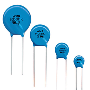
Figure 1: Varistor
Basic Concepts of Varistor
In the intricate world of electronic circuits, the varistor emerges as an indispensable safeguard, akin to a meticulously calibrated safety valve nestled within the complex workings of a clock mechanism. Known in technical parlance as a VDR (Voltage Dependent Resistor), this nuanced semiconductor marvel adapts its resistance in a dance with voltage fluctuations, showcasing a distinctive non-linear prowess. Upon encountering voltage that breaches a specific, preordained threshold, the VDR acts with sudden decisiveness, its resistance plummeting to thwart the assault of dangerous voltage spikes, thus shielding the circuit's more vulnerable components from the specter of damage.
Crafted primarily from zinc oxide (ZnO), a substance in the elite II-VI semiconductor group, embedding a varistor in an electronic circuit bestows upon it a form of rapid-response armor. It's as though the circuit has been fitted with a bulletproof vest, primed to react instantaneously to voltage excesses by diminishing its resistance. This action effectively reins in any potential voltage escalation, ensuring the circuit's integrity remains uncompromised. Among the many characteristics of a varistor, its symbol is particularly prominent - two arrows pointing in opposite directions. More than just a symbol, this embodies the varistor’s bidirectional functionality and ability to handle positive and negative voltage surges, proving its integral role in the electronics world.
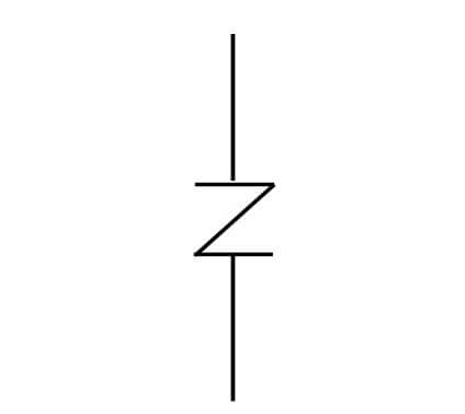
Figure 2: Varistor Circuit Symbol
Type Selection of Varistor
Varistors come in primarily two flavors: the metal oxide varistor (MOV) and the silicon carbide varistor (SiC), each brandishing its own set of unique characteristics tailored for specific scenarios. Imagine being in the market for the most adept bodyguard to shield a circuit; it's not just about hiring muscle but evaluating the "skillset" and "specialization" with a fine-tooth comb.
Metal Oxide Varistors: The Agile Protectors
MOVs have etched their presence solidly in the realm of circuit safeguarding for both home gadgets and industrial machinery, thanks to their unparalleled prowess in soaking up energy spikes and reacting with lightning speed. The crux of a MOV's utility lies in its extraordinary capability to neutralize transient voltages, a trait derived from its zinc oxide-based semiconductor constitution. These materials maintain a stoic resistance under everyday voltage conditions but morph into a highly conductive state under the duress of voltage surges, effectively "clamping down" on unwanted spikes. Envision fitting a circuit with an airbag that not only cushions against sudden impacts but also recoils post-collision, priming the circuit for its regular operations. The selection of a MOV, hence, transcends its rapid response and absorption capacity; it demands a harmonization with the circuit's operational norms and the anticipated voltage aberrations, ensuring swift and staunch defense against abrupt electrical onslaughts.
Silicon Carbide Varistors: The Stalwart Shields in High-Voltage Arenas
In the arena of high-voltage fortifications, SiC varistors stand out for their resilience against the rigors of extreme temperatures and pressures. Their chemical steadfastness and tolerance for scorching conditions render them ideal for the high-stakes environments of power transmission and industrial automation. The inherent robustness of SiC materials underpins their performance amidst electrical storms, positioning them as the go-to shield in scenarios where voltage and environmental extremities are given. Despite SiC's price tag overshooting that of MOVs, their long-haul dependability and adeptness in high-voltage theatrics spell out a cost-effectiveness that's hard to overlook.
When the time comes to pick a varistor, not only consider whether MOV or SiC is more suitable, but also take into account the following conditions: operational voltages, transient dynamics, and battlefield conditions. Should a device face the crucible of high temperatures, SiCs might come to the fore. Yet, the milieu in which the device operates—be it drenched in moisture or choked by corrosive gases—also steers the verdict. The circuit designer is also responsible for ensuring that the chosen protector can handle the current without bending under stress, maintaining the protection of the circuit even when pushed to its limits. Beyond MOVs and SiCs, the surge suppression arsenal is vast, featuring selenium batteries, Zener diodes, and gas discharge tubes, each championing its domain. Zener diodes, for instance, excel in clamping voltages within low-voltage realms, whereas gas discharge tubes take the crown in high-voltage surge arenas. This plethora of options equip circuit designers with the precision to draft a protection strategy ensuring the circuit's integrity across diverse conditions and challenges.
Metal Oxide Varistor
Metal Oxide Varistors (MOVs), recognized for their unparalleled nonlinear voltage protection capabilities, have secured their position as an indispensable element in the realm of electronic circuit design. At the heart of these devices lies a composite of zinc oxide particles, subtly intertwined with a smattering of other metal oxides to craft a complex miniature diode network. In the face of standard operating voltages, this intricate network stands its ground, exhibiting formidable resistance and permitting only a minuscule current to trickle through. Yet, upon encountering transient voltages that soar beyond the norm, the network undergoes a rapid metamorphosis into a state of minimal resistance. It then channels current to neutralize and disperse the surplus energy, thus shielding the circuitry's other constituents from harm.
The process of integrating MOVs into a circuit mandates a meticulous assessment of the circuit's protective requirements. Designers embark on this task by gauging the normal operational voltage of the power lines, aiming to pinpoint an MOV whose threshold voltage marginally surpasses this figure. The journey continues with an examination of the transient voltages' amplitude and frequency, a step crucial for selecting a MOV capable of enduring such fluctuations unscathed. The power source's impedance also plays a pivotal role, influencing both the transient voltage's effect on the circuit and the MOV's proficiency in energy absorption.
Technicians are tasked with strategically embedding MOVs within the circuit board, favoring locales adjacent to power entries or delicate components to guarantee swift intervention when transient episodes strike. A steadfast physical linkage to the circuit is paramount, thwarting any potential for loosening that might arise from vibration or thermal dilation and thus bolstering the circuit's durability over the long haul.
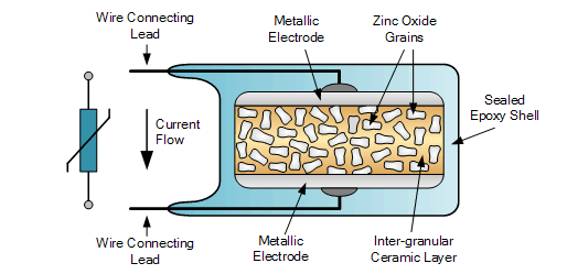
Figure 3: MOV Internal Diagram
Silicon Carbide Varistor
In the arena of voltage protection, Silicon Carbide Varistors shine, especially in settings plagued by high voltages, such as transmission lines and substations. Their dominance stems from their extraordinary material virtues, enabling a superior nonlinear voltage-current reaction under the duress of high-voltage stress, a feat unmatched by their metal oxide counterparts. The chemical robustness and heightened thermal conductivity of silicon carbide furnish these varistors with a performance that remains steadfast under the most daunting of conditions, whether it be towering voltage levels or extreme temperatures.
The adoption and deployment of Silicon Carbide Varistors in high-voltage environments demand a thorough and deliberate approach. Technicians face the challenge of accurately appraising the system's peak voltage capacity, incorporating both the standard operational and the hypothetical transient voltages, to select a varistor with a fitting voltage rating that promises circuit protection across all scenarios. In high-voltage systems, these varistors are often placed at critical points, such as power inputs or near valuable equipment, to provide effective protection quickly during voltage surges.
Beyond high-voltage applications, Silicon Carbide Varistors are increasingly used in devices requiring high reliability and longevity, such as high-speed railways, wind turbines, and solar power systems. In these applications, they not only protect circuits from transient voltages but also ensure stable operation under harsh environmental and electrical conditions.
Figure 4: SIC Internal Diagram
Main Parameters of Varistor
An in-depth study of varistors, whose complexity reveals their critical role in electronic circuits, is an area where an understanding of the key performance parameters of varistors can help to improve understanding of circuit safety issues. These parameters—encompassing nominal voltage, voltage ratio, peak transient current, residual voltage ratio, and current capacity—serve not merely as markers of the varistor's fundamental traits but as vital indicators of its effectiveness and reliability across varied applications.
At the heart of this discussion lies the nominal voltage, a pivotal factor that determines a varistor's compatibility with a specific circuit by defining the maximum voltage it can safely handle during normal operation. Here, technicians meticulously align the circuit's working voltage with the varistor's nominal voltage, ensuring it does not trip inappropriately within standard operational limits.
Contrastingly, the voltage ratio illuminates the varistor's resistance change in response to voltage fluctuations, accentuating its sensitivity to such changes. This attribute directly impacts the device's reaction speed and its protective efficacy against voltage spikes.
In a more dramatic vein, the peak transient current capability underscores the varistor's resilience against extreme current surges, necessitating an in-depth examination of possible transient events to choose a varistor capable of withstanding such challenges without failing.
Furthermore, the residual voltage ratio and current capacity act as metrics that evaluate the device's success in curtailing post-clamp voltage levels and its competence in conducting current post-surge. Selecting a varistor involves a careful evaluation of these indices to ensure it can effectively lower voltage to safe thresholds while continuing to allow current flow, safeguarding the circuit against overvoltage damage without compromising its functionality.
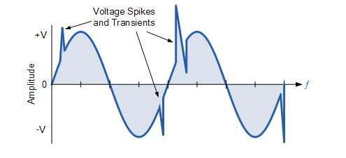
Figure 5: AC Waveform Transients
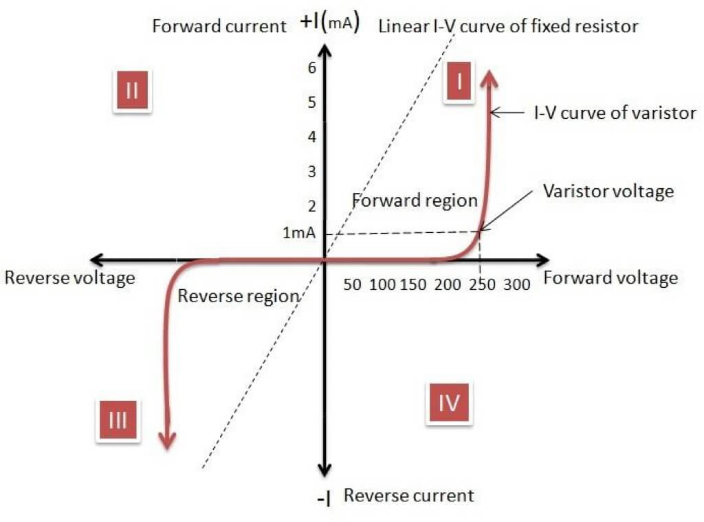
Figure 6: Varistor Characteristics Curve
Working Principle of Varistor
Varistors, hinging on the principle of non-linear volt-ampere characteristics, empower appliances with the capability to counter overvoltage scenarios in fractions of a second. This swift action not only curtails the voltage to a safeguarded domain swiftly but also shields the circuit's other components from the havoc wrought by abrupt voltage surges. Such rapid response, when allied with a significant design perk—minimal junction capacitance—positions the varistor as a potent antidote to overvoltage dilemmas.
In the realm of daily encounters, especially when it comes to defending high-frequency signal lines, the criteria for selecting and deploying varistors tighten. Despite their efficacy in overvoltage safeguarding, an oversized internal junction capacitance within the varistor could, paradoxically, impair high-frequency signals, diminishing signal integrity. Hence, the selection transcends mere considerations of response swiftness and voltage resilience; it also necessitates a vigilant examination of its repercussions on high-frequency signal fidelity.
Choosing a varistor for high-frequency pursuits demands an exhaustive scrutiny of the signal line's operational frequency alongside potential disruptors to signal transmission quality. Herein lies the essence of opting for a varistor with an apt junction capacitance value—a misstep in this selection can result in high-frequency signals being absorbed or reflected, thereby compromising signal quality.
Upon installation, the position of the varistor on the circuit board emerges as a critical concern. To mitigate interference with signal transmission while ensuring prompt overvoltage intervention, the varistor is ideally situated at a prudent distance from the high-frequency signal pathways. This meticulous approach, encompassing choice of varistor, strategic layout planning, and even the integrity of soldering, becomes intrinsically linked to the system's overall performance and dependability. This interplay of detailed selection and strategic installation underscores the nuanced complexity required to harness varistors effectively in safeguarding electronic circuits against overvoltage incidents.
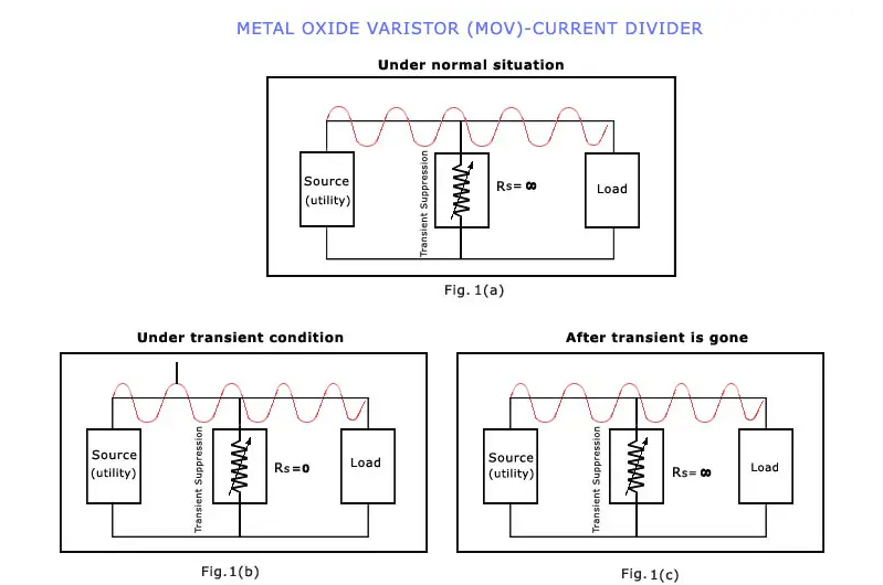
Figure 7: Working Principle of Metal Oxide Varistors (MOV)
The Application of Varistor
Varistors, standing as paramount shields, fiercely guard delicate circuits from the chaos transient voltages could unleash. They stand vigilant against the chaos transient voltages might unleash, becoming indispensable for both voltage stabilization and the detection of fluctuations. The design intricacies ensure they swiftly revert post-voltage surge, preserving performance and reliability over time. Not merely one-off protective elements, varistors are durable guardians, steadfast in their role.
Beyond their conventional role, varistors exploit their nonlinear traits for voltage regulation and detecting voltage level variations. In power supply design, a varistor shines as a dynamic voltage adjuster, ensuring steady output despite input volatility. Similarly, in safeguarding communication lines, varistors chosen for specific junction capacitance values excel, preventing disruption to high-frequency signal transmissions and highlighting their adaptability.
Varistors' utility transcends mere transient voltage protection. Their role in circuit safeguarding, voltage stability, and signal integrity is profound. Through thoughtful selection and application, they boost the stability and reliability of electronic devices, ensuring peak performance in varied conditions. The complexity and sudden shifts in sentence length underscore the intricate balance varistors maintain in electronic environments, reflecting their essential nature in modern technology.
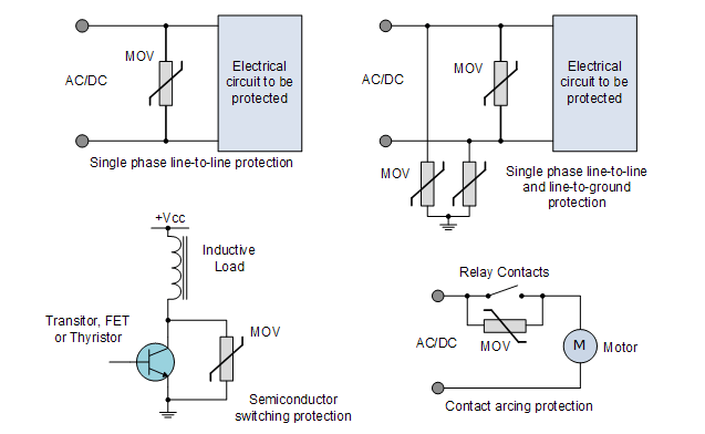
Figure 8: Varistor Applications
How to Test the Varistor?
To test the varistor, the initial step is to precisely measure its resistance, a task that requires the use of specialized equipment. By applying different voltages and measuring the resulting resistance, technicians plot the varistor’s volt-ampere characteristic curve. This essential action verifies whether the varistor’s nonlinear properties meet the expected standards and preliminarily checks for any signs of defects or damage, intertwining complexity, and anticipation in the evaluation.
Following this, the focus shifts to assessing the varistor’s protective effectiveness with a keen eye. A controlled, gradual increase in voltage, observed within the confines of a laboratory, tests the varistor's responsiveness. The moment the voltage at its terminals reaches a point where the varistor activates marks its protective threshold. This step, blending longer explanatory segments with concise conclusions, underscores the importance of a detailed evaluation to ascertain the varistor’s ability to defend the circuit reliably.
The evaluation process rigorously examines critical factors such as the maximum transient peak current, the ratio of residual voltage, and the varistor’s current handling prowess. Accurate measurements and thorough assessments of these parameters are indispensable, ensuring the varistor stands its ground against transient overvoltage scenarios without faltering under overload. Here, the complexity of the task is matched by the variability in sentence structure, enhancing the text’s depth.
When selecting a varistor, careful analysis is required of its compatibility with the rest of the circuit components, especially how its clamping voltage aligns with the capacitor. This stage is characterized by a detailed exploration of the circuit’s operating voltage, the types of transient voltages it might encounter, and how it transmits high-frequency signals. The objective is clear: to pinpoint the varistor model and specifications that are in perfect harmony with the circuit’s needs.
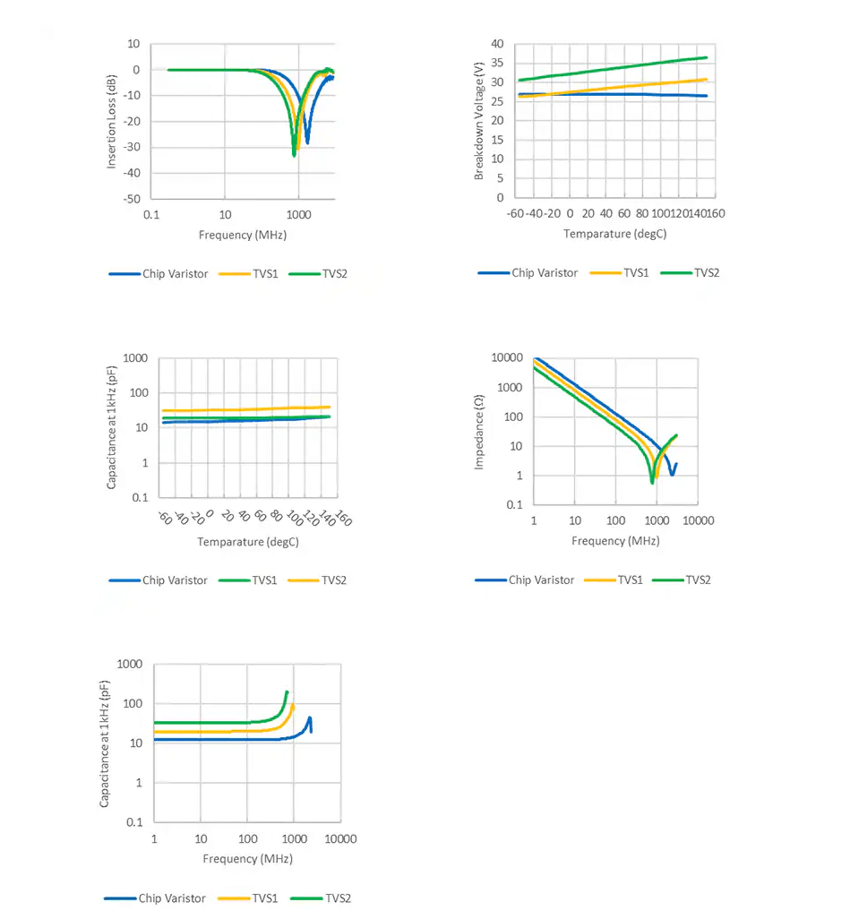
Figure 9: Comparative Test of Varistor and TVS Tube
Advantages and Disadvantages of Varistor
Varistors carve their niche in the protection component domain, acclaimed for their swift reaction time, bidirectional protection, and unmatched reliability, all while being economically viable. Instantaneously, these devices spring into action at the first hint of overvoltage, rapidly driving down the voltage to a haven, thus shielding circuits from potential damage. Their bidirectional trait ensures safeguarding against surges from any direction, marking them as pivotal for a plethora of applications.
However, varistors also have limitations. In the face of exceptionally high-energy surges, their efficacy and durability might falter. The heat they generate in such circumstances if left unchecked, could erode their dependability, gradually undermining the circuit's stability. It's here that the criticality of embedding sophisticated thermal management techniques in the design stage shines—be it through the incorporation of heat-dissipating elements or the selection of higher-grade varistors to better distribute the thermal load.
Technicians, with a keen eye on variables such as ambient temperature, the circuit's compact nature, and the extent of power lines, meticulously craft thermal management solutions that resonate with the unique demands of the application. In the realm of high-energy surges, marrying varistors with complementary protective allies like gas discharge tubes (GDTs) or transient voltage suppression diodes (TVS) emerges as a strategy to architect a robust protection ensemble.
Conclusion
Varistors stand as guardians in the electronic domain. Through thoughtful selection and deployment, they not only fortify circuits against transient voltages but also bolster the enduring and dependable operation of electronic devices in diverse settings. As we march forward, the evolution of electronic technologies and the expanding range of application spheres signal further sophistication in varistor design and application. This progression, aimed at meeting escalated protection needs and accommodating wider application landscapes, continues to fortify our electronic realm against looming threats.
Frequently Asked Questions [FAQ]
1. What is the lifespan of a varistor?
Under normal operating conditions and without continuous exposure to extreme voltage fluctuations, the life of a varistor can reach several years or even more than ten years. However, frequent large current surges or high-temperature environments will shorten its life.
2. How to read the varistor?
This is accomplished by using a multimeter to measure the ohm scale.
3. Should the varistor be placed before or after the fuse?
The varistor should usually be placed before the fuse, i.e. close to the power supply terminal.
4. Why does the varistor burn out?
Varistors can burn out due to factors such as withstanding current or voltage exceeding their maximum limits, being exposed to high temperatures for long periods, or due to manufacturing defects.
5. What is the maximum DC voltage of the varistor?
The maximum DC voltage (VDC) of a varistor varies depending on the model and manufacturer's specifications. Common values may range from tens of volts to several thousand volts, and the device data sheet should be consulted for specific values.
6. How to choose the varistor value?
When selecting a varistor, consider the circuit's operating voltage, expected maximum transient voltage, required protection voltage level, and current-carrying capability. Select a varistor whose protection voltage (clamping voltage) is slightly higher than the normal operating voltage of the circuit, while ensuring that its maximum transient peak current is greater than the maximum inrush current that may be encountered.
7. How to know if the resistor has failed?
By using a multimeter to measure its resistance value, if the resistance value is found to be infinite (open circuit) or close to zero (short circuit), it indicates that the varistor may have failed.
8. What is the difference between a capacitor and a varistor?
A capacitor is a component used to store electric charge, and its operation does not depend on changes in voltage, while the resistance value of a varistor changes with changes in voltage and is used to protect the circuit from overvoltage damage. Capacitors are mainly used for signal coupling, filtering, or energy storage, while varistors are used for overvoltage protection.
9. What is the response time of the varistor?
The response time of the varistor is very fast, generally at the nanosecond level (ns). This means they can react almost instantaneously to overvoltage events, providing immediate protection.