SS8050 NPN Epitaxial Silicon Transistor: High Performance for Small Signal Amplification and Switching
In the world of semiconductors, triodes—often referred to as bipolar transistors—stand as initial components in modern electronics. Their ability to regulate and amplify electrical currents makes them requisite in a wide range of applications, from analog signal amplification to efficient switching in digital circuits. In this article, we turn our focus to the SS8050, an NPN epitaxial silicon transistor known for its versatility and reliability in low-power amplification and switching tasks. We will explore its structure, characteristics, and practical uses, digging into why the SS8050 is a trusted choice for both everyday electronics and more complex systems. Whether you're interested in its high-frequency performance or its role in amplifying audio signals, this guide will provide a comprehensive look at what makes the SS8050 a dangerous component in modern electronics design.Catalog
Overview of the SS8050 Transistor
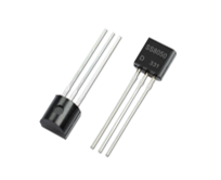
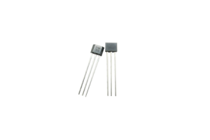
The SS8050 is a versatile NPN low-power, general-purpose transistor often used in amplification and switching tasks. It pairs with its complementary PNP counterpart, the SS8550, to form a complete transistor duo. Enclosed in a TO-92 casing, it exhibits notable features such as high current amplification, low noise, and remarkable high-frequency performance.
Structurally, the SS8050 consists of three regions: the N-type emitter, P-type base, and N-type collector. These regions highlight its significance as a bipolar junction transistor with exceptionally efficient current amplification capabilities. The robust electrical properties of the SS8050 make it well-suited for an array of low-power applications, including audio amplifiers and switching circuits.
The capability of the SS8050 to perform under low noise conditions makes it a cherished component in audio frequency applications, ensuring pristine sound quality without extraneous disturbances. Beyond its prowess in audio applications, the SS8050's stellar high-frequency performance allows it to thrive in communication devices, enhancing its functionality.
SS8050 Transistor Replacements
- MPS650G
- MPS651
- MPS8050
- S9013
- 2N5551
- 2N5830
Technical Specifications of SS8050
The SS8050, crafted by reputable manufacturers Onsemi and Fairchild, stands as a flexible and dependable NPN transistor. Its balance of performance and practicality see it adopted in a multitude of electronic applications. Delving into its technical specifications exposes its strengths and ideal use scenarios. Encased in a SOT-23-3 package, the SS8050 is appreciated for its compact, yet effective design.
These are the precise dimensions of this case.
- Length: 4.58 mm
- Width: 3.86 mm
- Height: 4.58 mm
These measurements make it apt for numerous through-hole mounting applications, especially when space is limited. The design of the TO-92-3 case also promotes efficient heat dissipation, maintaining the transistor's reliability across various operational environments.
Power Dissipation
The SS8050 boasts a power dissipation rating of 1 W. This rating denotes the highest amount of power the transistor can disperse without breaching thermal boundaries. In circuits where the transistor might endure varying loads, this characteristic helps keep performance steady and prevents overheating. Observations reveal that adhering to power dissipation limits extends the transistor's operational lifespan and curtails failure rates.
Collector Current
Supporting a continuous collector current of 1.5 A, the SS8050 is well-suited for driving moderate loads. These include small motors, LEDs, and other components that require a steady current flow. Its ability to manage this current reliably makes it a preferred option in both consumer electronics and industrial applications.
Temperature Range
The SS8050 runs efficiently within a temperature range from -65°C to 150°C, showcasing its robustness in diverse conditions. This extensive range allows it to be deployed in various climates, handling both extreme cold and momentous heat. Using components within their specified temperature ranges not only offers better performance but also ensures longevity, as extremes can undermine electronic stability and reliability.
NPN vs. PNP Transistors
NPN Transistor (SS8050)
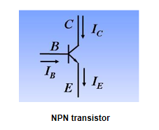
For the SS8050 transistor, the current relationship follows IE = IC + IB. By grounding the three pins, you can dissect its operational states.
Amplified State - The condition VC > VB > VE signifies an amplified state where the emitter is positive-biased and the collector is reverse-biased. This configuration propels the transistor's ability to amplify signals, carving its indispensable role in enhancing audio in consumer electronics and refining signals in communication devices.
Saturation State - In this mode, where VB > VC > VE, both the emitter and collector are positive-biased. This condition drives the transistor into saturation, allowing maximum current to gush from the collector to the emitter. This state is exploited in switch-mode power supplies and digital logic circuits where agile switching is active.
Cutoff State - The state VB > VE > VC indicates that both the emitter and collector are reverse-biased. In this mode, negligible current flows through, effectively switching off the transistor. This behavior ensures clear on/off states in digital circuits, fostering reliable logic operations. Hence, switches and relays deploy this mode to control power flow efficiently.
PNP Transistor (SS8550)
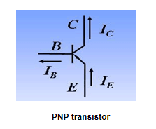
For the SS8550 transistor, the current relationship follows IC = IE + IB. By grounding the three pins, its operational states can be identified.
Amplified State - In this mode, VE > VB > VC, the emitter is positive-biased and the collector is reverse-biased. The transistor operates in its amplification region, akin to the NPN transistor but with inverted polarity. This state is leveraged in analog circuits, such as voltage regulation systems, where stable output signals are dominant.
Saturation State - When VE > VC > VB, both the emitter and collector are positive-biased. The PNP transistor allows maximum current flow from the emitter to the collector in this state. It's highly suited for circuits that demand quick transitions between on and off states, such as power management systems and motor control applications.
Cutoff State - The condition VB > VE > VC signifies that both the emitter and collector are reverse-biased. This places the transistor in the cutoff state, resulting in no substantial current flow, thus turning off the transistor. Practically, this behavior is required for efficient power delivery control in electronic devices, ensuring energy conservation and staving off redundant power use.
Implementing the SS8050 Transistor
The SS8050 transistor is versatile and widely used in amplification, switching, and regulation circuits. It commonly appears in power management systems and audio amplifiers. Below are some detailed insights and strategies to maximize its effectiveness:
Operating State
The choice of operating state—whether it's amplification, saturation, or cutoff—depends on the specific application. Maintaining the transistor in its active region can enhance an amplifier’s performance. For switching applications, toggling between saturation and cutoff states is advantageous. Many experienced technicians believe that meticulous calibration of the operating point not only elevates system efficiency but also enhances its reliability.
Polarity Verification
Accurately verifying polarity and pin connections ensures proper operation. Identifying the collector (marked "C") and emitter (marked "E") correctly is suitable to prevent circuit malfunctions. Typically, multimeters during circuit assembly to confirm these connections, reducing the risk of errors and ensuring stable performance.
Circuit Connection
Various configurations are possible when integrating the SS8050 transistor into circuits.
Common Emitter Configuration - This setup is frequently used in power amplifiers to suggestively boost power output while maintaining signal integrity. Accurate biasing of the base-emitter junction is dynamic for efficient operation and is typically achieved through a stable voltage divider network.
Common Collector Configuration - Known for its voltage-following properties, this configuration is instrumental in providing impedance matching in circuits. This setup is in buffer stages to maintain signal amplitude, which is used for preserving the fidelity of the transmitted signal.
Common Base Configuration - Preferred for high-frequency applications, the common base configuration offers minimal input impedance and high bandwidth Often this setup in RF amplifiers ensures superior frequency response with minimal loss and distortion at higher frequencies.
Electrical Properties of the SS8050
|
Symbol |
Parameter |
Conditions |
Min. |
Typ. |
Max. |
Unit |
|
BVCBO |
Collector-Base Breakdown Voltage |
IC = 100 µA, IE = 0 |
40 |
V |
||
|
BVCEO |
Collector-Emitter Breakdown Voltage |
IC = 2 mA, IB = 0 |
25 |
V |
||
|
BVEBO |
Emitter-Base Breakdown Voltage |
IE = 100 µA, IC = 0 |
6 |
V |
||
|
ICBO |
Collector Cut-Off Current |
VCB = 35 V, IE = 0 |
100 |
nA |
||
|
IEBO |
Emitter Cut-Off Current |
VEB = 6 V, IC = 0 |
100 |
nA |
||
| hFE1 |
DC Current Gain |
VCE = 1 V, IC = 5 mA |
45 |
|||
|
hFE2 |
VCE = 1 V, IC = 100 mA |
85 |
300 |
|||
|
hFE3 |
VCE = 1 V, IC = 800 mA |
40 |
||||
|
VCE(sat) |
Collector-Emitter Saturation Voltage |
IC = 800 mA, IB = 80 mA |
0.5 |
V |
||
|
VBE(sat) |
Base-Emitter Saturation Voltage |
IC = 800 mA, IB = 80 mA |
1.2 |
V |
||
|
VBE(on) |
Base-Emitter On Voltage |
VCE = 1 V, IC = 10 mA |
1 |
V |
||
|
Cob |
Output Capacitance |
VCB = 10 V, IE = 0, f = 1 MHz |
9.0 |
pF |
||
|
fT |
Current Gain Bandwidth Product |
VCE = 10 V, IC = 50 mA |
100 |
MHz |
SS8050 vs. S8050
When diving into the SS8050 and S8050, it becomes intriguing to explore their electrical characteristics and practical applications for a better appreciation of these components.
Electrical Properties
Examining the electrical properties of the SS8050 and S8050 reveals differences that influence their usage in various designs.
The voltage of the SS8050 is 30 V while the S8050 voltage is 40 V. This higher voltage capacity of the S8050 makes it more fitting for circuits requiring a greater breakdown voltage. The Current Gain of SS8050 ranges from 120 to 300 while S8050 ranges from 60 to 150. A higher current gain in the SS8050 often signifies better amplification capabilities, making it preferable in applications that need a substantial signal boost.
Applications
The SS8050 finds its place in AC power supply circuits. Its momentous current gain and distinct voltage rating make it ideal for scenarios where robust amplification and stable performance at relatively higher voltages are wanted. For example, power amplifiers in audio systems frequently use transistors like the SS8050 to ensure exemplary performance and clear sound quality.
On the other hand, the S8050 is apt for low-voltage, low-power applications, such as alarms and simple switching circuits. Its lower maximum voltage and moderate current gain fit well with devices that do not demand high power or extensive amplification. For instance, security systems often implement S8050s in sensor circuits, providing reliable operation with minimal power consumption.
Packaging
The physical packaging of these transistors can also affect their integration into different hardware designs.
The SS8050 is typically available in a SOT-23 package. This packaging type is beneficial for compact, surface-mount designs, making it a preferred choice in modern electronic devices aiming for miniaturization.
The S8050 usually comes in a TO-92 package. This larger package is more suitable for through-hole PCB applications, offering ease of handling and installation, especially during prototyping stages and when robust mechanical support is a must.
Testing the SS8050 Transistor
To assess the functionality of the SS8050 transistor start with a multimeter set to diode test mode and measure the resistance between the base-emitter and the base-collector junctions. Connect the red probe to the base and the black probe to either the emitter or the collector. You should observe a voltage drop, typically between 0.6V and 0.7V. This voltage drop indicates the proper functioning of the transistor junctions. Upon reversing the probes, the multimeter should display an infinite resistance, affirming the transistor’s health.
Beyond basic testing, practical experiences reveal additional distinctions in evaluating transistors. Environmental factors such as temperature can influence readings. These details often become evident during fieldwork in varying climatic conditions. Adjusting test protocols for these environmental factors ensures accurate results. Repeated tests might reveal subtle inconsistencies that warrant further investigation, highlighting the importance of meticulous observation.
The SS8050 transistor is valued for its affordability and simplicity, making it a frequent choice in numerous electronic projects, and its ability to handle moderate power loads without substantial heat dissipation issues, a trait often observed during long-term usage in diverse applications. This consistency makes the SS8050 reliable for tasks such as signal amplification and switching operations in low-power circuits.
Frequently Asked Questions [FAQ]
1. What can replace SS8050?
Possible replacements for SS8050 include MPS650, MPS650G, MPS651, MPS651G, and MPS8050. When selecting a substitute, scrutinize parameters like voltage, current rating, and gain to ensure compatibility. For instance, the MPS8050 shares similar electrical characteristics and can serve as a direct replacement in most circuits, maintaining the circuit's integrity and performance.
2. What are the uses of SS8050?
SS8050 is widely applied in audio amplification, and various electronic circuits (e.g., switching applications). This device shines in scenarios requiring low to medium power amplification, offering efficient signal transmission. For example, in audio equipment, SS8050 ensures sound amplification by efficiently boosting weak audio signals, providing a clearer audio experience.
3. Difference between S8050 and S8550?
The S8050 and S8550 transistors differ primarily in their conduction behavior. An S8050 circuit activates a load, such as a light, when a button is pressed, promoting high-level conduction while an S8550 circuit activates the load when the button is released, allowing for low-level conduction. This difference stems from their distinct NPN and PNP nature, impacting their functionality in control circuits. Each transistor type manages the on and off states of connected devices based on their unique conduction properties.
4. Main applications of SS8050?
SS8050 is extensively employed in amplification tasks, switching in electronic circuits, audio amplifiers, signal amplification, and low to medium power switching. Its role in audio amplifiers is mostly noteworthy, as it enhances sound quality by boosting weak audio signals. The transistor's use in signal amplification circuits emphasizes its versatility and effectiveness in maintaining signal clarity and integrity across diverse electronic applications.
About us
ALLELCO LIMITED
Read more
Quick inquiry
Please send an inquiry, we will respond immediately.
A Guide to the A3144 Magnetic Hall Effect Sensor
on September 25th
TDA7850 Audio Amplifier: Power and Performance
on September 25th
Popular Posts
-

What is GND in the circuit?
on January 1th 3272
-

RJ-45 Connector Guide: RJ-45 Connector Color Codes, Wiring Schemes, R-J45 Applications, RJ-45 Datasheets
on January 1th 2815
-

Understanding Power Supply Voltages in Electronics VCC, VDD, VEE, VSS, and GND
on November 20th 2640
-

Fiber Connector Types: SC Vs LC And LC Vs MTP
on January 1th 2265
-

Comparison Between DB9 and RS232
on January 1th 1882
-

What Is An LR44 Battery?
Electricity, that ubiquitous force, quietly permeates every aspect of our daily lives, from trivial gadgets to life-threatening medical equipment, it plays a silent role. However, truly grasping this energy, especially how to store and efficiently output it, is no easy task. It is against this background that this article will focus on a type of coin cell battery that may seem insignificant on the...on January 1th 1846
-

Understanding the Fundamentals:Inductance Resistance, andCapacitance
In the intricate dance of electrical engineering, a trio of fundamental elements takes center stage: inductance, resistance, and capacitance. Each bears unique traits that dictate the dynamic rhythms of electronic circuits. Here, we embark on a journey to decipher the complexities of these components, to uncover their distinct roles and practical uses within the vast electrical orchestra. Inductan...on January 1th 1808
-

What Is RF and Why Do We Use It?
Radio Frequency (RF) technology is a key part of modern wireless communication, enabling data transmission over long distances without physical connections. This article delves into the basics of RF, explaining how electromagnetic radiation (EMR) makes RF communication possible. We will explore the principles of EMR, the creation and control of RF signals, and their wide-ranging uses. The article ...on January 1th 1801
-

CR2430 Battery Comprehensive Guide: Specifications, Applications and Comparison to CR2032 Batteries
What is CR2430 battery ?Benefits of CR2430 BatteriesNormCR2430 Battery ApplicationsCR2430 EquivalentCR2430 VS CR2032Battery CR2430 SizeWhat to look for when buying the CR2430 and equivalentsData Sheet PDFFrequently Asked Questions Batteries are the heart of small electronic devices. Among the many types available, coin cells play a crucial role, commonly found in calculators, remote controls, and ...on January 1th 1799
-

Comprehensive guide to hFE in transistors
Transistors are crucial components in modern electronic devices, enabling signal amplification and control. This article delves into the knowledge surrounding hFE, including how to select a transistor's hFE value, how to find hFE, and the gain of different types of transistors. Through our exploration of hFE, we gain a deeper understanding of how transistors work and their role in electronic circu...on November 20th 1782
HOT Part Number
-

CL03C0R3BA3GNNH
Samsung Electro-Mechanics
CAP CER 0.3PF 25V NP0 0201
ILD256T
Vishay Semiconductor Opto Division
OPTOISOLTR 4KV 2CH TRANS 8-SOIC
ZMM5243B-7
Diodes Incorporated
DIODE ZENER 13V 500MW MINI MELF
FAN6206MY
onsemi
IC REG CTRLR ACT/SYNC 8SOIC
06036D474MAT2A
KYOCERA AVX
CAP CER 0.47UF 6.3V X5R 0603
74ACT00SC
onsemi
IC GATE NAND 4CH 2-INP 14SOIC
MCP4012T-202E/CH
Microchip Technology
IC DGT POT 2.1KOHM 64TAP SOT23-6
BZX55C30
Taiwan Semiconductor Corporation
DO-35, 500MW, 5%, SMALL SIGNAL Z
NSVMUN5314DW1T3G
onsemi
TRANS NPN/PNP 50V BIPO SC88-6
TPS543B20RVFR
Texas Instruments
IC REG BUCK ADJ 25A 40LQFN
181M-01LFT
Renesas Electronics America Inc
IC SS CLOCK GENERATOR 8SOIC
CC0603KRNPO9BN271
YAGEO
CAP CER 270PF 50V C0G/NPO 0603
LTC4150IMS#TRPBF
Analog Devices Inc.
IC BAT MON MULT-CHEM 1-6C 10MSOP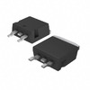
STB60N55F3
STMicroelectronics
MOSFET N-CH 55V 80A D2PAK
R5F10KBCAFP#V0
Renesas Electronics America Inc
IC MCU 16BIT 32KB FLASH 32LQFP
GCM1885C1H101JA16J
Murata Electronics
CAP CER 100PF 50V C0G/NP0 0603
IRFS4321TRLPBF
Infineon Technologies
MOSFET N-CH 150V 85A D2PAK
GRM155C70J225KE11D
Murata Electronics
CAP CER 2.2UF 6.3V X7S 0402 -
ACPL-064L-560E
Broadcom Limited
OPTOISO 3.75KV 2CH PUSH PULL 8SO
TAJD106M035RNJ
KYOCERA AVX
CAP TANT 10UF 20% 35V 2917
TMP102AIDRLRG4
Texas Instruments
SENSOR DIGITAL -40C-125C SOT563
MM74HC86M
onsemi
IC GATE XOR 4CH 2-INP 14SOIC
GRM1885C2A6R3DA01D
Murata Electronics
CAP CER 6.3PF 100V C0G/NP0 0603
LTC7862EFE#PBF
Analog Devices Inc.
SURGE SUPP SWITCHING 20TSSOP
HZM4.3NB3TL-E
Renesas Electronics America Inc
DIODE ZENER
GRM0225C1E3R8WDAEL
Murata Electronics
CAP CER 3.8PF 25V C0G/NP0 01005
TNY253GN-TL
Power Integrations
IC OFFLINE SWITCH FLYBACK 8SMD
XLP208B0IFSB00120G
Broadcom Limited
FCBGA+HS 29
PM3316-330M-RC
Bourns Inc.
FIXED IND 33UH 1.8A 120 MOHM SMD
CL05B562KO5NNNC
Samsung Electro-Mechanics
CAP CER 5600PF 16V X7R 0402
MAX1822ESA+T
Analog Devices Inc./Maxim Integrated
IC REG CHARGE PUMP VIN+11V 8SOIC
AT25256AW-10SU-2.7
Microchip Technology
IC EEPROM 256KBIT SPI 8SOIC
MIC22400YML-TR
Microchip Technology
IC REG BUCK ADJUSTABLE 4A 20MLF
GRM1887U1H512JA01D
Murata Electronics
CAP CER 5100PF 50V U2J 0603
06031A530JAT2A
KYOCERA AVX
CAP CER 53PF 100V NP0 0603
ISL8702IBZ-T
Renesas Electronics America Inc
IC SUPERVISOR 4 CHANNEL 14SOIC -

XC7K325T-1FFG676C
AMD
IC FPGA 400 I/O 676FCBGA
LM385DR-2-5
Texas Instruments
IC VREF SHUNT 3% 8SOIC
AOTF29S50L
Alpha & Omega Semiconductor Inc.
MOSFET N-CH 500V 29A TO220-3F
Z8401510FEC
Zilog
IC MPU Z80 10MHZ 100QFP
CP2102N-A02-GQFN28
Silicon Labs
IC USB TO UART BRIDGE QFN28
AD5446YRMZ-RL7
Analog Devices Inc.
IC DAC 14BIT A-OUT 10MSOP
ME601615
Powerex Inc.
BRIDGE RECT 3P 1.6KV 150A MODULE
LCD30-24S3P3W
P-DUKE Technology, Inc.
DC DC CONVERTER 3.3V 23W
GRM0335C1E6R0DD01D
Murata Electronics
CAP CER 6PF 25V C0G/NP0 0201
UCC2818ADR
Texas Instruments
IC PFC CTR AVERAGE 220KHZ 16SOIC
STW69N65M5
STMicroelectronics
MOSFET N-CH 650V 58A TO247
DZ2S07500L
Panasonic Electronic Components
DIODE ZENER 7.51V 150MW SSMINI2
GRM0335C1H330JD01J
Murata Electronics
CAP CER 33PF 50V C0G/NP0 0201
CM75DU-24F
Powerex Inc.
IGBT MOD 1200V 75A 450W
MSP430F2618TPN
Texas Instruments
IC MCU 16BIT 116KB FLASH 80LQFP
TLV2556IDWR
Texas Instruments
IC ADC 12BIT SAR 20SOIC
HFW1201K45M
TE Connectivity Aerospace, Defense and Marine
RELAY GEN PURPOS DPDT 2A 26.5VDC
PIC24HJ32GP302-I/SP
Microchip Technology
IC MCU 16BIT 32KB FLASH 28SPDIP