Understanding the Key Features and Applications of ULN2003
ULN2003 is a high-voltage, high-current composite transistor array series product. It has high operating voltage, high current gain, wide temperature range and strong load capacity, so it is very suitable for various systems that require high-power drive. This article will introduce relevant information of ULN2003, including its characteristics, pins and functions, working principle, function and application. Let's start.Catalog
ULN2003 Overview
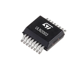
ULN2003 is a high-voltage and high-current driver that is commonly used in various circuits for electronic lock control, motor drive, stepper motor drive, LED display conversion, smart home equipment, and other occasions where high-voltage and high-current devices need to be controlled. It consists of seven silicon NPN composite transistors, with each pair of Darlington transistors connected in series with a 2.7K base resistor. At an operating voltage of 5V, it can be directly connected to TTL and CMOS circuits, so it can directly process data that originally required standard logic buffers. Therefore, ULN2003 can control multiple devices simultaneously. It has the advantages of high reliability, convenient interface, etc., and is easy to be integrated into various circuits.
Alternatives and Equivalents
• LR2003L
• ULN2001
• ULN2001A
• ULN2003A
What Are the Characteristics of ULN2003?
ULN2003 has the following features:
• Shallow sleep current: When the output is low, the sleep current of the ULN2003 is very low, which helps reduce power consumption and heat generation.
• DIP package: ULN2003 adopts dual in-line package for easy insertion into the circuit board and easy soldering.
• Seven programmable outputs: The ULN2003 has seven output pins, each of which can be controlled independently, making it ideal for driving multiple motors or relays.
• Input and control level compatibility: The input pins of ULN2003 adopt TTL and CMOS level control, which are fully compatible with common logic levels, so it is very convenient to integrate with other digital circuits.
• Built-in free DuPont diode: Each Darlington pair has built-in free DuPont diode to protect the switching components from reverse voltage damage, thereby improving the reliability of the chip.
• High current and high voltage: The output of ULN2003 can withstand high current and voltage. Its maximum withstand current is 500mA and the maximum withstand voltage is 50V, which makes it very suitable for controlling high-power motors and relays.
Pin Diagram and Functions of ULN2003
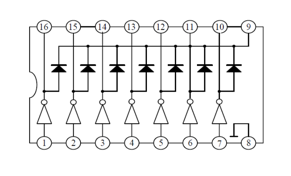
Pin 1: This pin is the pulse input terminal of the CPU, and the port corresponds to a signal output terminal.
Pin 2 to 7: This pin is the CPU pulse input terminal.
Pin 8: This pin is grounded.
Pin 9: This pin is the common cathode of the seven internal freewheeling diodes. The anode of each diode is connected to the collector of each Darlington tube. When used for inductive loads, this pin should be connected to the positive pole of the load power supply to achieve freewheeling. If this pin is connected to ground, it is actually equivalent to the collector of the Darlington tube being connected directly to ground.
Pins 10 to 16: These pins are the pulse signal output terminals, corresponding to the pin 7, pin 6, pin 5, pin 4, pin 3, pin 2, and pin 1 signal input terminals respectively.
Working Principle and Function of ULN2003
The ULN2003 consists of two main parts, the input side and the output side. The inputs include seven input pins (IN1 to IN7), which are used to receive logic signals from external sources, while the outputs contain seven switching tube output ports (OUT1 to OUT7), which are responsible for controlling the switching state of the load circuits.
The working principle of ULN2003 is as follows: when the input signal is high level, the corresponding switch tube inside the chip will be in a closed state, and the load circuit cannot be driven by current at this time; when the input signal is low level, the switch tube will be turned on, thus allowing current to drive the load circuit. Therefore, by changing the level state of the input terminal, we can achieve switching control of the corresponding pin of the output terminal.
The main function of ULN2003 is to drive high voltage, high current, and high inductance loads. Since ordinary microcontrollers cannot directly control these loads, ULN2003 is required for driving and control. In addition, the chip is equipped with an internal suppression diode to provide reverse protection at the output port, making the entire system more stable and reliable.
ULN2003 Drive Circuit Diagram
ULN2003 is an integrated circuit with 16 pins. It integrates seven pairs of Darlington transistors, each capable of driving loads up to 50V and 500mA. For these seven Darlington pairs, we equip the corresponding seven input and output pins. In addition, it contains ground pins and general purpose pins. Typically, the ground pin is connected directly to ground, while the use of a common pin is optional. Surprisingly, this IC does not have a dedicated Vcc pin. This is because the power required for the transistor to operate will be drawn directly from the input pin. Below is a simple circuit example that can be used to test the operation of the ULN2003 integrated circuit.
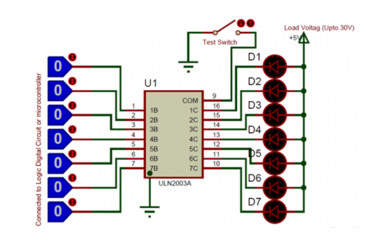
In the circuit, we think of the LED as the load and the logic pins are used to connect to digital circuits or microcontrollers like Arduino. Note that the positive pin of the LED should be connected to the positive load voltage and the negative pin should be connected to the output pin of the IC. This is because when the input pin level of the IC goes high, the corresponding output pin goes to ground. Therefore, when the negative terminal of the LED is connected to ground, the circuit is closed, allowing the LED to emit light. The maximum load current connected to each output pin is 500mA and the voltage is 50V. However, if you need to drive a higher current load, you can do so by connecting two or more output pins in parallel. For example, if you connect three pins in parallel, you can drive about 1.5A. The COM pin is used to connect to ground through the switch, this connection is optional. It can be used as a test switch, i.e. when this pin is connected to ground, all output pins will be connected to ground.
Where Is ULN2003 Used?
In practical applications, ULN2003 is often used to drive inductive loads such as stepper motors, relays, and solenoid valves. Since these loads usually require larger currents and higher voltages to drive, ULN2003 has sufficient driving capabilities while having smaller power consumption and higher reliability, making it an ideal choice for driving these loads.
In addition to the basic driving function, ULN2003 can also realize more complex control functions by using external resistors, capacitors, and other components. For example, we can use external resistors to adjust the size of the output current, or through external capacitors to realize the de-jitter and other functions. The realization of these control functions not only further broadens the scope of application of ULN2003, but also enhances the flexibility of its use.
In the design and manufacturing process of electronic equipment, ULN2003 is widely used. It can be used in various control circuits, drive circuits, protection circuits, and other occasions, providing an important guarantee for the normal operation of electronic equipment. At the same time, because ULN2003 has a smaller size and lower power consumption, it has also been widely used in electronic devices that pursue miniaturization and low power consumption.
How to Use ULN2003 to Drive Stepper Motor?
First, we need to connect the power supply of the stepper motor to an appropriate supply voltage and make sure that the supply voltage range of ULN2003 meets the requirements of the stepper motor. Next, we connect the output pins of the ULN2003 to the controls of the stepper motor. Typically, stepper motors have four control lines (A, A', B, B') corresponding to two phases. We connect each of the four outputs (OUT1 through OUT4) of the ULN2003 to these four control lines of the stepper motor. Subsequently, we connect a control signal (e.g. from a microcontroller) to the input of the ULN2003. When the input signal is high, the corresponding ULN2003 output pin will be pulled low, which will cause the stepper motor to rotate. We then need to write the program to control the stepper motor using an appropriate programming language. Depending on the type of stepper motor (single-phase, two-phase, four-phase, etc.), we need to determine the correct step sequence and control signals. Finally, we run the program and test the motion of the stepper motor. As needed, we can adjust the step sequence and speed of the stepper motor to ensure that it operates as expected.
Frequently Asked Questions [FAQ]
1. What replaces ULN2003 Mosfet?
We do have a mosfet equivalent to the ULN2003, called the TPL7407LA.
2. What is ULN2003 used for?
ULN2003 IC is one of the most commonly used Motor driver IC. This IC comes in handy when we need to drive high current loads using digital logic circuits like Op-maps, Timers, Gates, Arduino, PIC, ARM etc.
3. What is ULN2003 chip?
ULN2003 Driver Module is a Stepper Motor Driver, small size and easy to use. It uses the ULN2003 driver chip to amplify the control signal from the Arduino. This Ultra Lightweight and cheap option commonly used to run and control the small applications stepper motors.
4. Why we use ULN2803?
The ULN2803 integrated circuit is used as a power interface for circuits with CMOS and TTL technology. This integrated has 8 NPN transistors in Darlington configuration with protection diodes, to control motors, inductive loads, relays, and more.
5. What is the difference between ULN2002 and ULN2003?
The ULN2002A is specifically designed for use with 14- to 25-V PMOS devices. Each input of this device has a zener diode and resistor in series to control the input current to a safe limit. The ULN2003A has a 2.7-kΩ series base resistor for each Darlington pair for operation directly with TTL or 5-V CMOS devices.
About us
ALLELCO LIMITED
Read more
Quick inquiry
Please send an inquiry, we will respond immediately.
Exploring the NE555 Timer IC: Key Features, Design Principles, and Real-World Applications
on September 3th
How to Effectively Utilize LM324N in Analog Circuits: Applications and Power Supply Configuration
on September 3th
Popular Posts
-

What is GND in the circuit?
on January 1th 3124
-

RJ-45 Connector Guide: RJ-45 Connector Color Codes, Wiring Schemes, R-J45 Applications, RJ-45 Datasheets
on January 1th 2679
-

Understanding Power Supply Voltages in Electronics VCC, VDD, VEE, VSS, and GND
on November 15th 2228
-

Fiber Connector Types: SC Vs LC And LC Vs MTP
on January 1th 2187
-

Comparison Between DB9 and RS232
on January 1th 1804
-

What Is An LR44 Battery?
Electricity, that ubiquitous force, quietly permeates every aspect of our daily lives, from trivial gadgets to life-threatening medical equipment, it plays a silent role. However, truly grasping this energy, especially how to store and efficiently output it, is no easy task. It is against this background that this article will focus on a type of coin cell battery that may seem insignificant on the...on January 1th 1778
-

Understanding the Fundamentals:Inductance Resistance, andCapacitance
In the intricate dance of electrical engineering, a trio of fundamental elements takes center stage: inductance, resistance, and capacitance. Each bears unique traits that dictate the dynamic rhythms of electronic circuits. Here, we embark on a journey to decipher the complexities of these components, to uncover their distinct roles and practical uses within the vast electrical orchestra. Inductan...on January 1th 1731
-

CR2430 Battery Comprehensive Guide: Specifications, Applications and Comparison to CR2032 Batteries
What is CR2430 battery ?Benefits of CR2430 BatteriesNormCR2430 Battery ApplicationsCR2430 EquivalentCR2430 VS CR2032Battery CR2430 SizeWhat to look for when buying the CR2430 and equivalentsData Sheet PDFFrequently Asked Questions Batteries are the heart of small electronic devices. Among the many types available, coin cells play a crucial role, commonly found in calculators, remote controls, and ...on January 1th 1683
-

What Is RF and Why Do We Use It?
Radio Frequency (RF) technology is a key part of modern wireless communication, enabling data transmission over long distances without physical connections. This article delves into the basics of RF, explaining how electromagnetic radiation (EMR) makes RF communication possible. We will explore the principles of EMR, the creation and control of RF signals, and their wide-ranging uses. The article ...on January 1th 1672
-
Comprehensive guide to hFE in transistors
Transistors are crucial components in modern electronic devices, enabling signal amplification and control. This article delves into the knowledge surrounding hFE, including how to select a transistor's hFE value, how to find hFE, and the gain of different types of transistors. Through our exploration of hFE, we gain a deeper understanding of how transistors work and their role in electronic circu...on November 15th 1641
