Understanding Capacitors and Their Symbols in Circuit Diagrams
Capacitors are small parts used in almost all electronic devices. They store and release electrical energy and are found in things like power supplies, radios, and circuits that help reduce noise. To work with electronics, it's helpful to understand how capacitors are shown in circuit diagrams. This article will explain what capacitors are, how they work, and how to read the symbols used for them in these diagrams. By learning about the different types of capacitors and their symbols, you'll be better able to understand how circuits work and how to properly use capacitors in them.Catalog

Figure 1: Capacitor Symbol
What Is a Capacitor?
A capacitor, sometimes called a condenser, is an electronic component that stores and releases electrical energy. Its primary function is to hold an electric charge and discharge it when required by the circuit. Capacitors consist of two conductive plates (usually metal) separated by an insulating material called a dielectric. The dielectric can be air, ceramics, polyester film, aluminum electrolyte, or other materials.
When voltage is applied to a capacitor, positive charges accumulate on one plate and negative charges on the other. This creates an electric field in the dielectric material between the plates, allowing the capacitor to store energy. Capacitors are used in a wide range of applications, from power supplies to radio circuits and noise filtering.
Overview of Capacitor Symbols
Capacitor symbols in circuit diagrams are simple drawings that show the part and how it works in the circuit. These symbols are made up of two straight lines next to each other, showing the two plates of the capacitor. There’s a space between the lines, representing the insulating material, called the dielectric, which separates the plates. This material stops direct current from moving between the plates but allows the capacitor to store electrical energy.
Polarized and Non-Polarized Capacitors
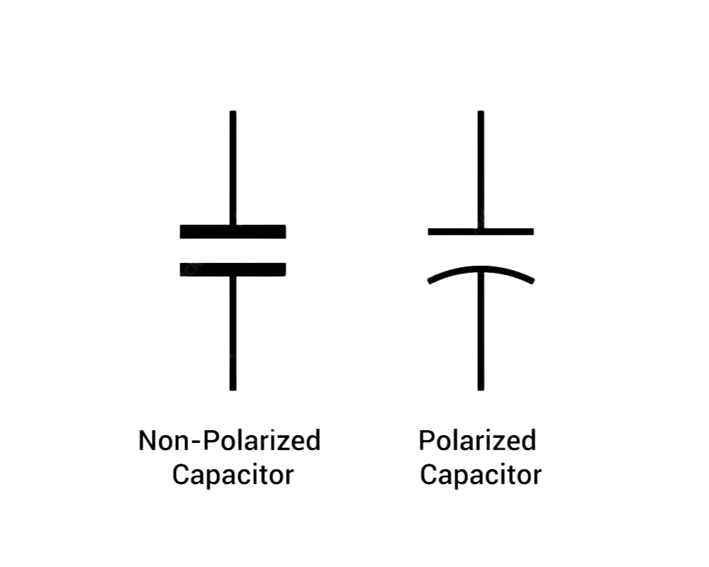
Figure 2: Non-Polarized and Polarized Capacitor Symbols
There are two main types of capacitors: non-polarized and polarized. Each type has a special symbol to show how it needs to be placed in a circuit.
Non-polarized capacitors are used in circuits where the current can go either way. Their symbol is two straight, parallel lines, showing that both sides are the same. These capacitors don't have a specific positive or negative side, so you can connect them in any direction, and they will still work as they should.
Polarized capacitors are different because they must be connected a certain way. They have a positive and a negative side. The symbol for these capacitors shows this difference by using one straight line for the positive side and either a curved line or a "+" sign to show which side is positive. This tells you which side of the capacitor needs to be connected to the positive part of the circuit. If you connect a polarized capacitor the wrong way, it can break or cause problems in the circuit.
Significance of Capacitor Symbols in Electrical Diagrams
Capacitor symbols in electrical diagrams show basic information about a capacitor, making it easier for engineers and technicians to understand what type of capacitor is being used and how it should be placed in a circuit. These symbols indicate whether the capacitor is polarized or non-polarized. A polarized capacitor needs to be installed in a specific direction, as putting it the wrong way can cause problems. Non-polarized capacitors, however, can be placed in any direction without issues.
The symbols also often display the capacitance value, which shows how much electrical charge the capacitor can hold. This value is important because different circuits need different amounts of charge to work properly. If the wrong value is chosen, the circuit might not work the way it's supposed to.
By using standard symbols for capacitors, everyone working on an electrical diagram can easily understand how the capacitor should be used. This helps avoid mistakes, such as picking the wrong capacitor or putting it in the wrong place, which could cause the circuit to stop working or become less reliable.
Types of Capacitor Symbols
Capacitors are small electronic components used in various circuits, and their symbols in diagrams change depending on the type of capacitor and its function. Learning these symbols is helpful for reading circuit diagrams properly. Capacitors are mainly divided into polarized, non-polarized, variable, and specialized types, each with its own unique symbol.
Polarized Capacitor Symbols
Polarized capacitors, like electrolytic capacitors, have a positive and a negative terminal. In circuit diagrams, they are shown with a symbol that makes it easy to see which side is positive and which is negative. A straight line usually represents the positive terminal, and a curved line or a "-" sign represents the negative terminal. Sometimes, a "+" sign is also added to show the positive side more clearly.
These capacitors are commonly used in circuits for tasks like filtering or reducing noise. The two main types of polarized capacitors are:
• Aluminum Electrolytic Capacitors
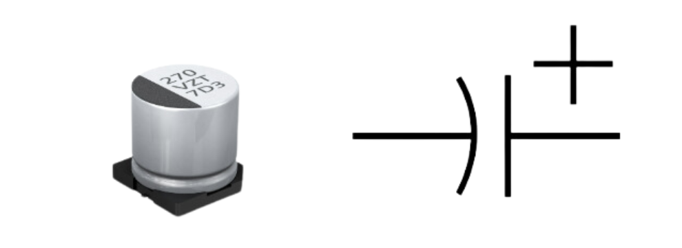
Figure 3: Aluminum Electrolytic Capacitor Symbol
These are commonly found in power supply circuits and audio systems because they can store a large amount of charge and are cheap. However, they have a shorter life span and may not perform well at higher temperatures.
• Tantalum Capacitors
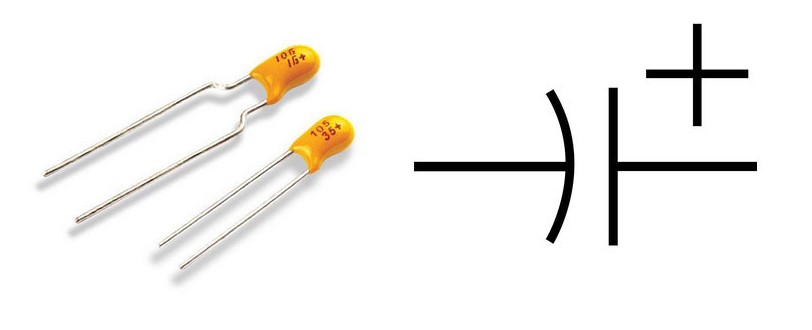
Figure 4: Tantalum Capacitor Symbol
Tantalum capacitors are more reliable and stable than aluminum ones, so they are often used in situations where high performance is needed, such as in medical equipment or aerospace electronics. They last longer and leak less current but tend to be more expensive.
Non-polarized Capacitor Symbols
Non-polarized capacitors, also called fixed capacitors, don’t have a positive or negative side. This means you can connect them in any direction in the circuit, and they will still work. Their symbol in diagrams is usually two parallel straight lines that stand for the two plates of the capacitor. These capacitors are often used in circuits for tasks like coupling signals, filtering, or adjusting phase and resonance.
Some common examples of non-polarized capacitors include:
• Ceramic Capacitors
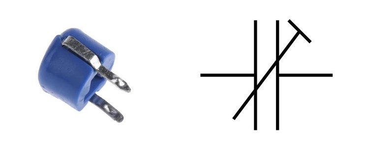
Figure 5: Ceramic Capacitor Symbol
These small capacitors are known for being stable and are frequently used in high-frequency circuits, like those found in radio and communication equipment.
• Mica Capacitors
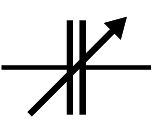
Figure 6: Mica Capacitors
These capacitors are highly reliable and stable, making them a good choice for precise circuits, such as oscillators and radio frequency transmitters.
• Film Capacitors
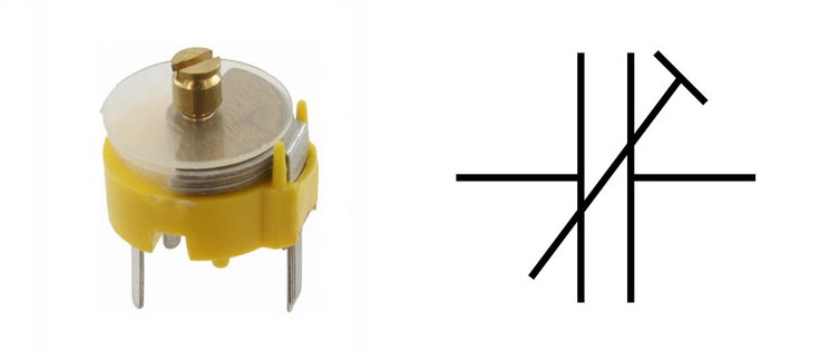
Figure 7: Film Capacitor Symbol
These are widely used in applications that need to handle high voltage or high current, such as power electronics or motor drives. They are durable and last a long time without much change in performance.
Variable Capacitor Symbols
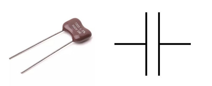
Figure 8: Variable Capacitor Symbol
Variable capacitors allow you to adjust the capacitance, meaning you can change how much charge they store. This makes them useful in circuits where tuning is needed, like in radios. In diagrams, a variable capacitor looks like a non-polarized capacitor but with an arrow through one of the plates to show that its value can be adjusted. These capacitors are often used when you need to fine-tune a circuit, for example, to set a radio to the right frequency.
Specialized Capacitor Symbols
Besides the basic types of capacitors, some are designed for specific uses, and they have their own symbols in circuit diagrams:
• Supercapacitors (Ultracapacitors)
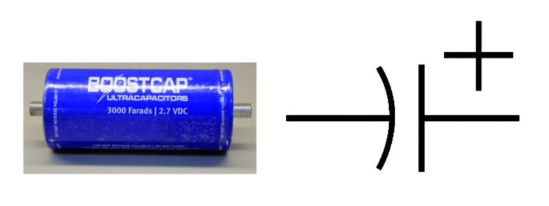
Figure 9: Supercapacitor (Ultracapacitor) Symbol
These capacitors can store and release large amounts of energy quickly. Their symbol is usually made up of two parallel lines connected by a curved line. They are often used in systems that need fast bursts of energy, like electric vehicles.
• Motor Run and Start Capacitors
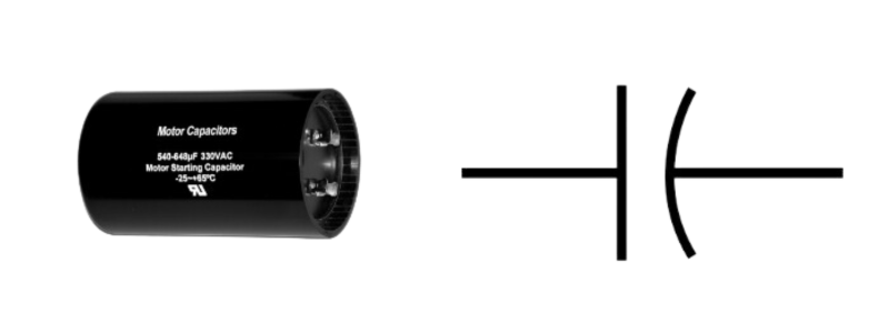
Figure 10: Motor Run and Start Capacitor Symbol
These capacitors are used in electric motors to help them run more smoothly or to start them more easily. Their symbol is similar to a non-polarized capacitor but is sometimes labeled to show that they are meant for motor use.
• Feedthrough Capacitors
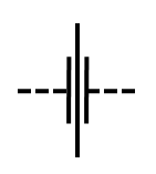
Figure 11: Feedthrough Capacitor Symbol
These are used to reduce electromagnetic interference (EMI) and cut down on noise in circuits. Their symbol often includes a connection to ground, showing their role in filtering unwanted signals.
• Trimmer Capacitors
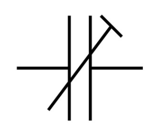
Figure 12: Trimmer Capacitor Symbol
Trimmers are small variable capacitors used for making very fine adjustments in a circuit. Their symbol is similar to that of a variable capacitor but may include extra markings to show their precision role in fine-tuning.
Each type of capacitor has a specific role in circuits, and knowing their symbols helps in understanding how they will function in a given design. Being familiar with these symbols will make it easier to follow circuit diagrams and place components correctly when building or repairing electronics.
Capacitor Symbols on a Multimeter
When using a multimeter to check capacitance, the capacitor symbol is often shown as "F," which stands for Farads, the unit used to measure capacitance. Some multimeters may also use a symbol with two parallel lines, which is the same as the symbol found in circuit diagrams for capacitors.
To measure capacitance with a multimeter, start by setting it to the capacitance mode. This can be labeled with the letter "F" or shown as the two parallel lines symbol. Then, connect the probes of the multimeter to the capacitor's terminals. If you're testing a polarized capacitor (like an electrolytic capacitor), make sure to connect the positive probe to the positive terminal and the negative probe to the negative terminal. Connecting them the wrong way may cause incorrect readings or even damage the capacitor.
After you connect the probes, the multimeter will show the capacitance value. In most cases, this value will be shown in microfarads (µF) because Farads are usually too large a unit for most capacitors. For example, a 10 µF capacitor will show up as 10.000 µF on the multimeter.
Before taking the measurement, it's a good idea to make sure the capacitor is fully discharged. If there is still some voltage left in the capacitor, it could give you a wrong reading or even harm the multimeter. Once you’ve followed these steps, you can safely and accurately measure the capacitance of the capacitor you're testing.
Differences in American and European Capacitor Symbols
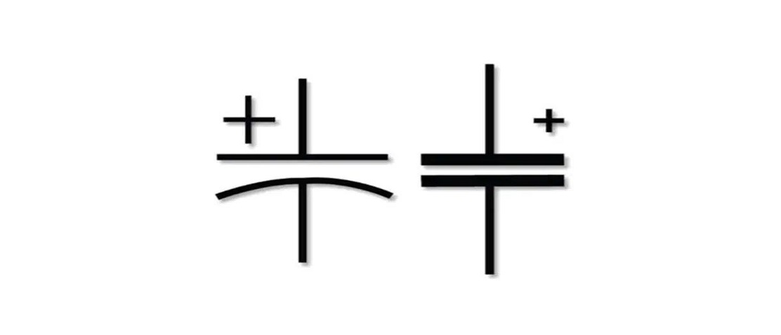
Figure 13: American and European Capacitor Symbols
Capacitor symbols vary slightly between American and European standards, but they serve the same purpose in electrical diagrams.
In the American system, a fixed capacitor is shown with two straight, parallel lines. For polarized capacitors, a "+" sign marks the positive side, or a curved line is used to show the negative side. This makes it clear how the capacitor should be connected, which is especially helpful for certain types of capacitors, like electrolytic ones, that need to be placed in the right direction to work properly.
In the European system, a fixed capacitor is drawn with one straight line and one curved line. The straight line usually represents the positive side, and the curved line shows the negative. Unlike the American system, this symbol can be used for both polarized and non-polarized capacitors, though whether the capacitor is polarized or not often depends on the context of the diagram.
Both systems are easy to understand once you know the difference, but it's helpful to recognize these variations, especially when working with diagrams from different countries. Correctly reading the symbols ensures that capacitors are connected the right way and work as they should.
How to Read Capacitor Symbols in Circuit Diagrams
When you're looking at capacitor symbols in a circuit diagram, there are a few main details you should focus on. Understanding these will help you identify what type of capacitor you need and how it should be placed in the circuit.
Capacitance Value
The capacitance value tells you how much electrical energy the capacitor can hold. It is usually measured in farads (F). However, farads are quite large units, so in most circuits, you'll see much smaller units like microfarads (µF), nanofarads (nF), or picofarads (pF). For example, 1 µF is one-millionth of a farad, and 1 pF is one-trillionth of a farad. These values are written next to the capacitor symbol to show you how much charge it can store.
Tolerance
Tolerance shows how much the actual capacitance of the capacitor might differ from the value printed on it. This is usually given as a percentage. For example, if a capacitor has a tolerance of ±10%, it means the capacitance can be 10% higher or lower than the value shown. This variation may not matter much in some circuits, but in more sensitive ones, it can affect how the circuit works.
Voltage Rating
The voltage rating of a capacitor tells you the highest voltage the capacitor can safely handle. If the voltage in the circuit goes higher than this rating, the capacitor can be damaged, or worse, it could fail. For example, if a capacitor has a voltage rating of 50V, you need to make sure the circuit's voltage stays below 50 volts to avoid problems.
Polarity
Some capacitors, like electrolytic capacitors, are polarized. This means they have a positive terminal (marked with a "+") and a negative terminal (marked with a "-"). It’s very important to place these capacitors in the correct orientation in the circuit. If you connect them the wrong way, they can be damaged or cause the circuit to not work properly.
Conclusion
Capacitors play an important role in many electronic circuits, and their symbols tell us a lot about how they should be used. Whether you’re working with capacitors that need to be connected a certain way or ones that don’t, understanding the symbols helps make sure they are placed correctly. Knowing details like how much charge a capacitor can hold, its voltage limit, and which side is positive or negative, can help you avoid mistakes when building or fixing circuits. By learning how to read these symbols, you'll have a better idea of how to use capacitors in different electronics projects, making your work easier and more successful.
Frequently Asked Questions [FAQ]
1. What is the U symbol in a capacitor?
The "U" symbol, when written as "µ" (the Greek letter mu), stands for microfarads (µF), which is a unit used to measure the capacitance of a capacitor. A microfarad is a very small amount of capacitance.
2. What is the positive symbol on a capacitor?
The positive side of a capacitor is usually marked with a "+" sign. This tells you which terminal (or leg) of the capacitor should be connected to the positive side of the circuit. It is especially important in capacitors that are polarized, like electrolytic capacitors.
3. What is the +- symbol on a capacitor?
The "+-" symbol on a capacitor refers to the range of tolerance. This tells you how much the actual capacitance can vary from the labeled value. For example, if a capacitor is marked 100 µF with a tolerance of ±10%, the actual capacitance could be between 90 µF and 110 µF.
4. How do you read a capacitor?
To read a capacitor, first look at the numbers or letters printed on it. These usually include the capacitance value, given in units like farads (F), microfarads (µF), or picofarads (pF). There may also be a voltage rating, which tells you the maximum voltage it can handle. If it’s a polarized capacitor, it may also have a "+" or "-" symbol to show which way it should be connected in a circuit.
5. How do you check a capacitor symbol"> How do you check a capacitor symbol?
You can recognize a capacitor symbol on a circuit diagram by its shape. A simple capacitor is shown as two parallel lines. For a polarized capacitor, one of the lines might be curved or there may be a "+" sign to indicate the positive side. This helps you know how to place it correctly in a circuit.
About us
ALLELCO LIMITED
Read more
Quick inquiry
Please send an inquiry, we will respond immediately.
220 Ohm Resistor
on September 9th
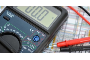
How Does a Digital Multimeter Works?
on September 5th
Popular Posts
-

What is GND in the circuit?
on January 1th 3256
-

RJ-45 Connector Guide: RJ-45 Connector Color Codes, Wiring Schemes, R-J45 Applications, RJ-45 Datasheets
on January 1th 2805
-

Understanding Power Supply Voltages in Electronics VCC, VDD, VEE, VSS, and GND
on November 20th 2615
-

Fiber Connector Types: SC Vs LC And LC Vs MTP
on January 1th 2252
-

Comparison Between DB9 and RS232
on January 1th 1868
-

What Is An LR44 Battery?
Electricity, that ubiquitous force, quietly permeates every aspect of our daily lives, from trivial gadgets to life-threatening medical equipment, it plays a silent role. However, truly grasping this energy, especially how to store and efficiently output it, is no easy task. It is against this background that this article will focus on a type of coin cell battery that may seem insignificant on the...on January 1th 1836
-

Understanding the Fundamentals:Inductance Resistance, andCapacitance
In the intricate dance of electrical engineering, a trio of fundamental elements takes center stage: inductance, resistance, and capacitance. Each bears unique traits that dictate the dynamic rhythms of electronic circuits. Here, we embark on a journey to decipher the complexities of these components, to uncover their distinct roles and practical uses within the vast electrical orchestra. Inductan...on January 1th 1791
-

What Is RF and Why Do We Use It?
Radio Frequency (RF) technology is a key part of modern wireless communication, enabling data transmission over long distances without physical connections. This article delves into the basics of RF, explaining how electromagnetic radiation (EMR) makes RF communication possible. We will explore the principles of EMR, the creation and control of RF signals, and their wide-ranging uses. The article ...on January 1th 1781
-

CR2430 Battery Comprehensive Guide: Specifications, Applications and Comparison to CR2032 Batteries
What is CR2430 battery ?Benefits of CR2430 BatteriesNormCR2430 Battery ApplicationsCR2430 EquivalentCR2430 VS CR2032Battery CR2430 SizeWhat to look for when buying the CR2430 and equivalentsData Sheet PDFFrequently Asked Questions Batteries are the heart of small electronic devices. Among the many types available, coin cells play a crucial role, commonly found in calculators, remote controls, and ...on January 1th 1779
-

Comprehensive guide to hFE in transistors
Transistors are crucial components in modern electronic devices, enabling signal amplification and control. This article delves into the knowledge surrounding hFE, including how to select a transistor's hFE value, how to find hFE, and the gain of different types of transistors. Through our exploration of hFE, we gain a deeper understanding of how transistors work and their role in electronic circu...on November 20th 1767
HOT Part Number
-

EMG4T2R
Rohm Semiconductor
TRANS 2NPN PREBIAS 0.15W EMT5
SN74ALS645AN
Texas Instruments
IC TXRX NON-INVERT 5.5V 20DIP
NCV8720BMT100TBG
onsemi
IC REG LINEAR 1V 350MA 6WDFN
MCP4911T-E/MC
Microchip Technology
IC DAC 10BIT V-OUT 8DFN
B72205S0271K101
EPCOS - TDK Electronics
VARISTOR 430V 400A DISC 5MM
ZTX955STZ
Diodes Incorporated
TRANS PNP 140V 3A E-LINE
XC74WL74AASR
Torex Semiconductor Ltd
IC FF D-TYPE SNGL 1BIT 8MSOPB
LTC2928IG#PBF
Analog Devices Inc.
IC SUPERVISOR 4 CHANNEL 36SSOP
HIP6501ACB
Intersil
POWER CONTROL WITH ACPIINTERFACE
78Q2120C09-64CGT/F
Analog Devices Inc./Maxim Integrated
IC TRANSCEIVER FULL 4/4 64LQFP
SMCJ100A
Littelfuse Inc.
TVS DIODE 100VWM 162VC DO214AB
IRF7322D1
Infineon Technologies
MOSFET P-CH 20V 5.3A 8SO
PS7221A-2A-A
CEL
SSR RELAY SPST-NO 170MA 0-260V
1N5252B
Fairchild Semiconductor
ZENER DIODE, 24V, 5%, 0.5W, UNID
MPCH0740LR36E
KEMET
FIXED IND 360NH 23A 1.42MOHM SMD
GRM0225C1ER60BA03L
Murata Electronics
CAP CER 0.6PF 25V C0G/NP0 01005
RT0402BRE0751KL
YAGEO
RES SMD 51K OHM 0.1% 1/16W 0402
SPH252012H4R7MT
Shenzhen Sunlord Electronics Co., Ltd.
FIXED IND 4.7UH 1.12A 210MOHM SM -
MAX903CPA+
Analog Devices Inc./Maxim Integrated
IC COMPARATOR 1 W/LATCH 8DIP
PIC24FV16KM102-I/SO
Microchip Technology
IC MCU 16BIT 16KB FLASH 28SOIC
NCP81018BMNR2G
onsemi
IC CONTROLLER 3+2 SMD
EPM7256BTI144-7
Altera
IC CPLD 256MC 7.5NS 144TQFP
AP2121AK-2.5TRE1
Diodes Incorporated
IC REG LINEAR 2.5V 200MA SOT23-5
CGA2B2C0G1H331J050BE
TDK Corporation
AUTOMOTIVE GRADE SOFT TERMINATIO
CM430855
Powerex Inc.
SCR MOD DUAL 800V 55A
AD8130ARZ-REEL7
Analog Devices Inc.
IC OPAMP DIFF 1 CIRCUIT 8SOIC
MA27D300GL
Panasonic Electronic Components
DIODE SCHOT 30V 100MA SSSMINI2
ADV7610BBCZ-P-RL
Analog Devices Inc.
IC VIDEO HDMI/RCVR 76CSPBGA
CC2640R2LRHBR
Texas Instruments
SIMPLELINK BLUETOOTH 5.1 LOW ENE
APTD2012LSYCK
Kingbright
LED YELLOW CLEAR 2012 SMD
S-8540D00FN-IMBT2G
ABLIC Inc.
IC REG CTRLR BUCK 8MSOP
MAX4507CAP
Analog Devices Inc./Maxim Integrated
IC OVERVOLTAGE PROTECTION 20SSOP
G6DS-1A-H DC12
Omron Electronics Inc-EMC Div
RELAY GEN PURPOSE SPST 5A 12V
EP2S90F1020C3N
Altera
IC FPGA 758 I/O 1020FBGA
TZMB33-GS08
Vishay General Semiconductor - Diodes Division
DIODE ZENER 33V 500MW SOD80
UWT1V330MCL1GB
Nichicon
CAP ALUM 33UF 20% 35V SMD -
LTM2892CY-S#PBF
Analog Devices Inc.
DGTL ISOL 3500VRMS 6CH SPI 24BGA
EP2AGX190EF29I5G
Intel
IC FPGA 372 I/O 780FBGA
PTH03020WAST
Texas Instruments
DC DC CONVERTER 0.8-2.5V
2N5245
Fairchild Semiconductor
SMALL SIGNAL FET
74F244SCX
onsemi
IC BUF NON-INVERT 5.5V 20SOIC
2FA1-NDRP-PCB-6
Amphenol RF
FAKRA GEN 2 PCB THROUGH HOLE RIG
LT1490AIDD#TRPBF
Analog Devices Inc.
IC OPAMP GP 2 CIRCUIT 8DFN
SZMMSZ4691T1G
onsemi
DIODE ZENER 6.2V 500MW SOD123
EP4S100G5F45I1
Intel
IC FPGA 781 I/O 1932FBGA
BCM33843MKFSBG
Broadcom Limited
CABLE MODEM
CC1210KKX7R8BB106
YAGEO
CAP CER 10UF 25V X7R 1210
AQY225R1SX
Panasonic Electric Works
SSR RELAY SPST-NO 350MA 0-80V
MM74HC125N
onsemi
IC BUFFER NON-INVERT 6V 14DIP
DM7410N
Texas Instruments
NAND GATE, 3-INPUT, TTL, PDIP14
PEF2055NV2.1
Infineon Technologies
PCM INTERFACE CONTROLLER
MMSZ5248B
Diotec Semiconductor
ZENER SOD-123 18V 0.5W 5%
1N3880
GeneSiC Semiconductor
DIODE GEN PURP 100V 6A DO4
GRM0337U1H4R4CD01D
Murata Electronics
CAP CER 4.4PF 50V U2J 0201