Various Types of Capacitors In Electronic Technology
In an era where electronic technology surges forward with breathtaking speed, capacitors stand as fundamental components in this dynamic landscape. Each type, from ceramic to polyester, polystyrene to polypropylene, boasts unique characteristics tailored for distinct environments. This article delves into a kaleidoscope of capacitors. We traverse the intricate world of monolithic ceramic capacitors, paper, and metalized paper types, journey through the realms of aluminum and tantalum electrolytic variants, and explore the nuances of mica, mica trimmer, and their ceramic and film counterparts. Then, there are air variable and film variable capacitors.Catalog

Ceramic Capacitors (CC)
Basic Structure and Working Principle
Employing high-temperature sintering technology, ceramic capacitors are crafted using ceramic materials as the dielectric. These capacitors are typically coated with a metal film, often silver or copper-plated silver, to create electrodes. The essence of this technology is its sophisticated thin film technique, pivotal for ensuring electrode uniformity and the capacitor's adeptness in handling high-frequency signals. A capacitor's primary function, storing charge between its two electrodes, is quantified in farads (F).
Dielectric Classification and Characteristics
The first type of dielectric, Class 1, encompasses varieties like NPO (negative polarity temperature compensation) and CCG (general temperature compensation). These capacitors boast a low dielectric constant and temperature coefficient. For instance, NPO capacitors maintain a steady capacitance value regardless of temperature fluctuations, making them exceptionally suitable for high-stability applications. Key strengths include their minimal temperature coefficient (±30ppm/°C), superior high-frequency performance, remarkably low losses (high Q value), and high voltage endurance. However, their capacitance typically does not exceed 1000pF.
Figure 1: Ceramic Capacitors (CC)
Conversely, Class 2 and Class 3 dielectrics, including X7R, 2X1, Y5V, and 2F4, offer higher dielectric constants, thereby providing larger capacitance values, possibly reaching 0.47μF or more. Yet, this increased capacity comes at the cost of reduced temperature stability and heightened losses. The X7R capacitor, for example, displays a capacitance value fluctuation within ±15% across a temperature spectrum of -55°C to +125°C. In stark contrast, the Y5V's capacitance value can vary beyond ±82% within the -30°C to +85°C range. These capacitors find their niche in applications where temperature stability is not paramount, such as in power supply filtering, signal coupling, and bypassing.
Application and Selection Considerations
In choosing a ceramic capacitor, a myriad of factors come into play. Beyond the basic capacitance value and voltage rating, considerations extend to temperature characteristics, frequency response, and environmental stability. High-frequency circuits, for instance, benefit from Type 1 capacitors due to their low loss and excellent high-frequency traits. Conversely, in power supply filtering or signal coupling scenarios, Type II or III capacitors may be more apt, given their less stringent temperature stability demands.
Additionally, the capacitor's physical dimensions are critical, influencing its integration into the circuit board and its thermal dynamics. Smaller capacitors economize PCB (printed circuit board) space but might compromise on capacitance and voltage resistance. Balancing space limitations with electrical performance is thus a crucial aspect of design.
Technical Challenges and Innovation Directions
As electronic devices trend towards miniaturization, the demand for smaller yet high-capacity capacitors escalates. To meet this demand, researchers and manufacturers are exploring new dielectric materials and manufacturing techniques to amplify capacitor capacity density.
Moreover, enhancing temperature stability, especially for Type II and III capacitors, remains an ongoing challenge. Innovations in materials and dielectric formulations are under exploration to bolster these capacitors' performance across various temperatures.
Addressing the aging effect, where capacitors experience a gradual reduction in capacity over time, is another focus area. New dielectric materials and improved capacitor designs are being investigated to mitigate this phenomenon.
As a basic component of electronic products, the performance of ceramic capacitors plays an important role in the stability and efficiency of the entire circuit. Understanding the different characteristics and application environments of different capacitor types allows for more informed decisions in circuit design. With the continuous advancement of technology and material innovation, the functions and applications of ceramic capacitors will surely expand to support a range of high-tech applications.
Polyester Capacitors (CL)
Material and Structural Properties
At the heart of polyester capacitors lies the polyester film, a dielectric material celebrated for its exceptional electrical insulation and mechanical strength. Resilient in the face of heat and chemicals, this film enables the capacitors to thrive in high temperatures and hostile environments. A key feature: its electrically insulating properties imbue the capacitors with high dielectric strength. This means they are adept at handling high voltage.
In-depth Understanding of Temperature Characteristics
A distinctive aspect of polyester capacitors is their positive temperature coefficient. As the temperature climbs, so does their capacitance. In the dance of fluctuating temperatures, this trait grants them stability within a certain range. A stark contrast to the negative coefficient found in other types, like ceramic capacitors.
Detailed Explanation of Pressure and Capacity Markings
A unique coding system is the language for expressing a polyester capacitor's voltage and capacity. Voltage, for instance, is conveyed through a blend of letters and numbers; "2A" signifies 100V, while "2C" means 160V. This system is a beacon for designers, guiding them swiftly to the capacitor's traits. Capacities are measured in picofarads (pF) or microfarads (μF), with a numeric code, like "224", indicating 0.22μF. The last letter, such as "J," reveals capacity tolerance—important to circuit accuracy.
Detailed Application Fields
Polyester capacitors, boasting high temperature and voltage resistance, moisture resistance, and economical efficiency, are stalwarts in various electronic equipment. Predominantly, they shine in low and medium-frequency circuits as bypass capacitors, filtering noise, and stabilizing voltage. Notable models, including CL11 and CL21, play pivotal roles in power circuits, signal processing, and electronic filters.
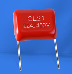
Figure 2: Polyester Capacitors (CL)
Technical Challenges and Future Development
Despite their versatility, polyester capacitors face challenges. Extreme temperatures can unsettle the stability of polyester materials, impacting performance. Future research aims at crafting polyester with enhanced temperature stability, widening their high-temperature application scope.
In the realm of ever-shrinking electronic equipment, the quest for smaller, higher-capacity polyester capacitors intensifies. Innovations in thinner polyester films and more efficient electrode materials are underway, promising a leap in capacitor capacity density.
polyester capacitors, with their unique positive temperature coefficient and robust resistance qualities, stand as cornerstones in electronic circuit design. Understanding their marking system and performance nuances empowers designers to make precise choices for specific applications. As materials science and manufacturing technology evolves, polyester capacitors are poised to scale new heights in performance and application diversity.
Polystyrene Capacitors (CB)
Differences and Optimization Between Foil and Metallized Capacitors
Foil Capacitor: This capacitor type features layers of metal foil as electrodes, nestled between polystyrene films. Its hallmark? Exceptionally low dielectric losses and high insulation resistance, imbuing foil capacitors with outstanding electrical properties, such as low losses and high stability. The flip side? Their size - notably large. And, the polystyrene's poor heat resistance bars them from high-temperature environments. The improvement path? A quest for thinner, yet efficient materials to slash size and enhance temperature stability.
Metalized Capacitor: Here, a slender metal film, vapor-deposited on a polystyrene film, serves as the electrode. The result? A more compact design, augmented with superior moisture resistance and self-healing abilities. What does self-healing entail? In a voltage breakdown scenario, the metallization layer can vaporize in parts, saving the capacitor from total ruin. But, there's a catch: these capacitors lag in insulation resistance and underperform in high-frequency scenarios compared to foil capacitors. The innovation direction? Delving into more refined metallization processes and film structures to beef up high-frequency traits.
Expansion of Application Fields
Polystyrene capacitors, boasting high accuracy and stability, have carved a niche in precision instruments, high-precision DAC circuits, automotive electronics (like radios), and industrial proximity switches. Evolution in technology ushered them into communications, high-end audio, and medical instruments.
Technical Challenges and Innovation Directions
Improved Temperature Stability: The Achilles' heel? The temperature sensitivity of polystyrene materials. The game plan? Either tweak the material formulation or hybridize it with materials stable at high temperatures, aiming for better temperature stability and reliability.
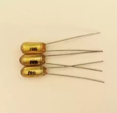
Figure 3: Polystyrene capacitor (CB)
Miniaturization and Integration: The trend in electronic devices leans towards the miniature. This spurs a demand for smaller yet high-performing capacitors. The solution? Refining the design and experimenting with novel materials to shrink the capacitors while preserving their electrical prowess.
Polystyrene capacitors, with their unique electrical properties, are pivotal in applications demanding precision and stability. Foil capacitors shine in high-precision, low-loss applications, while metalized variants, thanks to miniaturization and self-healing properties, cater to a broader spectrum. The road ahead? Enhancing temperature tolerance, downsizing, and amplifying voltage and frequency handling to meet the escalating demands of electronic equipment. As new materials and advanced manufacturing techniques emerge, we anticipate an expanded performance spectrum and application range for polystyrene capacitors, heralding more robust and efficient solutions for diverse high-tech applications.
Polypropylene Capacitors (CBB)
The Intricacies of Material Properties and Capacitor Construction
Boasting non-polar polypropylene film, polypropylene capacitors showcase exceptional electrical characteristics. These include minimal dielectric loss, heightened insulation resistance, and remarkable capacitance stability. Intriguingly, the non-polar nature ensures minimal fluctuation in capacitance in response to temperature variations, due to a negative temperature coefficient. This feature is pivotal, as it guarantees consistent performance, even amidst significant temperature shifts.
A Contrast: Sealed Versus Unsealed Capacitors
Unsealed type: Predominantly encapsulated in colored resin paint, these capacitors are not only lighter but also more cost-effective. But, here's the catch - their durability falters in harsh conditions like high humidity or corrosive environments.
Sealed type: Encased in either metal or plastic shells, these capacitors benefit from enhanced physical strength and environmental resilience. Their robust construction renders them ideal for industrial use and extreme operational settings.
Diving Deeper: Application Areas
In the realm of medium and high-frequency circuits, polypropylene capacitors serve crucial roles in filtering, resonance, and cross-line tasks. Their low losses and stability are particularly valuable in applications demanding meticulous frequency regulation and signal processing.
Motor Starting Capacitors: These capacitors are used in motor starting especially where high capacitance and withstand voltage are required. They ensure sufficient starting torque and promote smooth motor operation.

Figure 4: Polypropylene Capacitors (CBB)
Foil Versus Metallized Capacitors: Distinctive Features
Foil polypropylene capacitors (CBB10, CBB11, CBB60, CBB61): Employing metal foil electrodes, they promise high capacity stability and precision. However, their larger size is a notable drawback.
Metalized polypropylene capacitors (CBB20, CBB21, CBB401): These utilize an evaporated metal layer on the film to form electrodes, enhancing compactness and self-healing capabilities. it allows the metallization layer to evaporate in damaged areas during voltage breakdowns, averting complete failure. Despite slightly lower insulation resistance than foil capacitors, they excel in volumetric efficiency and cost-effectiveness.
Their Role in High-Frequency and High-Power Circuits
In high-frequency, high-power settings like power transmission and wireless communication, CBB capacitors are favored for their efficient energy conversion and signal processing capabilities. Their low dielectric loss and effective frequency response make them indispensable, especially in handling high-power signals.
Looking Ahead: Technical Challenges and Future Prospects
Temperature resistance improvements: Despite their numerous strengths, enhancing temperature resistance remains a challenge. Research is underway to find new polypropylene materials that can endure higher temperatures, expanding their application scope.
Miniaturization and Integration Technology: As electronic devices shrink, the demand for smaller yet powerful polypropylene capacitors grows. Advancements in thin-film technologies and integrated designs are being explored to reduce physical size while preserving or augmenting electrical performance.
Due to their excellent electrical properties and low losses, polypropylene capacitors can be flexibly adapted to different requirements in medium/high-frequency circuits and motor starting applications, whether foil or metalized. Going forward, advances in materials science and manufacturing are likely to lead to further optimizations in size, performance, and environmental adaptability to meet the changing demands for efficient, compact capacitors in modern electronic devices.
Monolithic Ceramic Capacitors (MLCC)
Materials and Manufacturing Processes
At the heart of monolithic ceramic capacitors are multilayer structures, crafted meticulously from barium titanate-based ceramic materials. This material undergoes a sintering process at soaring temperatures, creating remarkably thin dielectric layers. These layers, through the intricate art of lamination technology, form the core of MLCC's design. This approach significantly elevates the capacitance density per unit volume, allowing these compact MLCCs to boast larger capacitance values in remarkably small spaces.
Electrical Performance and Characteristics
MLCCs, known for their solid-state construction and meticulous manufacturing, are paragons of high reliability. These capacitors thrive in diverse environments, thanks to their remarkable resistance to high temperatures and moisture. Their capacitance range spans from 1pF to 1μF, catering to various circuit designs. A critical feature, low leakage current, underscores their role in energy efficiency and circuit stability. Yet, their Achilles' heel lies in their low operating voltage, typically under 100V, restricting their use in high-voltage scenarios.
Application Areas
In the realm of modern electronic devices, They are pivotal in resonance and filtering within signal processing and power management circuits, excising noise, and fortifying voltages. Acting as bypass capacitors in analog and digital circuits, they ensure a stable supply voltage or, as coupling capacitors, they bridge circuits without mingling their DC components.
Model and Frequency Characteristics
MLCC models, such as CT4, CT42, CC4, and CC42, are tailored for distinct frequency characteristics, meeting diverse application needs from low to high frequencies.
Figure 5: Monolithic Ceramic Capacitors (MLCC)
Models like CT4 and CT42 are optimal for scenarios demanding stable capacitance, predominantly in low-frequency applications. Conversely, models such as CC4 and CC42 excel in high-speed signal processing and communications, navigating the realm of high frequencies with ease.
Technical Challenges and Future Development Directions
The pursuit of stronger voltage resistance is very helpful for MLCC to enter the field of high-voltage applications. Innovations in ceramic materials and production techniques are at the forefront of this effort. Equally important is increasing capacitance density. As electronic devices around the world trend toward greater miniaturization, demand for larger-capacity MLCCs continues to grow. Achieving these goals is becoming feasible through advances in materials and lamination technology.
Although multilayer ceramic capacitors are small, they have high capacity, reliability, and stability, and are components that cannot be ignored in electronic equipment. From LCD watches and micro-instruments to smartphones and computers, their role in capacitance is irreplaceable. Looking to the future, the combination of new materials and advanced manufacturing technologies is expected to bring more possibilities to MLCCs. In particular, progress in improving capacitance density and enhancing voltage resistance is expected to enable MLCCs to be used in a wider range of electronic products, significantly increasing their application scope.
Paper Capacitors (CZ)
Construction and Material Properties
Utilizing special capacitor paper as the dielectric, paper capacitors are treated to enhance insulation and stability. Aluminum or lead foil, chosen for their superior electrical conductivity and ease of processing, serve as electrodes. This unique construction empowers these capacitors to handle high voltages, offering a wide capacitance spectrum, ranging from 100pF to 100μF.
Advantages and Application Scope
These capacitors boast a broad operating voltage range, withstanding up to 6.3kV – ideal for high voltage scenarios. They also excel in large capacity, providing 100pF to 100μF, catering to situations demanding substantial capacitance. Predominantly, they find their niche in power systems, motor starting circuits, and high-voltage testing apparatus.
Shortcomings and Improvement Directions
In comparison to their counterparts, paper capacitors are bulkier for the same capacitance value. Their capacity accuracy and stability are somewhat limited, hindering precision electronic device applications. Furthermore, their high loss characteristic leads to energy inefficiency. Current research focuses on innovating insulating materials and compact designs to address these issues.
Figure 6: Paper Capacitors (CZ)
Inductive and Non-inductive Capacitors
Inductive capacitors, consisting of multiple strip coils, suit low-frequency applications due to their large inductance. In contrast, non-inductive capacitors, through a clever design, stagger electrode foils on the paper tape. This structure, involving a cylindrical iron core and welded leads, minimizes inductance, rendering these capacitors ideal for high-frequency uses in electronic equipment demanding low inductance.
Technical Improvements and Future Development
As electronic technology progresses, paper capacitors are pivoting from traditional to modern electronic device applications. Innovations include researching high-performance dielectric materials to diminish volume and enhance capacity accuracy and stability. Additionally, structural optimizations are underway to reduce losses and bolster overall performance. These include the implementation of thinner dielectric layers and the use of more efficient electrode materials.
Common Models and Application Areas
The CZ series, encompassing models like CZ11, CZ30, CZ31, CZ32, CZ40, and CZ80, are prevalent in power systems, motor starting mechanisms, and high-voltage power supplies, among other large-capacity capacitor applications. Despite their size, precision, and stability constraints, ongoing advancements in materials and design are poised to broaden their applicability in modern electronics. With these emerging technologies, paper capacitors are anticipated to unlock greater potential, particularly in specialized fields, marking a significant evolution in their journey.
Metallized Paper Capacitors (CJ)
Manufacturing Process and Material Properties
Utilizing vacuum evaporation technology, metalized paper capacitors epitomize precision; a thin metal film, typically aluminum or zinc, is evaporated onto capacitor paper, itself coated with a special paint film, serving as an electrode. This intricate manufacturing process fosters a capacitor characterized by a uniform, dense electrode layer, thus significantly enhancing the capacitor's overall performance.
Volume and Capacity Advantages
Metalized paper capacitors, when compared with their traditional counterparts, are remarkably smaller yet boast a larger capacity. This stems from their thinner electrode layers, which, despite their slimness, maintain adequate conductivity - a feature enabling higher capacitance density.
Self-healing Characteristics
Intriguingly, when a metalized paper capacitor encounters a breakdown, its unique self-healing properties spring into action. The metal film at the breakdown site evaporates under high temperatures, leaving behind an insulating hole. This ingenious design mitigates short circuit risks, markedly elevating the capacitor's reliability and lifespan - a stark contrast to traditional paper capacitors, which typically succumb to short circuits post-breakdown.
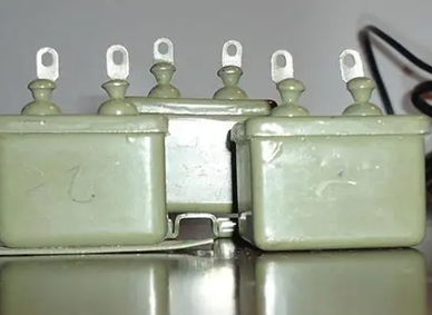
Figure 7: Metallized Paper Capacitors (CJ)
Application Areas
Metalized paper capacitors, distinguished by their miniaturization, high capacity, and robust self-healing properties, are particularly well-suited for applications demanding stable reliability. Power supply circuits, motor starting circuits, and lighting circuits are among their common uses, as are scenarios requiring high withstand voltage and current.
Common Models and Performance
Prominent models like the CJ10 and CJ11 series, among others, come in various voltage levels and capacities, tailored to diverse application needs.
Technical Challenges and Future Development
The journey towards further miniaturization aligns with the growing trend for more compact electronic equipment, driving demand for smaller yet high-performance capacitors. Future developments may pivot on size reduction while either maintaining or enhancing performance. Concurrently, material innovation is a critical area, exploring new metal evaporation materials and paper-based dielectrics to enhance temperature resistance and electrical performance. Metalized paper capacitors, through their unique manufacturing process and self-healing properties, offer a reliable, high-performance capacitive solution in electronic devices. Their advantages in size, capacity, and stability have garnered widespread popularity across various applications. Looking forward, with advancements in materials and manufacturing technology, we anticipate a broadening in the performance and application scope of these capacitors. Particularly, strides in improving temperature resistance, reducing size, and augmenting capacitance density are set to empower metalized paper capacitors with an even greater role in demanding electronic equipment and high-end applications. Through continuous technological optimization and innovation, these capacitors are poised to maintain their crucial role in modern electronic and power applications.
Aluminum Electrolytic Capacitors (CD)
Construction and Material Properties
Aluminum electrolytic capacitors, a marvel of engineering, consist of two aluminum foil layers. One layer, coated with a thin aluminum oxide film, functions as the positive electrode, while the other acts as the negative electrode. The positive electrode interfaces with a conductive backing paper, drenched in an electrolyte solution, typically paper or plastic film. The thickness and consistency of the oxide film determine the voltage resistance and leakage current characteristics of the capacitor.
Appearance Packaging and Features
Typically, aluminum electrolytic capacitors are encased in two styles: vertical and tubular. Their outer shells are often sheathed in a blue or black plastic cover, offering mechanical protection and insulation. The choice of packaging is influenced primarily by board space and mounting requirements.
Electrical Performance
These capacitors boast a wide capacity range, spanning from 1μF to 10000μF, accommodating a plethora of circuit designs. They also offer a broad rated operating voltage range, from 6.3V to 450V, catering to diverse voltage needs. However, they are not without drawbacks. Medium losses, for instance, lead to lower energy efficiency. The capacity error can be substantial, with allowable deviations of +100%, and -20%, a consideration in precision circuits. Additionally, their poor high-temperature resistance limits usage in heat-intensive environments. Furthermore, long-term storage stability is a concern, as it can lead to performance degradation over time.
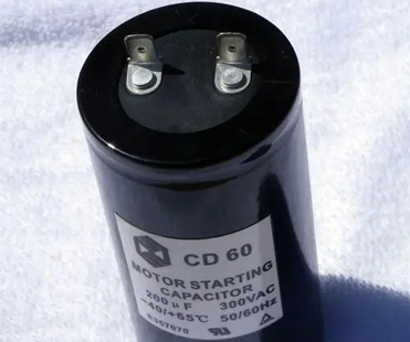
Figure 8: Aluminum Electrolytic Capacitors (CD)
Application Areas and Selection Considerations
Predominantly utilized in DC power circuits or medium and low-frequency circuits, aluminum electrolytic capacitors find their niche in filtering, decoupling, signal coupling, time constant setting, and DC isolation. Selection of these capacitors requires careful consideration of not just capacity and withstand voltage, but also size, loss rate, temperature range, and long-term stability. Large-capacity capacitors, while advantageous in energy storage, also bring increased costs, larger sizes, and extended charging times, necessitating a balance of these factors according to the specific application.
Technical Challenges and Future Development
The pursuit of innovation in materials and manufacturing processes is to improve temperature resistance and reduce volume, and researchers are studying new electrolyte materials and working to improve the quality of oxide films. Enhancing long-term stability is another focus, seeking to improve performance stability after long-term storage through advances in electrolyte formulation and encapsulation technology. In addition, efforts are underway to improve energy density and efficiency, researching more efficient capacitor designs that provide higher energy density and reduce losses.
Aluminum electrolytic capacitors have a wide capacity range and high-rated operating voltage and are an important component in many DC power supplies and medium and low-frequency circuit designs. Despite challenges with losses, capacity errors, and high-temperature resistance, continued technological innovation promises significant progress. In the future, these capacitors are expected to achieve breakthroughs in miniaturization, long-term stability, and high efficiency. These improvements will enable them to play a more important role in a wider range of applications, especially in modern electronic devices that require high capacity and reliability. As new materials and cutting-edge manufacturing technologies become available, aluminum electrolytic capacitors will continue to secure their important position as key capacitor type in electronics and power applications.
Tantalum Electrolytic Capacitors (CA)
Construction and Material Properties
Tantalum electrolytic capacitors manifest in two distinct forms: the foil type and the tantalum powder sintered type.
The foil-type tantalum electrolytic capacitor, utilizing tantalum oxide as the dielectric, boasts an internal core structure. Its negative electrode, leveraging liquid electrolyte, endows the capacitor with high capacity and exemplary electrical performance. Predominant models include the CA30, CA31, CA35, and CAk35 series.
Conversely, the tantalum powder sintered cathode capacitor emerges from sintering ultra-fine tantalum powder blocks. This process engenders a higher surface area, culminating in an augmented capacitance value. They're versatile and encapsulated in various packages to accommodate diverse application demands. Popular models span the CA41, CA42, CA42H, CA49, and CA70 (non-polar) series.
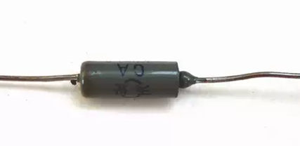
Figure 9: Tantalum electrolytic capacitor (CA)
Electrical Properties and Advantages
The tantalum electrolytic capacitors' unique structure permits small volume yet large capacity. They operate across a wide temperature range: from -50℃ to +100℃, catering to myriad environmental conditions. Their longevity and high insulation resistance ensure stable performance, particularly in high-frequency applications. Attributes like small leakage current and favorable impedance frequency characteristics render them ideal for precision electronic equipment. Furthermore, their stable chemical properties, courtesy of the tantalum oxide film dielectric, guarantee consistent performance even in harsh acid or alkaline environments. Notably, when juxtaposed with aluminum electrolytic capacitors, they exhibit minor losses and superior temperature stability, thereby enhancing reliability in fluctuating temperature scenarios.
Technical Challenges and Future Development
The quest for increased capacity density persists, especially with electronic equipment trending towards miniaturization. There's an ongoing endeavor to augment their temperature resistance, despite the already broad range, to ensure performance under extreme conditions. Cost reduction remains pivotal, as the high expense of tantalum materials is a barrier to broader application.
In the realm of electronic equipment, tantalum electrolytic capacitors are esteemed for their compact size, vast capacity, enduring lifespan, and unwavering reliability. They shine in high-frequency applications and wherever temperature stability is paramount. Looking forward, technological advancements are anticipated to further elevate their capacity density, temperature endurance, and cost efficiency. This progression promises to cement their integral role in more sophisticated, high-end electronic applications.
In summary, tantalum electrolytic capacitors stand at the forefront of electronic component innovation. Their journey, marked by continuous improvement and adaptation, reflects the dynamic nature of technology itself. As they evolve, so too does their potential to revolutionize the electronic world, making them a subject of fascination and importance in the ever-changing landscape of technological advancements.
Mica Capacitors
Material and Construction Characteristics
Mica capacitors, employing either natural or synthetic mica as the dielectric, are renowned for their superb electrical properties and chemical stability. The mica sheet is adorned with a metal film, typically silver, acting as an electrode. This intricate design not only enhances electrical conductivity but also upholds the medium's integrity and stability, a delicate balance.
Packaging and Assembly
Metalized mica sheets, meticulously stacked to meet the required capacity, are encased in bakelite, ceramic, or plastic shells. Such packaging is multifunctional: it protects the capacitor's internal structure and imparts mechanical strength and insulation, a dual purpose.
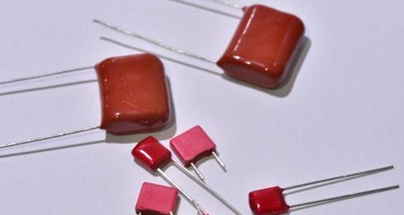
Figure 10: Mica Capacitors
Electrical Properties and Advantages
The mica capacitor's main advantages include:
Extremely high stability: Ensuring long-term reliability, a cornerstone.
Low distributed inductance and low losses: Ideal for high-frequency applications.
High precision and large insulation resistance: Tailored for precision electronic equipment.
Excellent temperature characteristics: Spanning a wide range, from 50V to 7kV.
Application Areas
Mica capacitors find their niche in:
High-frequency circuits: Signal coupling, bypass, tuning, and more.
Electronics, power, and communication equipment: Offering stable capacitive solutions.
Harsh environments: Aerospace, aviation, navigation, rockets, satellites, military electronics.
High-precision instruments: play a key role in applications such as oil exploration.
Models and Designs
Typical models like the CY, CYZ, and CYRX series cater to diverse needs, providing a spectrum of capacities and voltage levels tailored for various applications.
Technical Challenges and Future Development
Innovation in materials is anticipated to elevate the performance and reliability of mica capacitors. Miniaturization and integration are key to aligning with modern electronic trends. Mica capacitors, integral in high-frequency circuits and extreme environments, stand out for their stability, low loss, high precision, and exceptional temperature characteristics. Their reliability and stability have carved a niche for them in fields such as electronics, communications, aerospace, and aviation. Looking ahead, the evolution of materials and manufacturing technologies is likely to spur significant strides in miniaturization, performance enhancement, and cost efficiency. This will enable mica capacitors to play a pivotal role in an even broader spectrum of high-end electronic applications. As they continue to evolve through technological innovation, mica capacitors are set to solidify their status as high-performance, high-reliability capacitor types in the realms of electronic and power applications.
Mica Trimmer Capacitor (CY)
Structure and Working Principle
In the heart of the mica trimmer capacitor lies a duo: a steadfastly fixed piece and a dynamic movable piece. The fixed plate, typically a metal surface, embraces a mica dielectric layer, ensuring stable capacitive characteristics. Contrastingly, the movable piece - crafted from pliant copper or aluminum - dances along the fixed piece, sliding or rotating with grace.
A mere twist of a screw or a turn of a knob on the movable piece unfolds a dance of precision: it alters the relative position to the fixed piece, fine-tuning the capacitance value with astonishing accuracy. As the gap between the two parts ebbs and flows, so does the capacitance - a delicate balance of distance and value.
Types and Characteristics
The single trimmer capacitor: a solitary adjustable piece, a simple yet effective tool for basic trimming tasks.
Enter the dual trimmer: with its twin adjustable blades, it offers a subtler, more nuanced adjustment capability, and a broader scope of flexibility.
Their crowning glory? The ability to tweak capacitance values with laser-like precision is ideal for circuits thirsting for meticulous adjustments.
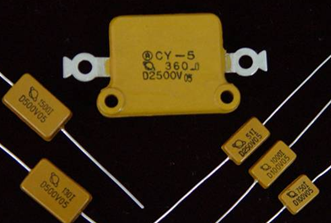
Figure 11: Mica Trimmer Capacitor (CY)
Application Areas
Mica trimmer capacitors, the unsung heroes in:
Transistor radios: tuning into the whispers of frequencies.
Electronic Instruments: the meticulous calibrators, guardians of accuracy in electronic measuring gear.
Other electronic wonders: a cornerstone in devices craving precise capacitance control - from the realms of wireless communications to the intricacies of frequency regulators and signal processors.
Technical Challenges and Future Development
Miniaturization and integration march forward, hand in hand, as the world of electronics shrinks yet grows in complexity. This demands trimmer capacitors that not only fit into tighter spaces but also boast higher precision.
Material innovation: a quest for new dielectric and metallic materials, aiming to enhance the stability and longevity of capacitors.
Expanding horizons: developing trimmer capacitors that offer a wider range of capacitance adjustments.
Mica trimmer capacitors stand at the forefront of precision tuning in various electronic devices and instruments. Poised for breakthroughs in miniaturization, precision enhancement, and material performance, they aim to meet the ever-evolving demands for high-performance, reliable capacitors.
Ceramic Trimmer Capacitors (CC)
Structure and Working Principle
Ceramic trimmer capacitors, a marvel in their own right, employ ceramic as the dielectric, a testament to its superb properties and stability. The moving and fixed parts of the capacitor, each adorned with a semi-circular silver electrode layer, engage in a delicate dance. By rotating the rotor, the overlap of these silver layers shifts, enabling a precise adjustment of the capacitance value.
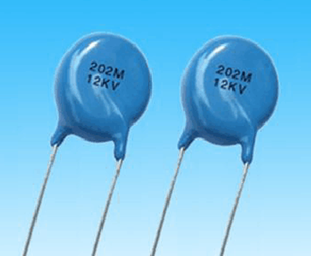
Figure 12: Ceramic Trimmer Capacitors (CC)
Design Features
A compact marvel: Their small stature makes them perfect for environments where space is at a premium.
Tune with ease: A simple rotation allows for repeated, fine-tuning - ideal for scenarios demanding constant adjustment.
Application Areas
Transistor radios: masters of reception frequency and signal strength adjustment.
Electronic instruments: precision tools in measurement and signal processing devices, fine-tuning circuit parameters with finesse.
Electronic equipment: particularly favored in devices where size and flexibility in adjustment are crucial.
Technical Challenges and Future Development
Material optimization: A quest for superior ceramic materials to boost stability and endurance.
Accuracy enhancement: Crafting more refined adjustment mechanisms to satisfy high-precision application demands.
Integration and miniaturization: As electronic devices veer towards being smaller yet more integrated, the push for miniaturized ceramic trimmer capacitors grows. R&D teams are challenged to shrink capacitor sizes while elevating their performance.
Ceramic trimmer capacitors, indispensable in a plethora of electronic devices, are celebrated for their compact size and the simplicity of repeated adjustments. They find extensive use in transistor radios, electronic instruments, and other electronic equipment, particularly where space constraints exist and frequent capacitance adjustments are necessary.
Thin Film Trimmer Capacitors
Construction and Material Properties
Employing organic plastic films as the dielectric, thin film trimmer capacitors are noted for their excellent dielectric properties and stability. The architecture of these capacitors, characterized by a moving and a stationary part, is ingeniously simple. The moving part's adjustability is achieved through precision screws, a testament to thoughtful engineering.
Adjustment Mechanism
The core of the adjustment lies in the screw on the moving piece. Twisting it, the moving piece artfully rotates, altering its position relative to the stationary part. This intricacy enables users to meticulously adjust the capacitance, fine-tuning the circuit's capacitance value with remarkable precision.
Types and Characteristics
The dual and quad trim types present a spectrum of adjustment flexibility. The dual trim is a stalwart for basic applications, whereas the quad trim excels in offering more nuanced adjustments.
Sealed Double or Quad Variable Capacitors, distinguishable by their membrane trimmers, are conveniently user-accessible and mounted atop the case.

Figure 13: Thin Film Trimmer Capacitors
Advantages and Applications
Their diminutive size and featherlight weight render thin film trimmers ideal for applications where volume and weight are at a premium. The capacity for repeated adjustments stands out, affording users effortless fine-tuning of capacitance values as needed.
Application Scenarios
These capacitors are ubiquitous in transistor radios and electronic instruments and are important because of their flexibility and compact design. In these cases, they excel at optimizing space and enhancing functionality.
Technical Challenges and Future Development
In the realm of materials innovation, the quest continues for new thin film substances to bolster capacitor stability and endurance, especially under extreme conditions. The pursuit of improved accuracy and reliability is relentless, aiming to craft capacitors that meet the demands of high-end electronics. As electronic devices shrink, the call for more miniature, integrated thin-film circuits grows louder. The burgeoning demand for capacitors propels research towards smaller yet equally or more efficient designs.
The key strengths of thin film trimmer capacitors - small size, lightness, and adjustable capacity - make them vital in electronic equipment. They enhance space utilization and functionality, and with ongoing advances in materials and miniaturization, their significance is set to soar.
Air Variable Capacitor (CB)
Structure and Working Principle
At its core, the air variable capacitor is elegantly simple yet fascinatingly complex. Utilizing air as the dielectric medium, it comprises two distinct sets of metal sheets: the stator, immovable, and the rotor, ever-dynamic. The dance between the rotor and the stator, governed by the rotation of the rotor, alters the overlap area between them. This dance intricately adjusts the capacitor's capacitance value, which peaks when the rotor fully engages with the stator and dips to its nadir when completely retracted.
Types and Characteristics
In terms of variety, we encounter the single and dual types. The single type, straightforward in its design, offers one adjustable capacitor bank. Conversely, the duplex type, embracing complexity, features two banks, catering to more nuanced or precise adjustment demands.
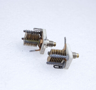
Figure 14: Air Variable Capacitor (CB)
Their advantages: A symphony of easy adjustment, unwavering stability, robust durability, and an impressive resistance to wear and tear. However, air variable capacitors, when juxtaposed with their counterparts, unveil a notable disadvantage: their comparatively larger size.
Application Areas
Radio technicians cherish them for tuning, and selecting diverse broadcast frequencies with finesse. In electronic instruments, especially those requiring high-frequency measurement, these capacitors shine, ensuring precise control over capacitance values. High-frequency signal generators and communication electronics also rely on them to finetune signal frequencies.
Technical Challenges and Future Development
Miniaturization looms as a challenge. Despite their sterling performance in high-frequency realms, their bulkiness is a hindrance in smaller devices. The future beckons with promises of size reduction, and maintaining performance.
Accuracy improvement is also pivotal. The quest for more refined adjustment mechanisms continues, striving to meet high-precision demands.
Exploring new frontiers, the application of innovative materials and structural designs could significantly enhance performance and longevity.
Despite their size, air variable capacitors excel in high-frequency circuits for their adjustability, reliability, and durability. Expected technological breakthroughs include size reduction, increased precision, and material innovation to adapt them to modern electronic needs. These improvements, particularly in wireless communications and high-frequency test equipment, will ensure their continued relevance.
Thin Film Variable Capacitors
Construction and Material Properties
At the heart of thin film variable capacitors lies a high-quality plastic film, serving as the dielectric nestled between the rotor and the stator. This film is not only a robust dielectric but also offers commendable physical stability. Encased often in a shell of transparent or translucent plastic, these capacitors aren't just physically shielded; their inner workings remain visible for straightforward observation and tweaking.
Design and Type
Sealed double or quadruple variable capacitors stand out. The double variant boasts two adjustable capacitor banks, aligning with more intricate circuits. Meanwhile, the quadruple version, with its plethora of adjustment options, is a staple in sophisticated devices like AF/FM multi-band radios.
Consider their volume and weight. Their design ethos? Miniaturization and lightness. This renders them ideal for applications where space is at a premium and weight is a critical factor.
Figure 15: Thin Film Variable Capacitors
Advantages and Disadvantages
Advantages include their compact stature and featherlight nature, making them a perfect match for contemporary electronic gadgets. Their forte? Precise capacitance adjustments.
However, they have their Achilles' heel: susceptibility to wear, particularly in environments marked by high frequencies or elevated temperatures.
Application Areas
In the realm of radio, single connection models reign supreme for basic tuning tasks.
Electronic Instruments and Equipment: Here, dual-connection models come into play, integral to transistor radios and various electronic devices needing finer adjustment.
In the more complex territory of AF/FM multi-band radios, quadruple connection capacitors are the linchpins, offering multi-band tuning.
Technical Challenges and Future Development
The roadmap ahead? Developing materials that are both more resistant to wear and more stable, thereby bolstering the long-term reliability of these capacitors. The precision adjustment mechanism is also in line with an upgrade, aiming for even more accurate capacitance tuning to satisfy the demands of high-precision electronics.
Furthermore, miniaturization and integration are key goals, in adapting to the evolving landscape of modern electronic devices.
Thin film variable capacitors are small and lightweight in modern electronics, especially where volume and weight constraints are combined with the need for precise capacitance tuning. Their design and functional optimizations address wear and space efficiency issues and simplify capacitance adjustment for users. Going forward, the trajectory of these capacitors will be toward improved durability, improved adjustment accuracy, and further miniaturization and integration. This is to meet the growing demand for high-performance, reliable capacitors in advanced electronic equipment. As technological innovation continues to develop, thin film variable capacitors are expected to expand their applications in increasingly complex electronic devices.
Conclusion
In summary, capacitors, as foundational elements of electronic technology, showcase a dynamic array of types and advancements, each heralding new growth possibilities in the electronics sector. From the simplicity of ceramics to the complexity of the metalized paper and trimmer capacitors, each variety brings its own set of benefits and suitable applications. Facing future hurdles like miniaturization, enhanced temperature resistance, cost reduction, and improved accuracy, the ongoing evolution of capacitor technology is set to elevate electronic equipment performance and broaden their application range. The infusion of novel materials and cutting-edge technologies signifies that capacitors will continue to be pivotal in the forward march of electronic technology.
About us
ALLELCO LIMITED
Read more
Quick inquiry
Please send an inquiry, we will respond immediately.
A Comprehensive Guide to Photoresistors: Definitions, Types, Operating Mechanisms, and Applications
on January 20th
Guidelines for the use of leaded and lead-free solder
on January 17th
Popular Posts
-

What is GND in the circuit?
on January 1th 2946
-

RJ-45 Connector Guide: RJ-45 Connector Color Codes, Wiring Schemes, R-J45 Applications, RJ-45 Datasheets
on January 1th 2502
-

Fiber Connector Types: SC Vs LC And LC Vs MTP
on January 1th 2091
-

Understanding Power Supply Voltages in Electronics VCC, VDD, VEE, VSS, and GND
on November 9th 1898
-

Comparison Between DB9 and RS232
on January 1th 1765
-

What Is An LR44 Battery?
Electricity, that ubiquitous force, quietly permeates every aspect of our daily lives, from trivial gadgets to life-threatening medical equipment, it plays a silent role. However, truly grasping this energy, especially how to store and efficiently output it, is no easy task. It is against this background that this article will focus on a type of coin cell battery that may seem insignificant on the...on January 1th 1714
-

Understanding the Fundamentals:Inductance Resistance, andCapacitance
In the intricate dance of electrical engineering, a trio of fundamental elements takes center stage: inductance, resistance, and capacitance. Each bears unique traits that dictate the dynamic rhythms of electronic circuits. Here, we embark on a journey to decipher the complexities of these components, to uncover their distinct roles and practical uses within the vast electrical orchestra. Inductan...on January 1th 1662
-

CR2430 Battery Comprehensive Guide: Specifications, Applications and Comparison to CR2032 Batteries
What is CR2430 battery ?Benefits of CR2430 BatteriesNormCR2430 Battery ApplicationsCR2430 EquivalentCR2430 VS CR2032Battery CR2430 SizeWhat to look for when buying the CR2430 and equivalentsData Sheet PDFFrequently Asked Questions Batteries are the heart of small electronic devices. Among the many types available, coin cells play a crucial role, commonly found in calculators, remote controls, and ...on January 1th 1567
-

What Is RF and Why Do We Use It?
Radio Frequency (RF) technology is a key part of modern wireless communication, enabling data transmission over long distances without physical connections. This article delves into the basics of RF, explaining how electromagnetic radiation (EMR) makes RF communication possible. We will explore the principles of EMR, the creation and control of RF signals, and their wide-ranging uses. The article ...on January 1th 1550
-

CR2450 vs CR2032: Can The Battery Be Used Instead?
Lithium manganese batteries do have some similarities with other lithium batteries. High energy density and long service life are the characteristics they have in common. This kind of battery has won the trust and favor of many consumers because of its unique safety. Expensive tech gadgets? Small appliances in our homes? Look around and you'll see them everywhere. Among these many lithium-manganes...on January 1th 1519
HOT Part Number
-

FDD8586
Fairchild Semiconductor
MOSFET N-CH 20V 35A TO252AA
UPD70F3740GC-UEU-AX
Renesas Electronics America Inc
IC MCU 32BIT 512KB FLASH 100LQFP
HI3-574AKN-5Z
Renesas Electronics America Inc
IC ADC 12BIT SAR 28DIP
TPD1S514-2YZR
Texas Instruments
IC USB CHARGER OVP 12DSBGA
MAX6604AATA+T
Analog Devices Inc./Maxim Integrated
IC TEMP SENSOR DDR MEMORY 8TDFN
12061A332JAT2A
AVX Corporation
CAP CER 3300PF 100V C0G/NP0 1206
SN74AHC126NSR
Texas Instruments
IC BUFFER NON-INVERT 5.5V 14SOP
ISL85003AFRZ-T7A
Renesas Electronics America Inc
IC REG BUCK ADJUSTABLE 3A 12DFN
AD7533UQ
Analog Devices Inc.
IC DAC 10BIT A-OUT 16CDIP
CL10B472KB8NNND
Samsung Electro-Mechanics
CAP CER 4700PF 50V X7R 0603
TPS2049DR
Texas Instruments
IC PWR SWITCH N-CHAN 1:1 8SOIC
XC18V04VQ44C
AMD
IC PROM SRL FOR 4M GATE 44-VQFP
VB40100G-E3/8W
Vishay General Semiconductor - Diodes Division
DIODE ARRAY SCHOTTKY 100V TO263
ADP3338AKC-3-RL
Analog Devices Inc.
IC REG LINEAR 3V 1A SOT223-3
ALT80802KEJJTR
Allegro MicroSystems
IC LED DRIVER RGLTR PWM 2A 10DFN
FT838D2-BL-RT
Fremont Micro Devices Ltd
IC OFFLINE SW FLYBACK SOT23-5
UC3852DTR
Texas Instruments
IC PFC CTRLR CCM 200KHZ 8SOIC
M74HC573TTR
STMicroelectronics
IC LATCH OCTAL D 3STATE 20-TSSOP -
AD7690BCPZ-R2
Analog Devices Inc.
IC ADC 18BIT 10LFCSP
74LVT162244MTDX
onsemi
IC BUF NON-INVERT 3.6V 48TSSOP
1N2436
Microchip Technology
DIODE GEN PURP 50V 150A DO205AA
FWP-175A
Eaton - Bussmann Electrical Division
FUSE CARTRIDGE 175A 700VAC/VDC
KSE13003TH1ATU
Fairchild Semiconductor
TRANS NPN 400V 1.5A TO220-3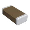
GRM3195C1H133JA01D
Murata Electronics
CAP CER 0.013UF 50V C0G/NP0 1206
PIC32MX210F016B-I/SP
Microchip Technology
IC MCU 32BIT 16KB FLASH 28SPDIP
AON7448
Alpha & Omega Semiconductor Inc.
MOSFET N-CH 80V 7.1A/24A 8DFN
BLF8G38LS-75V
Ampleon USA Inc.
RF FET LDMOS 75V SOT1239B
BLM15AG221SN1D
Murata Electronics
FERRITE BEAD 220 OHM 0402 1LN
MAX526CCWG+
Analog Devices Inc./Maxim Integrated
IC DAC 12BIT V-OUT 24SOIC
MAX5035DASA
Analog Devices Inc./Maxim Integrated
IC REG BUCK ADJUSTABLE 1A 8SOIC
ST72F561AR9TAE
STMicroelectronics
IC MCU 8BIT 60KB FLASH 64LQFP
SPC18P8LM4H-1
Knowles
MIC MEMS DIGITAL PDM OMNI -26DB
FAN3227CMX-F085
onsemi
IC GATE DRVR LOW-SIDE 8SOIC
WP7-P024VA1-R6000
JAE Electronics
CONN PLUG 24POS SMD GOLD
SN74LV165ADBR
Texas Instruments
IC REGISTR PAR-LOAD 8BIT 16SSOP
HD49338HFEB-E
Renesas Electronics America Inc
PGA & 12-BIT A/D CONVERTER -

LTC3862EGN-1#PBF
Analog Devices Inc.
IC REG CTRLR BOOST/SEPIC 24SSOP
LM3676SD-1.8
Texas Instruments
IC REG BUCK 1.8V 600MA 8WSON
BCM56744A1KFRBLG
Broadcom Limited
MULTI LAYER SWITCH
CL10B102KC8WPJC
Samsung Electro-Mechanics
CAP CER 1000PF 100V X7R 0603
PI3PCIE3412AZHEX
Diodes Incorporated
PCI SWITCH 2:1 4 CHAN 42TQFN
MMBZ5230BLT1
onsemi
DIODE ZENER 4.7V 225MW SOT23-3
TL1451ACPWRG4
Texas Instruments
IC REG CTRLR MULT TOP 16TSSOP
TPS53114PWR
Texas Instruments
IC REG CTRLR BUCK 16HTSSOP
BD3843FS-E2
Rohm Semiconductor
IC SOUND PROCESSOR 6CH 24SSOP
MT29F8G08ABACAH4-IT:C
Micron Technology Inc.
IC FLASH 8GBIT PARALLEL 63VFBGA
1SMA70AT3G
onsemi
TVS DIODE 70VWM 113VC SMA
TLA2528IRTET
Texas Instruments
IC SOC PROCESSOR
BXB75-48S12FLTJ
Artesyn Embedded Power
DC DC CONVERTER 12V 75W
R5F51303ADFK#30
Renesas Electronics America Inc
IC MCU 32BIT 64KB FLASH 64LQFP
APX803S00-31SA-7
Diodes Incorporated
IC SUPERVISOR 1 CHANNEL SOT23
LNK584DG
Power Integrations
IC OFFLINE SWITCH FLYBACK 8SO
MTFC128GAJAECE-5M AIT
Micron Technology Inc.
IC FLASH 1TB MMC 169LFBGA
HFA1113MJ/883
Harris Corporation
IC BUFFER 1 CIRCUIT 8CERDIP