Guide to Ceramic Capacitor Types
The type of ceramic used in these electronic components offers several benefits including low energy loss and a reasonable degree of stability. However, these benefits can vary depending on the ceramic material chosen. Ceramic capacitors are named after the ceramic materials they are made from. These materials consist of finely ground para-electric or ferro-electric particles, mixed with other substances to get the right properties. This article takes a closer look of ceramic capacitors, discussing different types like disc ceramic capacitors, Multi-Layer Ceramic Capacitors (MLCCs), and feedthrough capacitors, each designed for specific electronic uses. It also explains how ceramic dielectrics are classified into groups such as Class 1 and Class 2, pointing out their unique features, temperature responses, and capacitance behavior. The article talk about how capacitor technology has evolved, improving performance to meet the needs of high-frequency and precise electronic circuits.Catalog
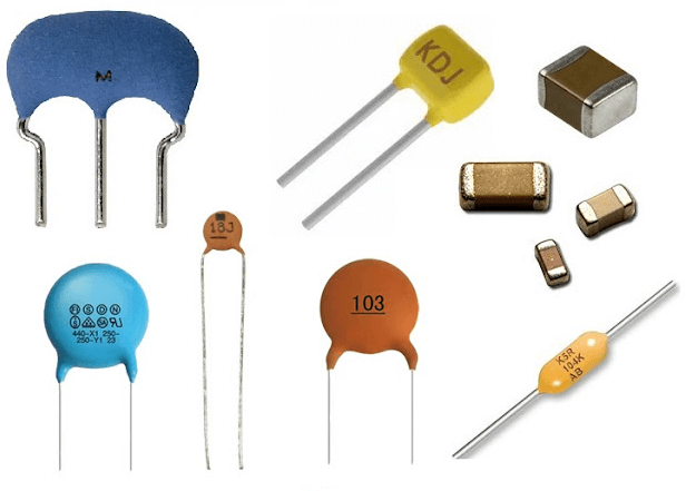
Figure 1: Ceramic Capacitors
Disc Ceramic Capacitor
The disc ceramic capacitor is easily to recognized by its round shape and strong build. The main part of this capacitor is a ceramic disc and acts as the insulating material to work. The capacitor’s performance depends a lot on how the electrodes are applied to this disc. These electrodes are carefully placed on the surface to ensure good conductivity.
Once the electrodes are in place, leads are attached. These leads are good for establishing electrical connections, making sure the capacitor can be integrated into a circuit effectively. Feature of the disc ceramic capacitor is the resin coating that covers it completely. This coating plays multiple roles: it shields the component from physical damage, protects against environmental factors like moisture, and maintains electrical performance by preventing contamination.
Because of their strong design, disc ceramic capacitors are very reliable and long-lasting, making them a popular choice in different industries like consumer electronics, car systems, and industrial equipment.
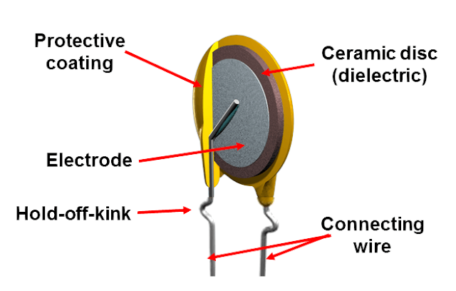
Figure 2: Disc Ceramic Capacitor Structure
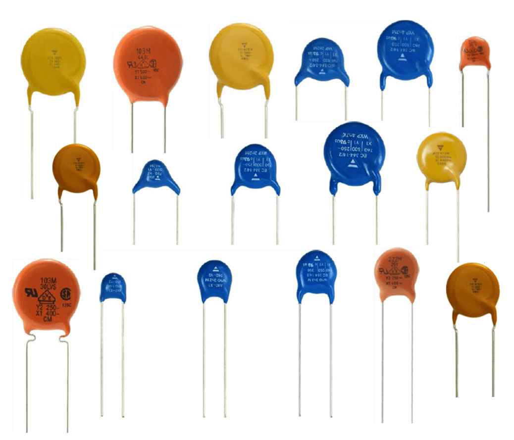
Figure 3: Disc Ceramic Capacitor
MLCC Capacitor
The Multi-Layer Ceramic Capacitor (MLCC) is a main component in modern electronics, especially in surface-mounted technology (SMT). This capacitor consists of several layers of ceramic dielectric material, stacked to maximize capacitance in a compact form. The layered structure is carefully designed with metallic electrodes placed between the layers. These electrodes create parallel connections, enhancing the capacitor's efficiency.
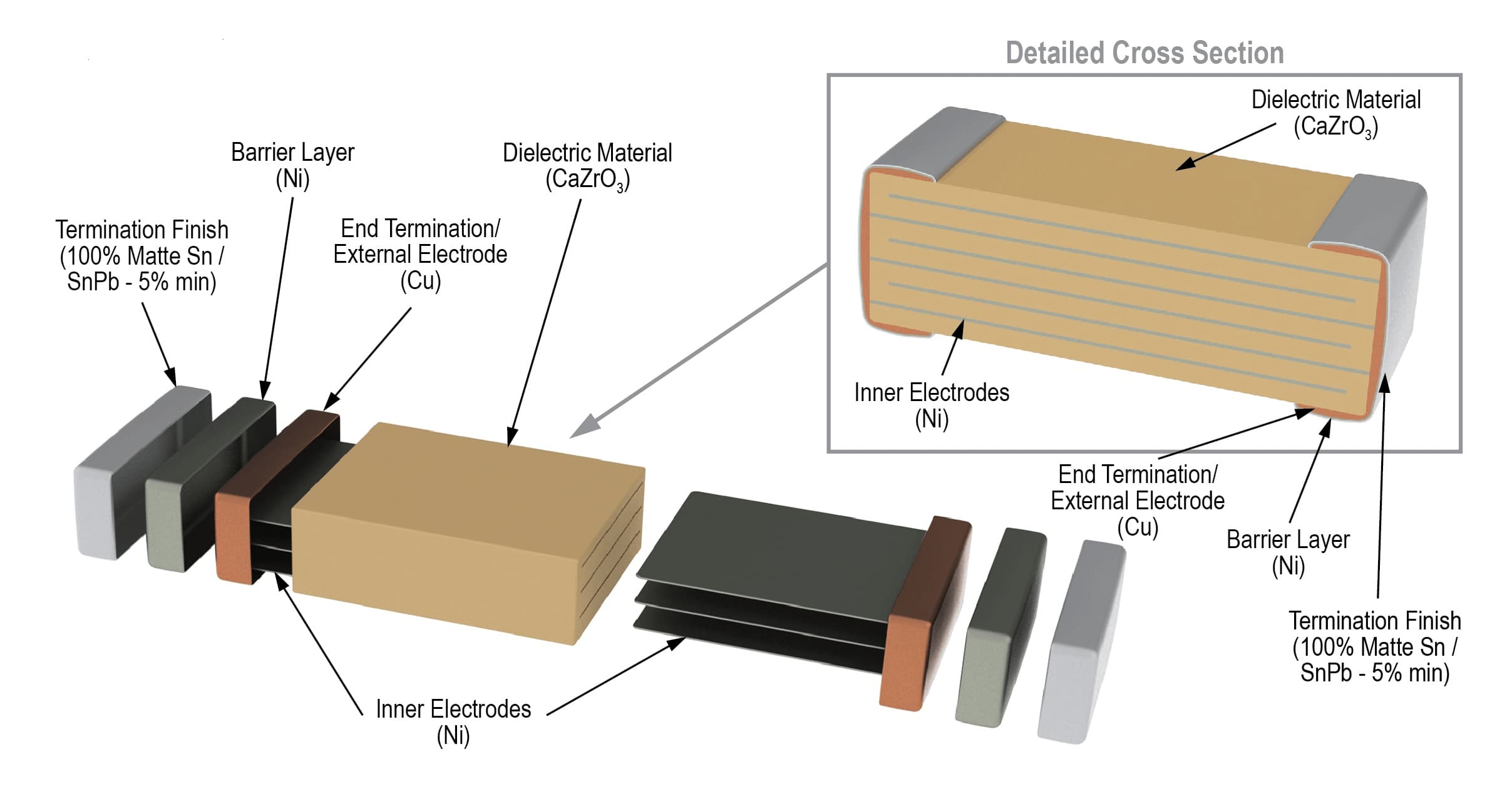
Figure 4: MLCC Capacitor Structure
MLCCs are well-suited for applications where high capacitance and minimal physical space are required. In surface mount configurations, the end terminations of MLCCs are engineered with precision to ensure strong mechanical attachment and excellent electrical connectivity on printed circuit boards (PCBs). These terminations are made from a combination of metals, such as silver and palladium, and are then coated with nickel and tin. This coating improves solderability and protects against oxidation.
Advances in MLCC technology, including the use of high-k dielectrics and refined layering techniques, have greatly improved their performance. As a result, MLCCs are now required in high-density electronic circuits used in many modern devices.
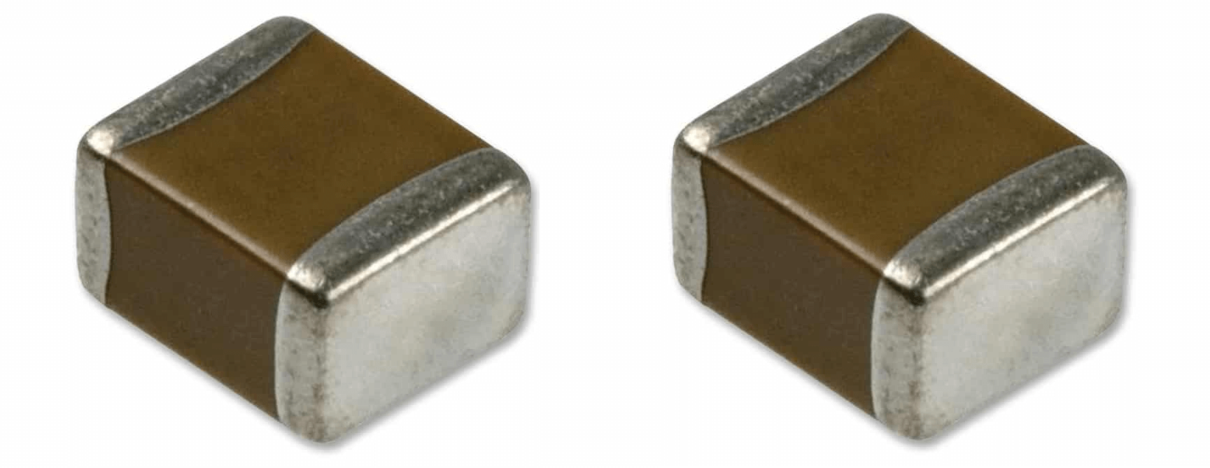
Figure 5: MLCC Capacitor
Feedthrough Capacitor
Feedthrough capacitors are important in advanced electronics because they help block interference in situations where cables or wires pass through shielded areas. These capacitors are designed to maintain signal integrity by filtering out radio frequency (RF) and electromagnetic interference (EMI).
The development of ceramic capacitors has greatly influenced the evolution of feedthrough capacitors. Modern feedthrough designs incorporate advanced dielectric materials, allowing them to operate effectively at RF and microwave frequencies. These capacitors are also designed to tolerate voltage fluctuations and maintain stable performance under varying thermal conditions.
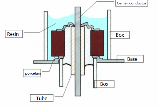
Figure 6: Feedthrough Capacitor Structure
Innovations in materials and manufacturing techniques have not only improved the performance of feedthrough capacitors but have also kept them cost-effective for mass production. As a result, these capacitors are increasingly used in telecommunications, aerospace, and defense industries. The ongoing improvement of feedthrough capacitors highlights how need they are in the progress of electronic technology.
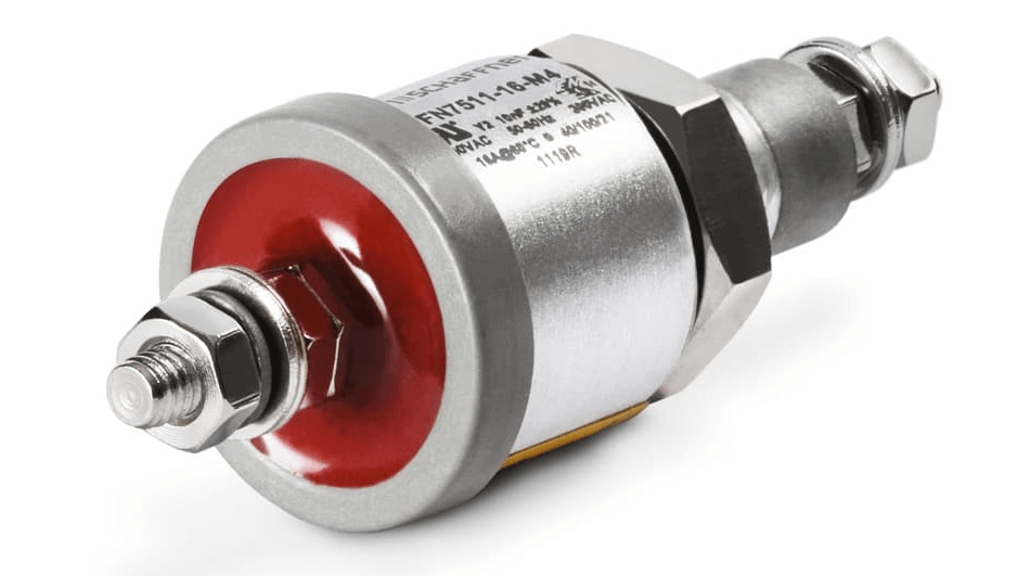
Figure 7: Feedthrough Capacitor
Ceramic Dielectric Types
Ceramic capacitors use different types of materials for insulation and each type is labeled with codes like C0G, NP0, X7R, Y5V, and Z5U. These codes aren't random, they indicate how the material reacts to changes in temperature and voltage. To help people pick the right capacitors, industry groups created different categories for ceramic dielectrics. These categories organize the types of dielectrics used in ceramic capacitors according to how they are meant to be used.
To help people pick the right capacitors, industry groups created different categories for ceramic dielectrics. These categories organize the types of dielectrics used in ceramic capacitors according to how they are meant to be used.
Class 1 Ceramic Capacitor Dielectric
Class 1 ceramic capacitors are known for their outstanding performance, due to their use of class 1 dielectrics. These dielectrics offer remarkable stability and minimal losses, good in precision applications like oscillators and filters. The reliability of these capacitors comes from their ability to maintain performance across a wide range of environmental conditions.
The exceptional performance of class 1 dielectrics stems from their specific composition. They are composed of finely milled Titanium dioxide (TiO2), then blended with various additives to enhance electrical properties. Additives include Zinc, Zirconium, Niobium, Magnesium, Tantalum, Cobalt, and Strontium. Each of these elements plays a role in improving the capacitor's stability and efficiency. In recent years, the use of rare earth oxides such as neodymium and samarium has become more common in C0G (NP0) dielectrics. These materials are prized for their ability to maintain stability and minimize signal loss for preserving the integrity of electrical signals in high-precision circuits.
Figure 8: Class 1 Ceramic Capacitor Dielectric
Class 1 Capacitor Codes
The performance characteristics of class 1 ceramic capacitors are clearly indicated by a standardized three-character code. This code provide a quick and reliable reference to the capacitor's behavior in response to temperature variations.
The first character in the code is a letter that indicates how much the capacitance will change with temperature, measured in parts per million per degree Celsius (ppm/°C).
The second character is a number that acts as a multiplier, giving more detail on how capacitance shifts with temperature.
The third character is another letter that specifies the maximum allowable error in capacitance variation per degree Celsius.
To fully understand these codes, a detailed table is often used, breaking down each specification.
|
FIRST CHARACTER |
SECOND CHARACTER |
THIRD CHARACTER |
|||
|
Letter |
Sig Figs |
Digit |
Multiplier 10x |
Letter |
Tolerance |
|
C |
0 |
0 |
-1 |
G |
+/-30 |
|
B |
0.3 |
1 |
-10 |
H |
+/-60 |
|
L |
0.8 |
2 |
-100 |
J |
+/-120 |
|
A |
0.9 |
3 |
-1000 |
K |
+/-250 |
|
M |
1 |
4 |
1 |
L |
+/-500 |
|
P |
1.5 |
6 |
10 |
M |
+/-1000 |
|
R |
2.2 |
7 |
100 |
N |
+/-2500 |
|
S |
3.3 |
8 |
1000 |
- |
- |
|
T |
4.7 |
- |
- |
- |
- |
|
V |
5.6 |
- |
- |
- |
- |
|
U |
7.5 |
- |
- |
- |
- |
Class 1 Capacitor Types
NP0 (Negative-Positive-Zero) or C0G
The C0G type is highly stable and barely changes with temperature. It has an error margin of just ±30ppm/°C, making it a very reliable material in the EIA Class 1 ceramic category. The C0G (NP0) material keeps its capacitance nearly constant across a wide temperature range with less than ±0.3% variation between -55°C and +125°C. Its capacitance change or hysteresis is minimal under ±0.05%, which is much better than the up to ±2% change seen in some film capacitors. C0G (NP0) capacitors also have a high "Q" factor, often over 1000, indicating excellent performance with minimal loss. This high "Q" remains stable across different frequencies. C0G (NP0) has very low dielectric absorption, less than 0.6%, similar to mica, known for low absorption.
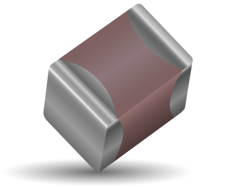
Figure 9: NP0 (Negative-Positive-Zero) or C0G
N33
The N33 capacitor has a temperature coefficient of +33 ppm/°C, means its capacitance slowly increases as the temperature goes up in a steady and predictable way. This makes the N33 a good choice for situations where some change in capacitance with temperature is okay, but you still need overall stability. The N33 is found in temperature compensation circuits. Here, it’s changing capacitance helps balance out temperature-related changes in other parts of the circuit, keeping the whole system working well. The capacitance of the N33 usually ranges from a few picofarads to about 1 microfarad, which is normal for Class 1 capacitors. What makes the N33 special is its predictable reaction to temperature changes. Even its slight dependence on temperature, the N33 keeps low energy loss and high stability and make it a dependable option for high-frequency and precision electronic circuits.
P100, N150, N750, S2R
Temperature labels like P100, N150, N750, and S2R tell us how a capacitor’s performance changes with temperature. These labels have two parts: a letter and a number.
The letter shows if the capacitor’s ability to hold a charge (capacitance) will increase, decrease, or fluctuate with temperature:
"P" means capacitance increases as temperature goes up.
"N" means capacitance decreases as temperature rises.
"S" means capacitance can either increase or decrease, depending on the temperature change.
The number tells us how much the capacitance changes per degree Celsius. For example, a P100 capacitor will increase its capacitance by 100 parts per million (ppm) for each degree Celsius rise in temperature. These capacitors are chosen for situations where some change in capacitance due to temperature is okay. They’re useful for less tasks, like filtering or timing, where minor changes won’t cause problems and can even save on costs. In contrast, NP0/C0G capacitors are used for tasks where stability is required because they don’t change with temperature.
Class 2 Ceramic Capacitor Dielectric
Class 2 ceramic capacitors are made from ferroelectric materials like barium titanate (BaTiO3). These materials give the capacitors a high dielectric constant, that is much higher than what you find in Class 1 ceramics. This higher dielectric constant means Class 2 capacitors can store more electrical charge in a smaller volume, making them perfect for applications that need high capacitance in compact spaces, such as power supply filters and energy storage systems.
However, the high permittivity of Class 2 materials also introduces some challenges. The capacitance of these capacitors can vary with temperature, voltage, and aging. For example, their capacitance is not consistent across different temperatures and it can change with the voltage applied. Class 2 dielectrics are further divided based on how stable they are with temperature changes. 'Stable Mid-K' ceramics have dielectric constants between 600 and 4000 and maintain their capacitance with a temperature variation of up to ±15%. On the other hand, 'High K' ceramics have dielectric constants between 4000 and 18,000 but are more sensitive to temperature changes that restricts their use to environments where the temperature doesn't fluctuate much.
Class 2 Capacitor Codes
In Class 2 ceramic capacitors, a three-character code is used to describe how the material behaves.
The first character is a letter that shows the lowest temperature the capacitor can work at.
The middle character is a number that tells the highest temperature it can handle.
The last character, another letter, indicates how much the capacitance changes over the temperature range. The meanings of these codes are explained in the table that comes with it.
|
FIRST CHARACTER |
SECOND CHARACTER |
THIRD CHARACTER |
|||
|
Letter |
Low Temp |
Digit |
High Temp |
Letter |
Change |
|
X |
-55C (-67F) |
2 |
+45C (+113F) |
D |
+/-3.3% |
|
Y |
-30C (-22F) |
4 |
+65 (+149F) |
E |
+/-4.7% |
|
Z |
+10C (+50F) |
5 |
+85 (+185F) |
F |
+/-7.5% |
|
- |
- |
6 |
+105 (+221F) |
P |
+/-10% |
|
- |
- |
7 |
+125 (+257F) |
R |
+/-15% |
|
- |
- |
- |
- |
S |
+/-22% |
|
- |
- |
- |
- |
T |
-0.66666667 |
|
- |
- |
- |
- |
U |
-0.39285714 |
|
- |
- |
- |
- |
V |
-0.26829268 |
Class 2 Capacitor Types
X7R capacitors work well over a wide temperature range, from -55°C to +125°C. Within this range, their capacitance only changes by about ±15%, though it can decrease over time due to aging. These capacitors are useful in power supplies, decoupling, and bypass circuits, where consistent performance even temperature changes is required. While they may not be the best for applications needing exact capacitance, they are reliable for general electronic use in environments with varying but not extreme temperatures.
X5R capacitors are similar to X7R capacitors but operate within a slightly narrower temperature range, from -55°C to +85°C. This means they are less ideal for high-temperature environments. However, they are still used in consumer electronics like mobile devices and laptops, where temperature changes are moderate. X5R capacitors keep their capacitance stable within ±15% across their temperature range, making them good for tasks like smoothing and decoupling in everyday indoor settings.
Y5V capacitors work within a limited temperature range, from -30°C to +85°C, and their capacitance can vary widely, from +22% to -82%. Because of this large variation, they are best for applications where exact capacitance isn't required. These capacitors are found in less demanding areas of commercial electronics. They're often used in toys and general consumer products where environmental conditions are controlled.
Z5U capacitors operate in a narrow temperature range of +10°C to +85°C, with capacitance changes ranging from +22% to -56%. They are used in consumer electronics where cost is more important than precise stability. While Z5U capacitors aren't as reliable under environmental stress, they work fine in stable, predictable conditions. They're typically used in audio and video equipment or low-end consumer gadgets.

Figure 10: Z5U Capacitors
Class 3 Ceramic Capacitor Dielectric
Class 3 ceramic capacitors stand out for their extremely high permittivity, sometimes reaching values 50,000 times greater than some Class 2 ceramics. This allows them to achieve very high capacitance levels, making them suitable for specialized applications that require substantial capacitance, such as power transmission systems and high-energy physics experiments.
Class 3 capacitors have disadvantages. They are not very accurate or stable with non-linear temperature characteristics and high losses that can worsen over time. These capacitors cannot be used in multilayer manufacturing that excludes them from being made in surface mount technology (SMT) formats. As modern electronic devices increasingly rely on SMT for miniaturization and improved performance, the use of Class 3 ceramics has declined. This trend is also reflected in the fact that major standardization bodies like the IEC and EIA no longer standardize these capacitors, pointing to a move towards more reliable and stable technologies.
Class 3 Capacitor Types
|
Code |
Temperature
Range |
Capacitance
Change |
Applications |
|
Z5P |
+10°C to +85°C |
+22%, -56% |
Used in consumer electronics and power supply circuits. |
|
Z5U |
+10°C to +85°C |
+22%, -82% |
Ideal for timing circuits and filters. |
|
Y5P |
-30°C to +85°C |
+22%, -56% |
Suitable for general-purpose use, particularly for DC blocking. |
|
Y5U |
-30°C to +85°C |
+22%, -82% |
Used in coupling and bypass capacitor applications. |
|
Y5V |
-30°C to +85°C |
+22%, -82% |
Used for energy storage and smoothing applications. |
Class 4 Ceramic Capacitor Dielectric
Class 4 ceramic capacitors, once known as barrier layer capacitors, used high permittivity dielectrics similar to those in Class 3 capacitors. Although these materials offered high capacitance, advancements in capacitor technology have led to their gradual phase-out.
The move away from Class 4 dielectrics is a sign of how electronic components continue to evolve. Newer capacitor technologies now focus not only on fitting within specific physical dimensions but also on meeting the operational demands of modern electronic circuits. This shift highlights the continuous innovation in electronic materials with new and more efficient dielectrics being created to meet the evolving standards and performance demands of the industry.
Advantages of Ceramic Capacitors
• Ceramic capacitors are inexpensive to produce, making them an affordable choice for many electronic devices, from everyday gadgets to industrial machinery.
• Ceramic capacitors perform very well in high-frequency situations. They have low parasitic inductance and resistance that makes them great for fast, high-speed circuits.
• Ceramic capacitors have low ESR, boosts circuit efficiency by reducing energy loss. This is helpful in voltage regulation and power supply circuits.
• Ceramic capacitors are non-polarized, meaning they can be used in AC circuits or where the voltage direction might change, unlike electrolytic capacitors.
• Ceramic capacitors come in various packaging styles, including leaded and Surface-Mount Device (SMD) forms like MLCCs, making them easy to use in different electronic designs.
• Ceramic capacitors are reliable and durable, performing well under various environmental conditions. Unlike electrolytic capacitors, they are resistant to leakage and drying out.
Disadvantages of Ceramic Capacitors
• Ceramic capacitors don't provide high capacitance like electrolytic capacitors. This limits their use in areas needing large capacitance, such as power filters or audio circuits.
• The capacitance of ceramic capacitors can change with temperature. For example, Y5V capacitors may have large variations, potentially affecting circuit performance if not properly managed.
• Ceramic capacitors may experience changes in capacitance with different voltage levels, known as the DC bias effect that can reduce their effectiveness under various conditions.
• Ceramic capacitors can be brittle. Multi-Layer Ceramic Capacitors (MLCCs) are prone to cracking due to physical stress, like flexing of the circuit board or rough handling.
Conclusion
The discussion around ceramic capacitors highlights their role in reducing electromagnetic interference, improving signal quality, and keeping circuits stable. As technology advances, it's important to keep improving the materials and manufacturing methods for ceramic capacitors to meet the growing demands of modern electronics. This article not only explains the technical details and types of ceramic capacitors but also emphasizes their importance in making electronic devices more efficient and reliable in today's fast-paced tech world.
Frequently Asked Questions [FAQ]
1. How do you identify a ceramic capacitor?
To identify a ceramic capacitor, look for a small, disc-shaped or layered component. Unlike electrolytic capacitors, ceramic capacitors don't have polarity markings. They might have codes or numbers that show capacitance, voltage rating, or tolerance. These markings are often in a standard format, like EIA. You can use a multimeter set to measure capacitance to confirm if it's a ceramic capacitor. If you don't have a multimeter, you can also check its appearance and compare the codes with a capacitor chart or datasheet to verify.
2. Is X7R better than Y5V?
Deciding between X7R and Y5V capacitors depends on what you need them for. X7R capacitors are better if you need stable performance across a wide temperature range (-55°C to +125°C) with only small changes in capacitance (±15%). On the other hand, Y5V capacitors have a much bigger change in capacitance with temperature (+22/-82%) and work in a smaller temperature range (-30°C to +85°C). So, X7R is the better choice for tougher conditions where stability matters.
3. Is X8R better than X7R?
X8R is not a common designation in the standard capacitor classifications. If referring to a capacitor that operates over a broader temperature range than X7R, it would be better in applications where extreme temperatures are expected. However, since X8R is not standard, X7R remains the more reliable and preferable choice due to its known and stable characteristics.
4. Can I replace a ceramic capacitor with a higher uF?
Yes, you can replace a ceramic capacitor with one of a higher capacitance (µF) as long as the voltage rating and other operational parameters match the circuit requirements. This is often done to achieve better performance or accommodate component availability. However, ensure that the physical size and frequency characteristics fit the application, as these might affect the circuit.
5. Can I replace ceramic capacitor with film capacitor?
Yes, replacing a ceramic capacitor with a film capacitor is feasible. Film capacitors offer better tolerance, lower losses, and more stability over time and temperature compared to ceramic capacitors. Ensure that the voltage and capacitance ratings are compatible. Film capacitors are often larger, so consider the physical space in your design.
6. Can I use a 440v capacitor instead of a 370v?
Yes, using a capacitor with a higher voltage rating (440V) instead of a lower one (370V) is generally safe. The higher voltage rating means the capacitor can handle higher potential differences without risk of failure. Always ensure that the capacitance and other specifications meet the circuit’s requirements.
7. Can I replace a 250v capacitor with a 450V?
Yes, it is safe to replace a 250V capacitor with a 450V capacitor. The higher voltage rating provides a greater margin of safety as the capacitor can withstand higher voltages. As with other replacements, verify that the capacitance, physical size, and other specifications match the needs of your application, to maintain the functionality and safety of your electronic device.