How Does a Digital Multimeter Works?
Digital multimeters (DMMs) are handy tools used by people who work with electrical systems, whether they're fixing things around the house or dealing with bigger electrical setups in factories. These devices are used to measure things like voltage (the force pushing electricity through a wire), current (how much electricity is flowing), and resistance (how hard it is for electricity to flow). Compared to older, analog multimeters with a needle and dial, DMMs are more accurate and offer more features thanks to their digital technology. Whether you're trying to fix a problem in a circuit or checking if a wire is connected properly, learning how a DMM works will help you use it correctly and safely.Catalog
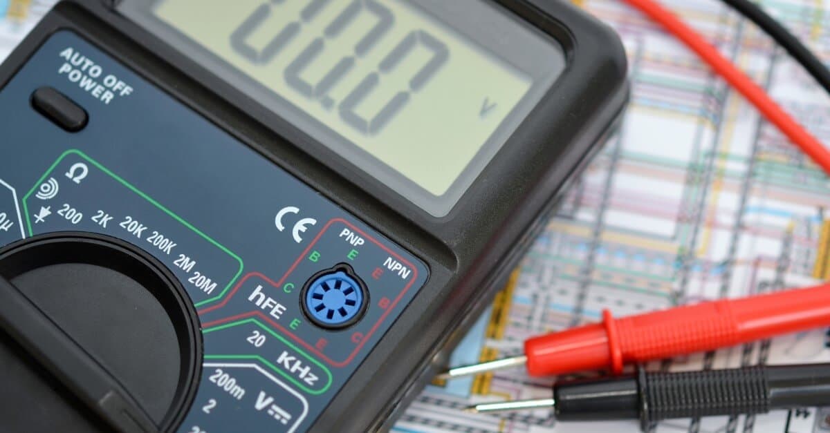
Figure 1: Digital Multimeter
Introduction to Digital Multimeters
Digital multimeters (DMMs) are widely used in a variety of electrical and electronic tasks, ranging from simple home circuits to more complicated industrial systems. Unlike older analogue models, which have a needle and dial, DMMs use digital technology to offer better accuracy and more features. These devices measure three main electrical properties:
• Voltage (Volts, V): The force that pushes electrical current through a circuit.
• Current (Amperes, A): The amount of electric charge flowing through a wire or conductor.
• Resistance (Ohms, Ω): How much a material or component resists the flow of electricity.
Depending on the model, DMMs can also measure other things like capacitance (how much charge something can store), temperature, frequency (how often an electrical signal repeats), and continuity (whether a circuit is complete and electricity can flow through it).
Key Components and Functions of a Digital Multimeter (DMM)
Digital Multimeters (DMMs) are tools that help measure electrical quantities like voltage, current, and resistance. Different parts of a DMM work together to make sure it gives accurate readings. Understanding these parts makes it easier to use the device properly. Let's break down some of the most basic parts and how they work.
Analog to Digital Conversion (ADC)
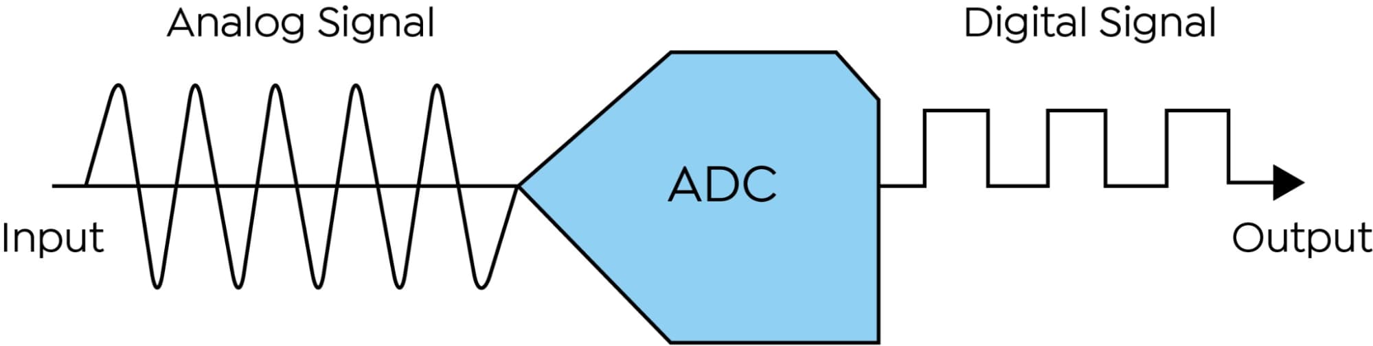
Figure 2: Digital Multimeter Measuring DC and AC Voltage
At the core of every DMM is a component called an Analog-to-Digital Converter (ADC). This part changes the continuous electrical signals (like voltage or current) into numbers that show up on the screen. One common type of ADC used in DMMs is called a Successive Approximation Register (SAR).
The SAR ADC works by gradually narrowing down the input voltage until it finds the correct number to represent the electrical signal. It does this by first "sampling" or capturing the voltage, then holding that value steady while converting it into a digital number. The detail and accuracy of this process depend on the ADC’s resolution, which is usually measured in bits. A typical DMM has a 16-bit resolution, which gives a good balance between speed and accuracy. Higher resolutions allow for more detailed readings but can take longer, while lower resolutions give quicker results but may miss smaller changes in the signal.
Measurement Accuracy and Resolution
Accuracy is how close the DMM's reading is to the actual value of the signal. For example, if you are measuring a voltage of 5.00 volts, an accurate DMM will show a result that is nearly the same as 5.00 volts.
Resolution, on the other hand, is the smallest change the DMM can notice. If a DMM has a resolution of 0.01 volts, it means the device can detect changes as small as one-hundredth of a volt. This is helpful when you need to see very small changes in the signal.
Some advanced DMMs include features like buffering and averaging to improve their performance. Buffering helps keep the signal steady, while averaging takes multiple readings and smooths out the result. This reduces small, unwanted changes in the readings caused by electrical noise or interference. By averaging the data, the DMM provides a more stable result, making it easier to trust the displayed value.
Display and Interface
The display is the part of the DMM that shows the readings. Most DMMs use a liquid crystal display (LCD) to show the numbers for voltage, current, or resistance. A clear display is very helpful, especially when working in dim light or busy environments. Some DMMs come with a backlit display, which makes it easier to read the numbers in low-light conditions.
Along with the numbers, many DMM displays also show symbols to let you know which mode the device is in. For example, the display might show a symbol for testing continuity (to check if there is a complete path for electricity to flow) or for testing diodes (to check if a diode is working properly). These symbols make it easier to use the DMM without having to look up what each setting does. Some DMMs also have extra buttons or dials that allow you to switch between different modes and ranges, making the tool more flexible and easier to use.
Measurement Capabilities of a DMM
A Digital Multimeter (DMM) is a handy tool that can measure different electrical values, like voltage, current, and resistance. Knowing how to use it correctly will help you get accurate readings and protect both the device and the circuit you're working on.
Voltage Measurements
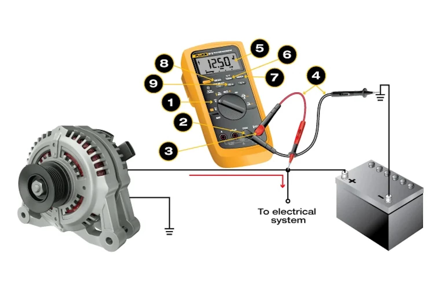
Figure 3: Proper Connection of Test Leads for Measuring DC Voltage with a Digital Multimeter
A DMM can measure both Direct Current (DC) and Alternating Current (AC) voltages. To measure DC voltage, insert the red test lead into the VΩ port and the black test lead into the COM port. For AC voltage, the process is the same, but the meter will automatically adjust to read AC signals, which change direction. Many modern DMMs have a feature that automatically detects the polarity of a DC circuit. This means you don't have to worry about connecting the leads to the correct positive or negative side—the meter will do it for you.
When measuring higher voltages, the DMM uses special internal circuits to lower the voltage to a level that its sensor can safely measure. If you are using a DMM that requires you to select the range manually, make sure to pick the right range for the voltage you're testing. If you choose a range that's too low, it could overload the device, leading to wrong readings or damage.
Current Measurements
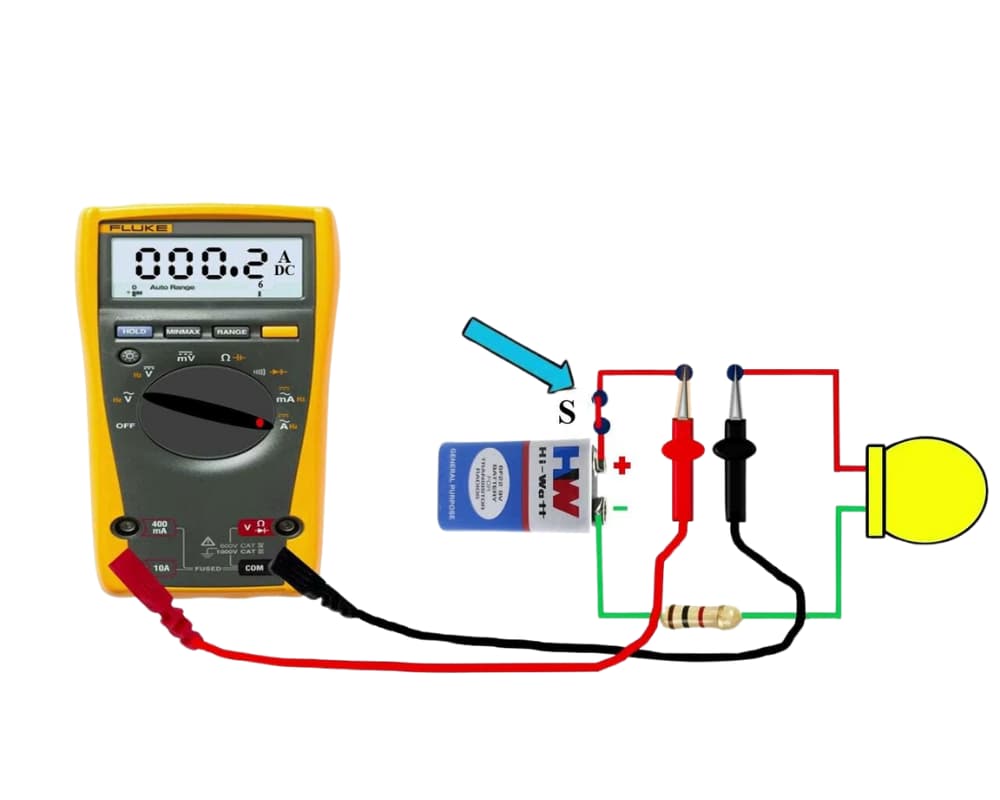
Figure 4: Proper Connection of a Digital Multimeter in Series to Measure Current
Measuring current with a DMM is a bit more complex than measuring voltage. To measure current, you have to break the circuit and connect the meter in series, meaning the current must flow through the DMM. The meter then checks the current by looking at the voltage drop across a built-in resistor.
This method of measuring current is riskier than voltage measurements because improper setup can damage the meter or blow its fuse. Most DMMs have fuses to protect them from too much current, but it's still a good idea to double-check that everything is set up correctly before taking a measurement. Always make sure the expected current is within the meter's limit, and don't leave the meter in current mode when switching to other tests. Forgetting to switch modes can easily blow a fuse when you try to measure something like voltage or resistance afterward.
Resistance Measurements
Resistance measurements with a DMM are quite easy. The meter sends a small amount of current through the resistor and checks the resulting voltage drop to calculate the resistance. Make sure the circuit is turned off and has no power before measuring resistance. If there’s still power in the circuit, you could damage the DMM or get an inaccurate reading.
When measuring resistance, the temperature of the resistor or the presence of other components in the circuit can affect the reading. For accurate results, it's often better to measure resistors separately, outside the circuit.
Continuity Testing
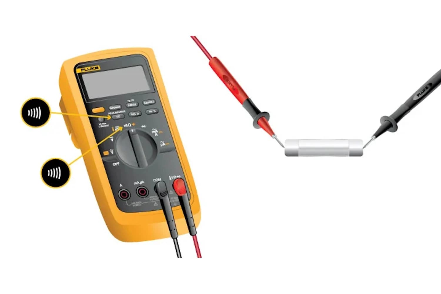
Figure 5: Performing a Continuity Test with a Digital Multimeter
Continuity testing is a quick way to see if a circuit or a component has an unbroken path for current to flow through. In this mode, the DMM makes a sound if the path is complete, which is called continuity. This feature is especially useful when checking things like fuses, switches, or wires, as you can hear the result instead of having to watch the display. The sound tells you immediately if the connection is good, helping you to find broken or faulty connections faster.
Diode Testing
In diode testing mode, the DMM applies a small voltage to the diode and checks how much voltage drops across it. A working diode usually shows a forward voltage between 0.5V and 0.7V, depending on its type. When testing a diode in reverse, the DMM should display an overload (OL), meaning no current flows through, which is normal for a properly working diode in reverse bias.
Diode testing is a better way to check if a diode works correctly than using a standard resistance check. It gives you more specific information about the diode's behavior when current flows in the forward direction.
Advanced Features of Digital Multimeters
Digital multimeters (DMMs) are useful tools for both professionals and hobbyists who work with electrical systems. Some DMMs come with advanced features that make them even more helpful for finding and fixing issues in electrical circuits. Here's a closer look at some of these features, explained in simpler language:
Auto-Ranging vs Manual-Ranging
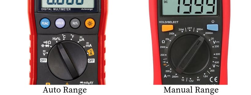
Figure 6: Auto-Ranging vs Manual-Ranging Digital Multimeter
One difference between digital multimeters is whether they are auto-ranging or manual-ranging. An auto-ranging DMM automatically chooses the correct range for measuring things like voltage, current, or resistance. This makes it easier to use since you don't need to know the exact value beforehand. It saves time and lowers the chance of mistakes, especially if you're unsure of what you're measuring. On the other hand, a manual-ranging DMM requires you to pick the range yourself. This gives you more control and is helpful if you already have an idea of what range to expect. It can also give you a better sense of what’s going on when the value you're measuring is higher or lower than expected.
True RMS Measurements
True RMS (Root Mean Square) measurements are useful when you're working with AC (alternating current) signals, especially when the signals aren't smooth. A True RMS DMM can accurately measure AC voltage or current, even when the signal is not a perfect wave, like a square or irregular-shaped wave. Regular DMMs that don’t have True RMS assume the signal is always a smooth wave, which can lead to errors—sometimes as much as 40% off. Using a True RMS meter helps you get correct readings when you're dealing with more complicated or uneven waveforms, which are common in modern electronic devices.
Peak Hold and Min/Max Functions
The peak hold feature captures the highest value a signal reaches while you’re measuring. This is useful for tracking fast, temporary surges in current, like the burst of current that happens when a device is first turned on. The min/max feature keeps track of the lowest and highest values during your measurement, so you can see how much a signal is changing over time. These features are helpful when you’re trying to monitor changes in a circuit, like drops in voltage or sudden increases in current, without having to constantly watch the display.
Data Hold and Relative Mode
The data hold function allows you to freeze the current reading on the display, which is useful when you’re in a situation where it’s hard to see the multimeter or keep track of what you're measuring. This way, you don’t lose a reading when it’s difficult to view the display. Relative mode lets you set a baseline value, so you can compare future readings to this reference point. This feature is especially helpful for spotting small differences, like slight changes in voltage or resistance, which can point to a problem or gradual wear in a part of the circuit.
Frequency and Capacitance Measurement
Some digital multimeters can also measure frequency and capacitance. Frequency is measured in Hertz (Hz) and is useful when checking circuits that run on alternating current, like motors or generators. Measuring frequency helps you figure out if the system is working at the right speed or if something is wrong. Capacitance is measured in farads (F) and is useful when working with capacitors, which store electrical energy. A capacitance measurement helps you check if a capacitor is still working properly or if it's worn out, which can affect how a circuit performs. Capacitors are found in many circuits and play an important role in regulating voltage or filtering signals.
Practical Use of a DMM
Multimeter Safety
Safety is very important when using a Digital Multimeter (DMM). Before using it, always check the Category (CAT) rating of the device. The International Electrotechnical Commission (IEC) has created four categories that describe the amount of electrical energy and voltage a DMM can handle without risking damage or injury:
• CAT I: Used for circuits with low energy, like those found in electronics or small devices.
• CAT II: This is for household devices or portable tools connected to standard electrical outlets, where the risk of higher voltages is lower, but still exists.
• CAT III: Designed for electrical systems inside buildings, such as wiring in walls, electrical panels, and industrial equipment. These systems are directly connected to the electrical distribution network and may experience voltage spikes.
• CAT IV: Covers areas with higher energy levels, such as overhead power lines or underground utility services, where electricity enters a building. These systems can have much stronger power surges than lower categories.
Using a DMM outside of its rated category is unsafe and could lead to injury or equipment damage, because the meter may not be able to handle higher energy levels than it was made for. Also, always check that the test leads are properly connected to the right input ports before making any measurements. Incorrect connections can lead to inaccurate readings or damage the meter.
Measuring Voltage and Current Safely
When measuring voltage, always connect the black (negative) lead to the ground or neutral wire first, and then connect the red (positive) lead to the live wire. This reduces the risk of shock because the meter is not connected to the live part of the circuit right away. If you're working with higher voltage, this method also helps keep you safer by reducing exposure to the live part of the circuit.
For measuring current, a clamp meter is often the best tool. A clamp meter measures current by detecting the magnetic field created by the flow of electricity in a wire. To get an accurate reading, make sure to clamp around just one wire—either the live or neutral wire. If you clamp around both the live and neutral wires at the same time, the reading will be zero because the magnetic fields from the two wires cancel each other out. To get a correct measurement, you need to measure one wire only.
Conclusion
Digital multimeters are useful tools for anyone working with electricity, helping you measure voltage, current, resistance, and other values with accuracy. By understanding the basic parts of the multimeter, like how it converts signals into numbers and how to read the display, you can make sure you're using it the right way. Whether you're testing to see if a circuit is working, measuring how much current is flowing, or using special features like True RMS (which gives more accurate readings for AC signals), learning to use a DMM will make your work easier and safer. With practice, you'll be able to confidently rely on your digital multimeter to handle both simple and more challenging electrical tasks.
Frequently Asked Questions [FAQ]
1. How does a digital current meter work?
A digital current meter measures the flow of electrical current in a circuit. It does this by detecting the small voltage drop across a resistor connected in the circuit. The meter takes this voltage signal, converts it into a number using electronic components, and then shows the result on a screen as the current reading.
2. What is the working principle of a digital multimeter?
A digital multimeter works by measuring different electrical values, such as voltage, current, or resistance, depending on the setting. It uses circuits inside to take these measurements, then changes them into numbers that can be shown on the screen. The user chooses the setting based on what they want to measure.
3. How is a digital multimeter used?
To use a digital multimeter, you first choose what you want to measure (voltage, current, or resistance) by turning the dial to the right setting. Then, you connect the test wires to the part of the circuit or device you want to check. Once connected, the meter will show the value of what you’re measuring on the screen. Make sure to select the correct setting and range to avoid mistakes or damaging the meter.
4. How accurate is a digital multimeter?
The accuracy of a digital multimeter depends on the model and quality. Many basic models give readings that are about 0.5% to 1% close to the actual value. More advanced models can give even more precise readings, sometimes as close as 0.01%. Always check the user manual to know the exact accuracy of your device.
5. How to use a digital multimeter to check voltage?
To check voltage with a digital multimeter, first turn the dial to the voltage setting (make sure to choose AC or DC, depending on what you’re measuring). Plug the black wire into the "COM" port and the red wire into the port labeled with a "V" for voltage. Then, touch the black wire to the negative point and the red wire to the positive point in the circuit. The multimeter will show the voltage on the screen. Make sure you handle the wires properly to avoid errors or short circuits.