The Ultimate Guide to Wire Color Codes in Modern Electrical Systems
The way our electrical systems use colors isn’t just for looks. Each wire color now indicates a specific function, making it easier to identify and handle electrical components correctly during installation and maintenance. This not only speeds up operational processes but also reduces the chances of mistakes and helping both users and technicians stay safe. This article explores the importance of wire color codes, their impact on safety and functionality, and the global standards that guide them. By looking at the history and details of these color codes, we highlight their key role in making electrical systems more efficient and safer.Catalog
Figure 1: Wire Colors
The Evolution of Wire Color Codes
As electrical systems got complex in the early twentieth century, the need for standardized wire colors became clear in order to avoid accidents and inefficiency. The introduction of standardized color codes in the United States during the 1920s initiated a global movement towards similar regulations. In 1928, the National Electrical Code (NEC), create a consistent framework for electrical installations. Before this regulation, electrical wiring was a mix of various colors and configurations, leading to confusion and hazardous situations. Without a uniform color code, even simple electrical tasks were dangerous and challenging. Over time, these codes have been refined through technological advancements and international collaboration, resulting in the sophisticated color-coding systems we use today. The continuous development of these standards demonstrates a strong commitment to safety and efficiency in the electrical field, highlighting how standardization can lead to significant improvements in both practice and protocol.
The National Electrical Code (NEC) Wire Color Codes
The National Electrical Code (NEC) provides a wire color-coding system for residential wiring to enhance safety and operational efficiency. This system assigns specific colors to different conductors, making it easier to identify them and reducing errors during electrical work.
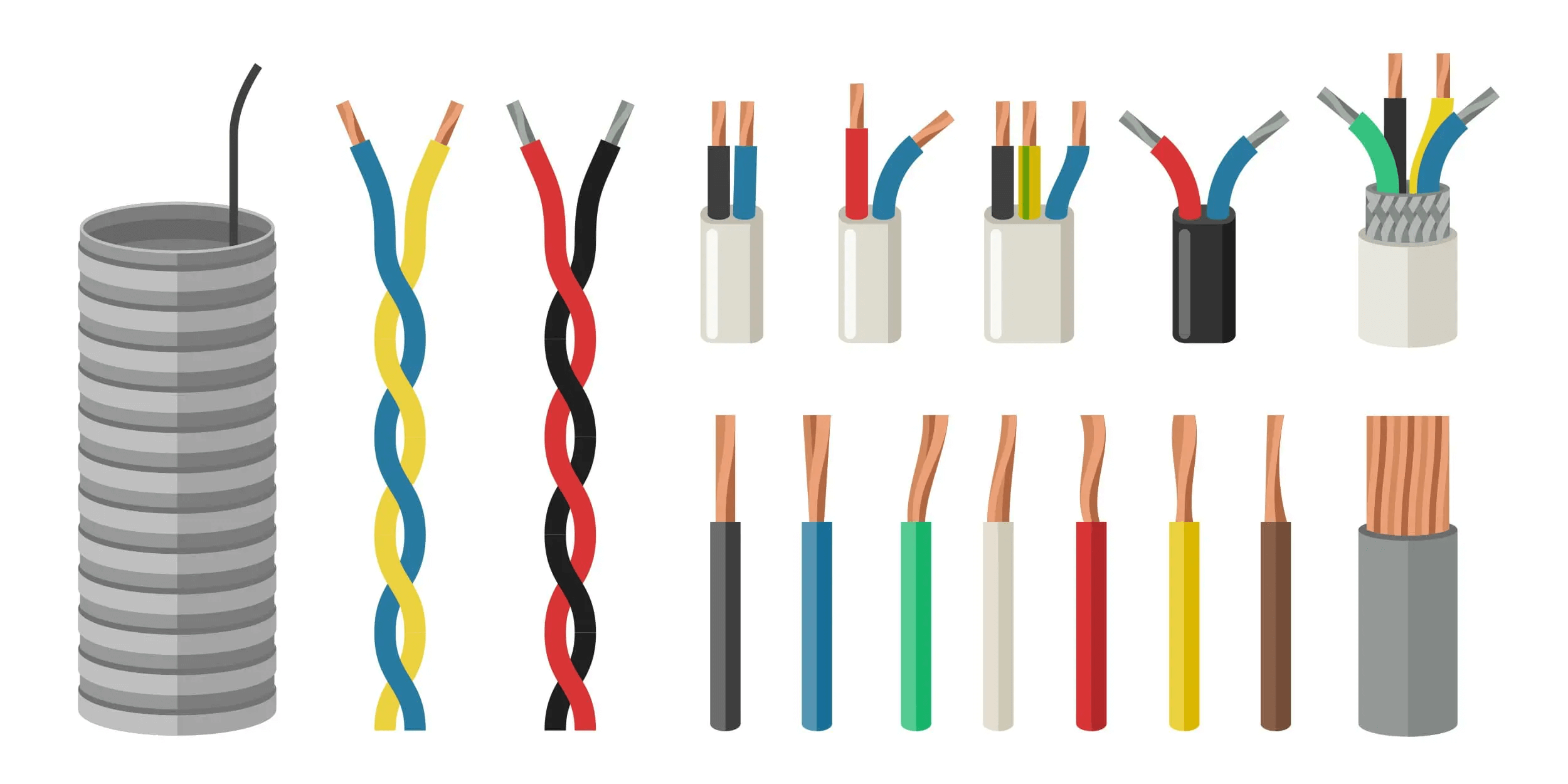
Figure 2: Wire Colors
• Hot Conductors
Hot conductors have red, black, or sometimes white insulation with red or black stripes. These wires carry electricity from the circuit breaker to outlets, fixtures, or switches. Identifying these active wires matters for electricians who do the initial circuit connections helps them make sure that everything is connected correctly and safely.
• Neutral Wires
Neutral wires are marked in white or gray. Their job is to return electrical current to the power supply after it has traveled through the hot wires. Using consistent colors for neutral wires helps electricians make safe and accurate connections to complete electrical circuits, ensuring devices and appliances work correctly.
• Ground Wires
Ground wires are either bare copper or coated in green insulation. They provide a safe path for electricity to be diverted into the earth in case of a fault, such as a short circuit. This prevents electric shocks and ensures overall safety.
• Traveler Wires
For three-way switches, the NEC specifies blue and yellow for traveler wires. These wires change their role depending on the switch position, allowing control of a single light from multiple locations. This color coding helps electricians manage wiring in complex switch setups, improving both functionality and safety.
Cable Sheathing Color Codes
The color of the outer sheathing on electrical cables is not just for looks; it indicates the wire gauge, its capacity, and suitable applications. This color-coding helps quickly identify a cable's characteristics, making selection and installation safer and more efficient.
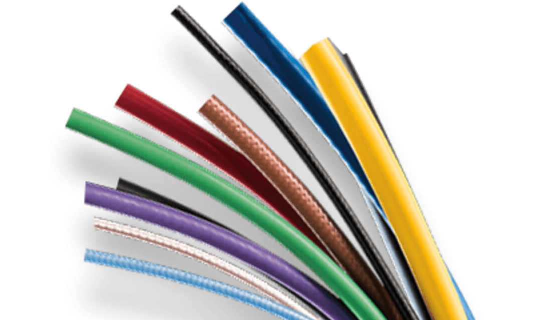
Figure 3: Cable Sheathing Color
• White Sheathing
White sheathing covers 14-gauge wires used in 15-amp circuits. These are standard for interior lighting and some receptacle circuits that do not need high amperage. White sheathing makes it easy to identify circuits that handle moderate loads, guiding electricians and DIY enthusiasts.
• Yellow Sheathing
Yellow sheathing indicates 12-gauge wires for 20-amp circuits. This wiring is common in kitchens and bathrooms, where ground fault circuit interrupter (GFCI) outlets are installed for appliances like blenders, hairdryers, and toasters. The yellow color ensures quick recognition, helping place wiring in areas with higher electrical demands.
• Orange Sheathing
Orange sheathing houses 10-gauge wires for 30-amp circuits. This gauge is used for larger appliances like air conditioners and washing machines that need more electrical power. The orange color quickly signals installers to the higher capacity, ensuring correct and safe installations.
• Black Sheathing
Black sheathing indicates cables that can handle between 40 and 60 amps. These are ideal for high-demand appliances and some industrial equipment. Black sheathed cables are designed to support substantial electrical loads, making them valuable in settings with intensive power requirements.
• Gray Sheathing
Gray sheathing is used for cables in outdoor or wet locations. These wires must survive dampness and exposure to the environment while remaining safe and working properly. When installing power supply lines in moist regions or installing external lights, gray sheathing is required.
Advantages of Color-Coded Wires
Enhanced Safety
Color coding in electrical wiring greatly enhances safety. Different wire colors serve as visual cues, helping to prevent misconnections and reduce electrical hazards. Electricians can quickly identify wire types, which is good for avoiding contact with live wires during installation or maintenance. This clear recognition of wire functions ensures safer working conditions and helps prevent serious electrical accidents. Strict adherence to these color codes must be maintained for everyone involved in electrical work.
Efficient Troubleshooting
Color coding makes troubleshooting much easier. It simplifies tasks such as adding new appliances or performing maintenance. Technicians can trace and identify wires by their color, which speeds up the diagnosis and repair of system faults. This efficiency reduces the time needed for repairs and minimizes downtime, allowing for quicker restoration of normal operations with minimal disruption.
Improved Collaboration and Communication
A universal color-coding system improves communication among electrical professionals. Standardized wire colors reduce misunderstandings and errors during installations and repairs. This shared understanding creates a more cohesive and efficient work environment, enhancing both safety and efficiency in electrical projects.
Empowerment of Non-Professionals
Understanding basic wire colors can benefit homeowners and non-professionals. This knowledge allows them to perform simple electrical tasks, such as replacing light fixtures or installing outlets, more confidently and safely. Familiarity with color codes can also save costs by reducing the need for professional help with minor adjustments and installations.
Regulatory Compliance and Safety Standards Adherence
Knowing wire color codes must be maintained for ensuring that changes or additions to electrical systems meet safety regulations. This knowledge is also helpful during inspections, enabling the identification and correction of potential issues or hazards. Adhering to these standards helps maintain the system’s safety and functionality, enhancing the durability and reliability of electrical installations.
Standardization Across Power Systems
Maintaining a safe and compliant electrical environment depends on following to color coding standards for both AC and DC circuits. This practice meets regulatory requirements and helps prevent electrical accidents. Standardization across power systems ensures a systematic approach that improves safety and facilitates efficient maintenance.
Electrical Wiring Color Code Standards
Maintaining the safety and effectiveness of electrical work requires an understanding of the color coding of electrical lines. Here’s a detailed look at each color code and its practical uses:
Black Wires
Electrical systems in homes and businesses both depend on black wires. They carry current from the power source to outlets, switches, and other points. These wires are always live, which means they can be dangerous if not handled correctly. Because they are used in many types of circuits, it’s very important to identify and handle them carefully to avoid accidents.
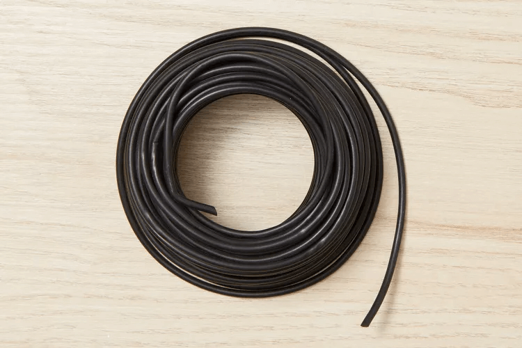
Figure 4: Black Wire
Red Wires
Red wires are used in specific setups. They carry power in 220-volt circuits for appliances that need a lot of power, like ovens and dryers. Red wires are also used in systems where smoke detectors are connected to each other for synchronized alarms. Red cables serve a purpose in homes for multi-way switches that allow you to control lights from multiple locations and makes the system more functional and safer.

Figure 5: Red Wire
Orange Wires
Red and orange wires are used where different voltage levels are needed. Red wires can handle both low and high energy demands, depending on the circuit. Orange wires are usually for higher voltages and good for safety and clarity in electrical systems. They are often used in switch legs and in connecting safety systems like smoke detectors.

Figure 6: Orange Wire
Blue and Yellow Wires
Blue and yellow wires are not commonly used in standard outlets. They are mostly found in systems that use conduits. Yellow wires are often used as switch legs for lighting, while blue wires are used in complex control setups in buildings. These wires have specific roles that help maintain the integrity of the system and prevent wiring errors in complex installations.
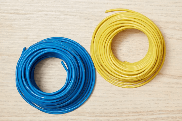
Figure 7: Blue and Yellow Wires
Blue Wire
In some cases, blue wires are used as neutral wires. They complete circuits by returning used electricity to the source. While they are generally safer, they can be dangerous in unbalanced or poorly managed circuits. This highlights the need for skilled installation and careful handling.
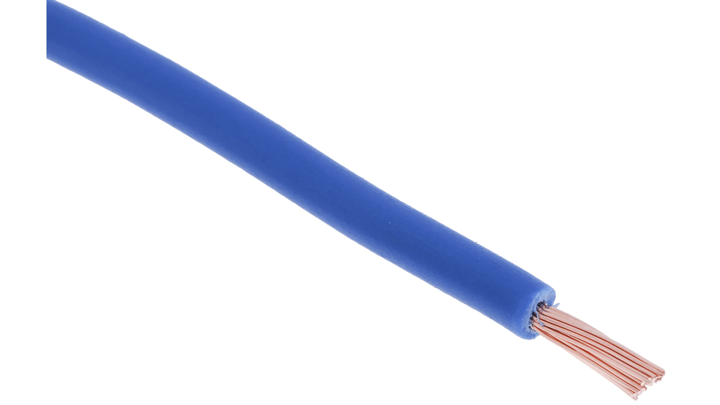
Figure 8: Blue Wire
White Wires with Red or Black Tape
Normally, white wires are neutral. But if they have red or black tape, they indicate that they are live. The flexible control of electrical flow that these lines enable helps in intricate configurations such as multi-way switches. For safe operation, it is imperative that these wires be identified correctly.
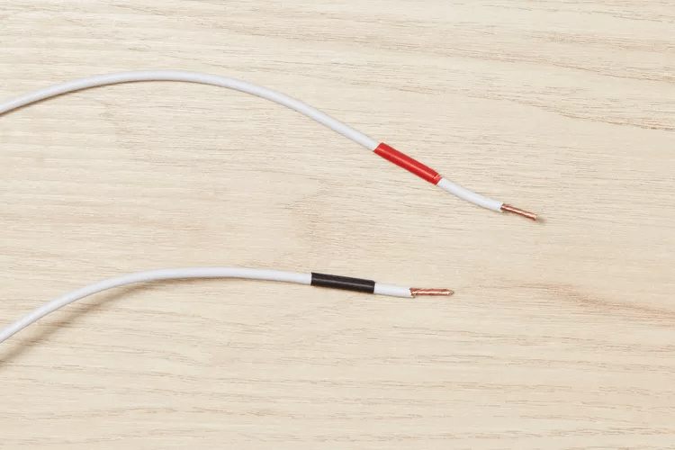
Figure 9: White wires with Red and Black Tape
Green Wires
Green wires provide a path to the ground. They divert excess or accidental electricity safely into the earth, connecting to grounding terminals. This helps protect the electrical system from faults and reduces the risk of electrical shocks or fires.

Figure 10: Green Wires
Green and Yellow Wires
Green wires with yellow stripes ground metal casings of devices, preventing electricity from directly transferring to users. This safeguards against shocks and highlights the importance of correct wiring practices.
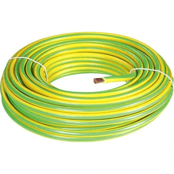
Figure 11: Green and Yellow Wires
Bare Copper Wires
Bare copper wires are key in grounding systems. In many installations, they offer an effective route for fault currents to return to the ground. Their widespread use underscores the importance of a well-implemented grounding system for safety.

Figure 12: Bare Copper Wire
White or Gray Wires
White and gray wires carry the return current back to the power source. They help balance circuits and ensure they work properly. However, if the circuit is unbalanced, these wires can be risky. This means they must be handled with care and a thorough understanding of the system.

Figure 13: White Wires
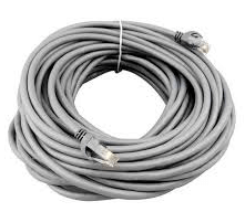
Figure 14: Gray Wires
Brown Wires
Brown wires carry power within circuits, just like other live wires. They pose electrocution risks and must be disconnected during maintenance to prevent accidents. Safe electrical operation relies on handling brown wires correctly.
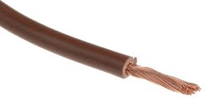
Figure 15: Brown Wire
Twenty-Five Pair Color Code
The 25-pair color code is used to identify individual wires in twisted-pair wiring for telecommunications. Each wire is marked with two colors: a major color and a minor color. The major color comes from a group of five colors: white, red, black, yellow, and violet. The minor color comes from another group of five: blue, orange, green, brown, and slate.
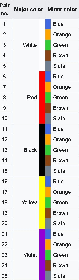
Figure 16: 25Pair color codes
Each wire has a background color with a tracer of the paired color. For example, pair 9 is red-brown. These color combinations help in identifying and organizing wires in telecommunications systems.
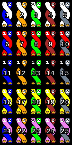
Figure 17: 25-pair color coding using twisted pairs with solid color coding only
Old Bell System wiring used a 4-conductor cable with solid red, green, yellow, and black wires. These match the 25-pair color code, helping in the transition and understanding of modern telecommunications wiring.
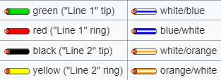
Figure 18: Old Bell System wiring
The 'C' Wire and Color Codes for Thermostats
The "C" wire, also known as the common wire, is usually blue but can sometimes be black. It provides continuous power to systems like thermostats, ensuring they work without interruptions. Before working with the "C" wire in thermostat installations or repairs, disconnect all power sources to prevent accidents. This safety step must be followed meticulously. Once the power is off, technicians use a multimeter to verify that there is no electric current in the wires before starting work. The multimeter also measures the voltage to ensure that the wiring and connections are correct for their intended use.
To identify and connect the "C" wire in thermostat systems, first, make sure the main power supply to the area where the thermostat is being installed or serviced is turned off. Next, use a multimeter to check that no current is flowing through the wires to prevent electrical shocks or accidents. Locate the "C" wire by its color, typically blue or sometimes black. If the wire is not immediately apparent, refer to the wiring schematic for the HVAC system or the thermostat manufacturer's guidelines.
Connect the "C" wire to the thermostat's designated terminal, usually marked 'C'. The thermostat needs this connection in order to run continuously. Once the "C" wire is connected, it’s advisable to use the multimeter again to ensure everything is correctly set up and functioning. This thorough testing ensures the operational efficiency of the thermostat and enhances the safety of the electrical system. Following these steps helps technicians ensure that the thermostat will work reliably, providing uninterrupted climate control.
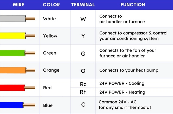
Figure 19: Common Thermostats Wire Colors
Three-Phase Wire Color Codes
In low-voltage distribution networks (typically 240V and 415V), the 3-phase four-wire system is common. This setup includes three live wires (L1, L2, L3) and a neutral (N). Unlike single-phase systems, where the neutral carries current to complete a circuit, in a three-phase system, the phases themselves form the circuit. The neutral line usually carries no current under normal conditions.
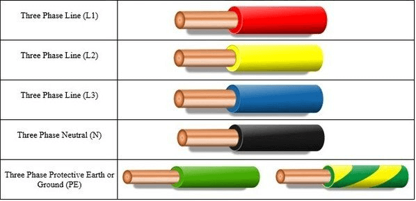
Figure 20: Color code of a three-phase wire
A 220V line voltage can be achieved using this design from a 380V phase voltage, which must be supplied for many applications. The neutral line also serves for zero-sequence current detection, need for monitoring the balance of the three-phase power supply and ensuring operational stability and safety. Three-phase power systems are need in commercial and industrial settings, driving heavy machinery efficiently and safely. These systems use a standardized color coding: black for Phase A, red for Phase B, and blue for Phase C. Proper installation and continuous maintenance depend heavily on this color scheme.
Before starting any work, technicians must identify each wire by its color to determine its corresponding phase. Avoiding cross-connecting phases, which may result in electrical problems or damage to equipment, is a must. When connecting wires, electricians ensure that each color aligns with its respective terminal. The black wire, representing Phase A, connects to terminal A or 1. The red wire, representing Phase B, connects to terminal B or 2. The blue wire, representing Phase C, connects to terminal C or 3. This methodical approach prevents misconnections and potential operational failures. After making the connections, electricians use phase testers and multimeters to verify that each phase is correctly connected and operating safely. This step confirms that the equipment will run reliably without electrical mishaps.
Clear color coding helps in troubleshooting. If an issue arises, technicians can quickly identify and assess the specific phase involved, making it easier to diagnose and fix problems. This efficient problem-solving save time and reduces downtime in industrial operations. Regular maintenance checks include verifying the integrity of the color-coded wiring. Electricians check for signs of wear, insulation damage, or color fading, which can affect safety and functionality. Maintaining system dependability requires precise and clear color coding.
Alternating Current Power Wiring Color Code Standards
AC (Alternating Current) power wiring uses specific color codes based on national or regional electrical standards. These color codes ensure consistency and safety in electrical installations, helping electricians and technicians identify and connect wires correctly.
Residential and Commercial AC Power Color Codes
In homes and offices, AC power systems usually operate at 120, 208, or 240 volts. The following color codes are commonly used:
|
Phase |
Wire Color |
|
Phase 1 |
Black wire |
|
Phase 2 |
Red wire |
|
Phase 3 |
Blue wire (specifically in 208V systems) |
|
Neutral |
White wire |
|
Ground |
Green, green with a yellow stripe, or bare wire |
During installation, electricians use these color codes to connect electrical appliances and outlets properly. Phase wires (black, red, and blue) are connected to their respective circuit breakers, ensuring the distribution panel routes power effectively.
For maintenance or repair, technicians quickly identify each wire's purpose. This allows for safe checks and fixes without disrupting the system’s integrity. Testing involves checking voltage levels between phases and between phase and neutral. This ensures the voltage matches expected values, confirming the system's correct setup.
Industrial AC Power Color Codes
In industrial settings with higher voltages (277 or 480 volts) for powering heavy machinery, the color codes differ:
|
Phase |
Wire Color |
|
Phase 1 |
Brown wire |
|
Phase 2 |
Orange wire |
|
Phase 3 |
Yellow wire |
|
Neutral |
Gray wire |
|
Ground |
Green, green with a yellow stripe, or bare wire |
Identify each wire by color to determine its corresponding phase. This prevents cross-connecting phases, which can cause electrical faults or equipment damage.
Connect wires so that each color aligns with its respective terminal. For example, black wire (Phase 1) to terminal 1, red wire (Phase 2) to terminal 2, and blue wire (Phase 3) to terminal 3. This prevents misconnections and operational failures. After connections are made, use phase testers and multimeters to verify correct and safe operation. This confirms that the system runs reliably without electrical mishaps.
Clear color coding helps in troubleshooting. If an issue arises, technicians can quickly identify and assess the specific phase involved, making it easier to diagnose and fix problems. Regularly check the integrity of color-coded wiring. Look for signs of wear, insulation damage, or color fading. For a system to remain reliable over time, color coding must be accurate and clear.
Direct Current Power Wiring Color Code Standards
DC (Direct Current) power systems use specific color codes to identify different conductors, enhancing safety, consistency, and efficiency in wiring installations and maintenance. These color codes are desired for the proper identification and connection of wires in DC power circuits.
|
DC Power Wiring |
Color Code |
|
Positive |
Red wire |
|
Negative |
Black wire |
|
Ground |
White or gray wire |
Due to the variability in wiring color standards, electricians and technicians must follow careful practices when dealing with DC wiring. They should visually identify wire colors according to the system’s documentation or standards. The real polarity and voltage of wires must always be confirmed with a voltmeter, as assumptions made solely on the basis of color can result in errors because proper procedures aren't followed. When connecting wires, ensure they are matched according to their verified polarity, particularly in systems like automotive electrical frameworks or industrial control panels.
DC power is primarily used in applications requiring stable and precise voltage control. For instance, tramway systems typically operate at around 600V, while railway DC traction systems may use 1.5 kV between the rail and overhead collector wire. Industrial machinery such as lifts, printing presses, and various other machines that need smooth speed control often rely on DC power. Electroplating and battery charging processes also use DC for its ability to provide consistent voltage and current.
DC systems are generally configured as either 2-wire or 3-wire setups. A 2-wire system includes one positive and one negative terminal, while a 3-wire system incorporates an additional ground or neutral line for safety and stability in higher power applications. Maintaining system integrity and safety requires strict attention to operational procedures and color coding. Proper management of DC wiring prevents operational failures, ensures the safety of technicians, and enhances the overall reliability of the power system.
Electrical Wiring Color Code by Country/Region
To securely manage electrical systems, one must be aware of the color codes for electrical wiring, which can vary depending on the country or region. Maintaining the safety and features of the electricity system requires an understanding of local standards. Professionals may assist ensure electrical systems are safe, dependable, and efficient by adhering to these regional color standards, which reduces risks and improves overall performance.
• United States
In the U.S., color standards are required for identifying wire functions within various electrical systems. Typical residential and commercial setups (120/240V systems) use:
|
Setting |
Wire Function |
Color(s) |
|
Residential Systems |
Hot wires |
Black, red |
|
Neutral |
White |
|
|
Ground |
Green or bare copper |
|
|
Commercial Systems (120/208V) |
Hot wires |
Black, red, blue |
|
Neutral |
White |
|
|
Ground |
Green or bare copper |
|
|
Industrial Applications (277/480V) |
Hot wires |
Brown, orange or purple, yellow |
|
Neutral |
Gray |
|
|
Ground |
Green or bare copper |
• Canada
Canada's standards are similar to those in the U.S. but occasionally use red or blue for hot wires in specific configurations. For DC voltage setups:
|
Application Type |
Wire Function |
Color(s) |
|
Standard |
Hot wires |
Black, red, blue |
|
|
Neutral |
White |
|
|
Ground |
Green or bare copper |
|
DC Voltage Setups |
Positive |
Red |
|
|
Negative |
Black |
|
|
Ground |
White |
• United Kingdom
|
Wire Function |
Color(s) |
|
Hot |
Brown |
|
Neutral |
Blue |
|
Ground |
Green with yellow stripes |
European standards follow the International Electrotechnical Commission (IEC).
• Germany
Uses the same color scheme as the UK, emphasizing uniformity across the continent. These standards help ensure consistency and safety across installations, simplifying the work for electrical professionals and reducing the likelihood of errors.
• China
|
Wire Function |
Color(s) |
|
Hot |
Red |
|
Neutral |
Black |
|
Ground |
Green |
• Japan
|
Wire Function |
Color(s) |
|
Hot |
Brown |
|
Neutral |
Blue |
|
Ground |
Yellow with green stripes |
How to Check and Maintain the Safety of Electrical Wiring?
Identifying Potential Risks: Regularly check for unusual odors or visible signs of damage, like burn marks around electrical outlets or appliances. These signs often indicate significant problems, such as short circuits or degraded wire insulation. If you notice these indicators, take immediate action to address the risks.
Assessing Wire Condition: Examine the wires behind sockets and switches to ensure they are in good condition and not deteriorating. Worn or frayed wiring can lead to electrical hazards if not promptly addressed. Look for signs of wear and tear, and replace any damaged wiring as necessary.
Addressing Circuit Overload: Modern appliances often require more power than older wiring systems can handle. This can lead to overloaded circuits, especially when multiple high-power devices are connected to a single outlet through a power strip. Overloading increases the risk of overheating and electrical fires.
To prevent overloading, use power cables rated for higher loads. You may also need to install additional power outlets or upgrade the existing wiring system to meet current and future electrical demands. These proactive steps not only prevent immediate risks but also enhance the long-term functionality and safety of the electrical infrastructure.
Conclusion
In summary, using wire color codes is more than just following rules. It is a key to making electrical systems safe, efficient, and reliable. These color codes help electricians work safely and ensure electrical setups work well. Different colors indicate phases, grounds, and neutrals, and they help manage complex circuits. As technology advances, sticking to these color codes will continue to improve electrical practices and keep power systems running smoothly worldwide. Maintaining the efficiency and safety of contemporary electrical systems involves an understanding of and adherence to these color standards.
Frequently Asked Questions [FAQ]
1. What are the common wire colors?
In electrical systems, different colors are used to prevent wiring errors and ensure a universal understanding of a wire's function. Commonly, the live (or hot) wire is black or red, the neutral wire is white or gray, and the ground wire is green or green with a yellow stripe. However, color coding can vary slightly depending on the country and the type of installation.
2. How to identify electrical wires?
Identifying electrical wires correctly is important for safety and effectiveness in any electrical installation or maintenance. Typically, this identification involves recognizing the wire colors, which indicate their purpose in the circuit. To accurately identify wires, you can use a voltage tester or multimeter to confirm if a wire is live, neutral, or ground. Also, examining the wiring diagram or installation manual of your specific setup can provide additional guidance.
3. Why live wire is red?
In many electrical systems, especially in older or more traditional setups, a red wire indicates a live wire. This color was chosen because it is bright and distinct, making it easily recognizable as a hazard (indicating it carries power). Red warns the user to be cautious and aware of the potential danger of touching this wire when live.
4. Is black and red wiring safe?
Black and red wires are commonly used to denote live wires in different phases of an electrical system. Using both colors in a single circuit is safe as long as they are properly installed and insulated. It is needed that both wires, along with others, are connected following the electrical codes and standards, ensuring that all connections are secure and covered to prevent accidental contact.
5. What color is neutral?
Typically, the neutral wire is colored white or gray. This color coding helps in distinguishing it from the live wire and the ground wire, reducing the risk of electrical shocks and ensuring safer handling during electrical works. Neutral wires carry the circuit's current back to the power source and are an important component of the electrical system.
About us
ALLELCO LIMITED
Read more
Quick inquiry
Please send an inquiry, we will respond immediately.
Resistance in Electrical Circuits
on June 12th
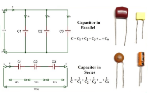
The Capacitor Guide: Series Vs. Parallel Configurations
on June 11th
Popular Posts
-

What is GND in the circuit?
on January 1th 2937
-

RJ-45 Connector Guide: RJ-45 Connector Color Codes, Wiring Schemes, R-J45 Applications, RJ-45 Datasheets
on January 1th 2501
-

Fiber Connector Types: SC Vs LC And LC Vs MTP
on January 1th 2089
-

Understanding Power Supply Voltages in Electronics VCC, VDD, VEE, VSS, and GND
on November 9th 1891
-

Comparison Between DB9 and RS232
on January 1th 1762
-

What Is An LR44 Battery?
Electricity, that ubiquitous force, quietly permeates every aspect of our daily lives, from trivial gadgets to life-threatening medical equipment, it plays a silent role. However, truly grasping this energy, especially how to store and efficiently output it, is no easy task. It is against this background that this article will focus on a type of coin cell battery that may seem insignificant on the...on January 1th 1713
-

Understanding the Fundamentals:Inductance Resistance, andCapacitance
In the intricate dance of electrical engineering, a trio of fundamental elements takes center stage: inductance, resistance, and capacitance. Each bears unique traits that dictate the dynamic rhythms of electronic circuits. Here, we embark on a journey to decipher the complexities of these components, to uncover their distinct roles and practical uses within the vast electrical orchestra. Inductan...on January 1th 1655
-

CR2430 Battery Comprehensive Guide: Specifications, Applications and Comparison to CR2032 Batteries
What is CR2430 battery ?Benefits of CR2430 BatteriesNormCR2430 Battery ApplicationsCR2430 EquivalentCR2430 VS CR2032Battery CR2430 SizeWhat to look for when buying the CR2430 and equivalentsData Sheet PDFFrequently Asked Questions Batteries are the heart of small electronic devices. Among the many types available, coin cells play a crucial role, commonly found in calculators, remote controls, and ...on January 1th 1552
-

What Is RF and Why Do We Use It?
Radio Frequency (RF) technology is a key part of modern wireless communication, enabling data transmission over long distances without physical connections. This article delves into the basics of RF, explaining how electromagnetic radiation (EMR) makes RF communication possible. We will explore the principles of EMR, the creation and control of RF signals, and their wide-ranging uses. The article ...on January 1th 1538
-

CR2450 vs CR2032: Can The Battery Be Used Instead?
Lithium manganese batteries do have some similarities with other lithium batteries. High energy density and long service life are the characteristics they have in common. This kind of battery has won the trust and favor of many consumers because of its unique safety. Expensive tech gadgets? Small appliances in our homes? Look around and you'll see them everywhere. Among these many lithium-manganes...on January 1th 1512
HOT Part Number
-

TPS259230DRCR
Texas Instruments
IC ELECTRONIC FUSE 8% 10VSON
LT6703HVIS5-3#TRMPBF
Analog Devices Inc.
IC COMPARATR 1 W/VOLT REF TSOT23
FMB2227A
onsemi
TRANS NPN/PNP 30V 0.5A 6SSOT
FQU5N60CTU
Fairchild Semiconductor
POWER FIELD-EFFECT TRANSISTOR, 2
FDMF6707V
Fairchild Semiconductor
IC HALF BRIDGE DRIVER 45A 40PQFN
DS75176BN
Texas Instruments
IC TRANSCEIVER HALF 1/1 8DIP
TLV2442IPWR
Texas Instruments
IC CMOS 2 CIRCUIT 8TSSOP
EPM3256ATC144-7
Intel
IC CPLD 256MC 7.5NS 144TQFP
GRM2165C1H1R0CD01J
Murata Electronics
CAP CER 1PF 50V C0G/NP0 0805
AD7805BR
Analog Devices Inc.
IC DAC 10BIT V-OUT 28SOIC
UC2843AQD8RQ1
Texas Instruments
IC REG CTRLR MULT TOPOLOGY 8SOIC
CL21B102KECSFNC
Samsung Electro-Mechanics
CAP CER 1000PF 250V X7R 0805
DB106S
Rectron USA
BRIDGE RECT 800V 1A DB-S
CL31C6R8CBCNNNC
Samsung Electro-Mechanics
CAP CER 6.8PF 50V C0G/NP0 1206
PAH150S48-5/PV
TDK-Lambda Americas Inc
DC DC CONVERTER 5V 150W
DBTC-9-4L+
Mini-Circuits
RF DIR COUPLER 5MHZ-1GHZ 5SMD
TLVH431BCPK
Texas Instruments
IC VREF SHUNT ADJ 0.5% SOT89-3
PI6C2408-1LIE
Diodes Incorporated
IC ZD BUFFER 16TSSOP -

FAN2512S33X
onsemi
IC REG LINEAR 3.3V 150MA SOT23-5
PAH300S48-12/T
TDK-Lambda Americas Inc
DC DC CONVERTER 12V 300W
TPS62260DDCTG4
Texas Instruments
IC REG BUCK ADJ 600MA SOT23-5
SN54LS03J
Texas Instruments
54LS03 QUADRUPLE 2-INPUT POSITIV
ISL1533IVEZ
Intersil
IC DRIVER 2/0 20HTSSOP
MAX5033AUSA+T
Analog Devices Inc./Maxim Integrated
IC REG BUCK 3.3V 500MA 8SOIC
MOC3020
Lite-On Inc.
OPTOISOLATOR 5KV TRIAC 6DIP
NCP511SN33T1
onsemi
IC REG LINEAR 3.3V 150MA 5TSOP
N7000050FBBAAA
Harris Corporation
N7000050FBBAAA
AOI518
Alpha & Omega Semiconductor Inc.
MOSFET N-CH 30V 18A/46A TO251A
MP6231DH-LF-Z
Monolithic Power Systems Inc.
IC PWR SWITCH 1:2 8MSOP
74438323082
Würth Elektronik
FIXED IND 8.2UH 700MA 743MOHM SM
BC556BTA
onsemi
TRANS PNP 65V 0.1A TO92-3
2N688A
Central Semiconductor Corp
SCR 400V 25A TO48
ADA4505-1ACBZ-R7
Analog Devices Inc.
IC OPAMP VFB 1 CIRCUIT 6WLCSP
SE555JG
Texas Instruments
PRECISION TIMER 8-CDIP -55 TO 12
EL7566AIREZ
Elantec
SWITCHING REGULATOR
145152
Brady Corporation
B302 10X14 ANSI RED,BLK/WHT HYDR -

GRM1555C1H5R3WA01D
Murata Electronics
CAP CER 5.3PF 50V C0G/NP0 0402
TLZ2V4A-GS08
Vishay General Semiconductor - Diodes Division
DIODE ZENER 2.4V 500MW SOD80
STGB7H60DF
STMicroelectronics
IGBT 600V 14A 88W D2PAK
CL10C3R3BB8NNND
Samsung Electro-Mechanics
CAP CER 3.3PF 50V NP0 0603
SWPA3012S4R7MT
Shenzhen Sunlord Electronics Co., Ltd.
FIXED IND 4.7UH 1.24A 156MOHM SM
CAT803TSDI-GT3
onsemi
IC SUPERVISOR 1 CHANNEL SC70
GRM0335C1H560JA01J
Murata Electronics
CAP CER 56PF 50V C0G/NP0 0201
85HQ040
Microchip Technology
DIODE SCHOTTKY 40V 80A DO5
SC2608BSTRT
Semtech Corporation
IC REG CTRLR BUCK 8SOIC
MM5Z10
Diotec Semiconductor
ZENERDIODE,SOD-523,10V,0.3W,5%
FDG901D
onsemi
IC DRIVER 1/0 SC70-5
UPD5716GR-E1-A
CEL
IC RF SWITCH 2.15GHZ 16HTSSOP
SN74F245DW
Texas Instruments
IC TXRX NON-INVERT 5.5V 20SOIC
MAX664CPA
Analog Devices Inc./Maxim Integrated
IC REG LIN NEG ADJ 40MA 8DIP
SN74AHC240PWR
Texas Instruments
IC BUFFER INVERT 5.5V 20TSSOP
IRFP460PBF
Vishay Siliconix
MOSFET N-CH 500V 20A TO247-3
LQP03TG4N7H02D
Murata Electronics
FIXED IND 4.7NH 250MA 720MOHM SM
BU4809FVE-TR
Rohm Semiconductor
IC SUPERVISOR 1 CHANNEL 5VSOF