The Capacitor Guide: Series Vs. Parallel Configurations
In electrical engineering, capacitors show many uses, especially when arranged in series or parallel in circuits. These arrangements affect the capacitance, energy storage, and efficiency of electrical systems. This article looks at how capacitors work in series and parallel setups, using examples and theory to explain their differences. It aims to provide a clear understanding of how to use capacitors effectively in various technologies, from everyday electronics to advanced industrial machines.Catalog
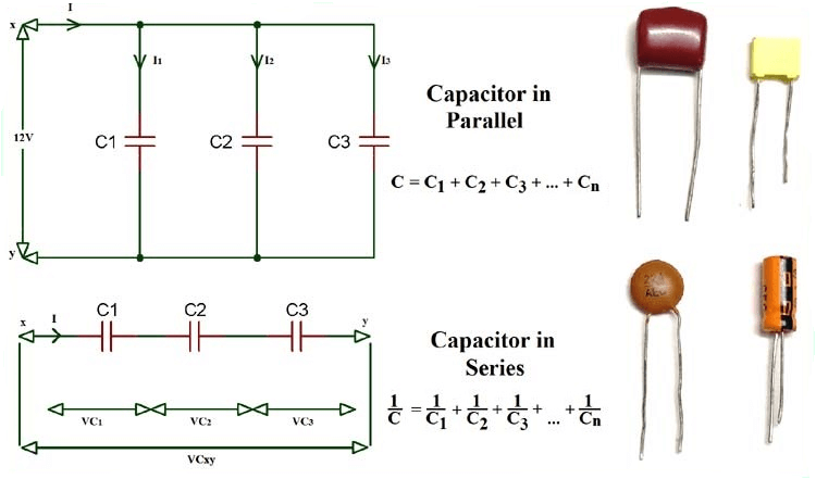
Figure 1: Capacitor Circuit
Capacitors in Electrical Circuits
In electrical circuits, capacitors serve a purpose for both storing and discharging electrical charge. They have two conductive plates separated by an insulating dielectric. Their ability to hold charge is measured in farads.
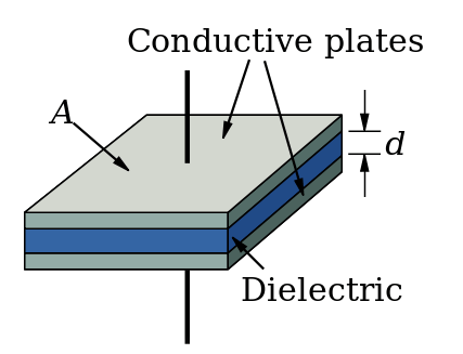
Figure 2: Capacitor
Capacitors can be connected in series or parallel. In series, more capacitors reduce overall capacitance, useful for achieving lower capacitance. In parallel, more capacitors increase total capacitance, ideal for high capacitance in small spaces, such as power supply filters. The dielectric material affects a capacitor's performance, determining maximum charge, breakdown voltage, and circuit frequency response. Advanced capacitors use materials like ceramic, tantalum, or polymer electrolytes for higher capacitance, temperature stability, and low leakage.
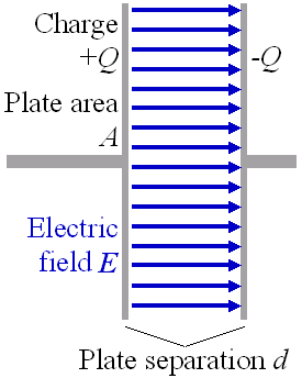
Figure 3: Capacitor
Properties of Capacitors in Series and Parallel
Here's a simple explanation of their properties and how these configurations can be arranged to get the desired capacitance.
Capacitors in Series
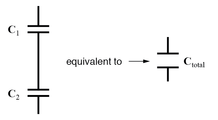
Figure 4: Capacitance Series
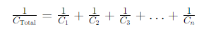
When you connect capacitors in series, the overall capacitance gets smaller. This happens because the charge has to travel through more material, making it harder to store charge. The total capacitance (1/Ctotal) is the sum of the reciprocals of each individual capacitor (1/C1 + 1/C2 + ... + 1/Cn). The overall capacitance is always less than the smallest capacitor in the series. The formula for calculating total capacitance in series is:
Circuit designers must take this feature into account when choosing capacitors to meet specific capacitance requirements. Practical constraints such as space and application needs can limit the number of capacitors in series, and varying voltage distributions can add complexity unless capacitors are identical.
Capacitors in Parallel
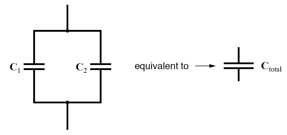
Figure 5: Capacitance Parallel
When capacitors are connected in parallel, the total capacitance increases. This is because the combined surface area of all the capacitors allows more charge to be stored at the same voltage. The total capacitance (Ctotal) is the sum of the capacitances of each capacitor (C1 + C2 + ... + Cn). The overall capacitance will be greater than the largest single capacitor. The formula for calculating total capacitance in parallel is:
Although, an unlimited number of capacitors can be connected in parallel, practical limitations like physical space, circuit purpose, and design constraints often limit the number. High-quality capacitors with appropriate voltage ratings and tolerances are good for reliable circuit performance. This formula allows precise control over capacitance values, enabling designers to optimize circuit behavior, energy efficiency, and performance, making it a cornerstone of electronics and electrical engineering.
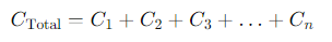
Figure 6: Series and Parallel
Series Capacitor Circuit and Example
A series capacitor circuit features capacitors linked sequentially along the same path, ensuring that identical charges or currents traverse through each component. It guarantees uniform current flow across the capacitors, a fundamental aspect for understanding the behavior of such circuits.
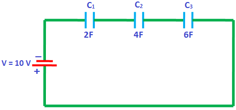
Figure 7: Series capacitor circuit
In a series setup, each capacitor must handle the same charge. When a DC voltage source is applied, the series connection dictates that charges redistribute along the capacitors to maintain this equilibrium. For instance, if a voltage source is connected across capacitors C1, C2, and C3 with values 2F, 4F, and 6F respectively, the following occurs:
• The right side of C3 becomes positively charged due to the attraction of electrons towards the positive terminal of the battery.
• This deficit of electrons on C3's right plate induces a similar deficit on C2's right plate, and sequentially the same effect occurs on C1.
• This chain reaction across the capacitors ensures uniform charge distribution.
Example:
Given the capacitances C1=2F, C2=4F, C3=6F and a DC voltage of 10V, we can determine the charge and voltage distribution:

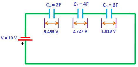
Figure 8: Sample Series
Calculating Ctotal yields approximately 0.92F.
Using Q=C×V, where Q is the charge and V is the voltage:
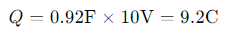
Thus, each capacitor holds a charge of 9.2C.
Voltage across each capacitor is found using V=CQ:
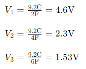
The sum of individual voltages, V1+V2+V3, should equal the source voltage (10V). Here, it computes to approximately 8.43V, indicating a possible rounding or calculation error in our initial estimations or assumptions.
Parallel Capacitor Circuit and Example
A parallel capacitor circuit is an electronic setup where capacitors are connected side-by-side across common points, allowing each to operate independently under the same voltage. This is different from series circuits, where capacitors share a charge.
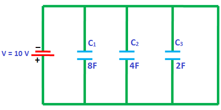
Figure 9: Parallel Capacitor Circuit
In a parallel, the voltage across each capacitor is the same. However, the charge each capacitor stores varies based on its capacitance. A higher capacitance means a capacitor can store more charge. For example, if we have capacitors of 8 farads (F) and 4F, the 8F capacitor will store more charge than the 4F capacitor when both are under the same voltage.
One key advantage of parallel capacitors is the increase in overall capacitance. Unlike series circuits, where the total capacitance is less than any individual capacitor, in parallel, the total capacitance is the sum of all individual capacitances. This happens because the plate area effectively increases without changing the distance between them, enhancing the circuit's ability to store charge.
Example:
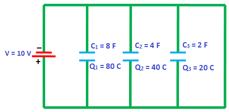
Figure 10: Sample Parallel
Consider a circuit with three capacitors connected in parallel to a 10V DC power source. The capacitors have these capacitances: C1 = 8F, C2 = 4F, and C3 = 2F. Each capacitor experiences the same 10V, but stores different charges based on their capacitance:
Capacitor C1: With 8F, it stores a charge of 80 coulombs (C), calculated as Q = C × V, which is 8F × 10V = 80C.
Capacitor C2: With 4F, it stores a charge of 40C, calculated as 4F × 10V = 40C.
Capacitor C3: With 2F, it stores a charge of 20C, calculated as 2F × 10V = 20C.
The total charge in the circuit is the sum of all the charges:QT = Q1 + Q2 + Q3 = 80C + 40C + 20C = 140C
This addition shows how a parallel capacitor circuit enhances charge storage by combining the capacitance of individual capacitors. A parallel capacitor circuit increases total capacitance and charge storage capacity, with each capacitor experiencing the same voltage.
Energy Stored in Capacitors in Series and Parallel
To understand how energy is stored in capacitors arranged in series or parallel, we start with the basic formula for the energy stored in a single capacitor:
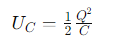
Here, UC is the energy in joules, Q is the charge in coulombs, and C is the capacitance in farads.
Energy in Series Capacitors
For capacitors in series, consider two capacitors with capacitances C1 and C2. The relationship between charge and voltage for each capacitor is given by C=VQ. In a series configuration, the same charge Q is on each capacitor:

The total energy stored in the system is the sum of the individual energies:
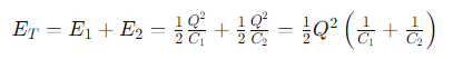
This shows that the effective capacitance of series capacitors is the reciprocal sum of the individual capacitances, which decreases the total capacitance and changes the energy storage compared to single or parallel configurations.
Energy in Parallel Capacitors
For capacitors in parallel, each capacitor has the same voltage across it. The energy for each can be expressed using the voltage-based formula:
If two capacitors C1 and C2 are in parallel and have the same voltage V across them, their total energy storage is:

This calculation shows that the total capacitance for parallel capacitors is the sum of the individual capacitances, which increases the total energy stored compared to individual or series configurations.
Advantages and Disadvantages of Capacitors in Series
Using capacitors in series offers some advantages, including an increased overall working voltage. This configuration also allows for more effective voltage balancing, especially when high-value resistors (around 100kΩ or higher) are placed across each capacitor to ensure a more even distribution of voltage.
Using capacitors in series comes with disadvantages, including the issue of unequal voltage sharing. Variations in leakage currents, particularly in electrolytic capacitors, can result in one capacitor experiencing over-voltage, which may lead to damage. Minor differences in manufacturing or aging rates also contribute to variations in leakage current, affecting voltage distribution. The leakage current in electrolytic capacitors tends to increase over time, especially if they are not regularly used. Even with balancing resistors in place, it is need to leave a margin in the working voltage, particularly for electrolytic capacitors, to ensure reliable operation.
Advantages and Disadvantages of Capacitors in Parallel
Increased Energy Storage: Connecting capacitors in parallel stores more energy than when they are in series because their total capacitance is the sum of all individual capacitors.
Better Voltage Balance: Parallel capacitor banks achieve better voltage balance with fewer balancing resistors, reducing costs and power losses.
Cost Efficiency: Fewer balancing resistors in parallel connections save money and simplify the system.
Voltage Limitation: In a parallel circuit, all capacitors share the same voltage. The maximum voltage is limited by the lowest-rated capacitor. For instance, if one capacitor is rated at 200V and others at 500V, the whole system can only handle 200V.
Safety Risks: Parallel capacitors store and release large amounts of energy quickly, which can be dangerous if there's a short circuit, potentially causing severe damage and injuries.
System Failure Risk: In complex layouts, if one capacitor fails, the others must handle the full voltage, leading to potential failure of the entire system. This risk is lower in series connections where one capacitor's failure doesn't affect the others.
Conclusion
This detailed look at capacitors helps us understand their functions and the important considerations for their use in modern electronics. Series setups increase working voltage and manage voltage distribution but reduce capacitance and increase sensitivity to variations. Parallel setups boost total capacitance and energy storage, which is good for energy management in small spaces, but they can be risky if one capacitor fails. Choosing between series and parallel configurations depends on specific engineering needs, balancing space, cost, and performance. The theoretical and practical insights emphasize careful capacitor selection and circuit design to ensure reliable and efficient electrical systems.
Frequently Asked Questions [FAQ]
1. What is the Effect of a Series Capacitor?
Series capacitors are used primarily to reduce the impedance of a circuit at higher frequencies, which improves power transmission over long distances and enhances voltage regulation. When capacitors are connected in series, the total capacitance decreases. This configuration forces the same charge to pass through all capacitors, resulting in a division of the total voltage across each capacitor according to its capacitance value. This characteristic is particularly useful in applications like signal coupling and filtering, where the goal is to block direct current (DC) while allowing alternating current (AC) to pass.
2. When to Use Series Capacitors?
Series capacitors are utilized when there is a need to adjust the impedance of a circuit, particularly in high-frequency applications. They are also employed to achieve voltage division in a circuit. In power systems, series capacitors are used to increase the capacity of power transmission lines by compensating for inductive reactance in long transmission lines, thus allowing more current to flow under the same voltage conditions.
3. How Do You Know if Two Capacitors are in Series?
Two capacitors are in series if they are connected end-to-end, with the positive terminal of one connected to the negative terminal of the other, and there are only two points of connection involving other circuit components. This arrangement ensures that the charge and discharge current flowing through them is the same. The total capacitance can also be calculated to confirm this; for series capacitors, the reciprocal of the total capacitance is the sum of the reciprocals of the individual capacitances.
4. What is the Effect of a Parallel Capacitor?
When capacitors are connected in parallel, the total capacitance of the circuit increases. This configuration allows each capacitor to hold the same voltage, leading to an accumulation of charge capacity across the capacitors. Parallel capacitors are often used to stabilize voltage and store more charge in systems where a higher capacitance is needed without increasing the voltage rating of individual capacitors.
5. Does Series or Parallel Configuration Increase Voltage?
The configuration itself does not increase the original supply voltage; however, the voltage distribution within the circuit varies. In a series configuration, the voltage is divided among the capacitors depending on their individual capacitances. In contrast, in a parallel configuration, the voltage across each capacitor remains the same as the supply voltage.
6. Is Voltage the Same in Parallel?
Yes, in a parallel circuit, the voltage across each capacitor is the same and equal to the total voltage supplied to the circuit. This uniform distribution of voltage makes parallel capacitors ideal for applications needing consistent voltage across multiple components.