Resistance in Electrical Circuits
Understanding how resistance works in electrical circuits is key to the operation and safety of many electronic devices. Resistance controls the flow of electric current, making sure that electrical parts work safely. This article looks into the basics and uses of resistance in circuits, such as how resistors manage voltage and current, release heat, and prevent dangers like short circuits. By examining how current flows through different materials and setups, we learn about the role of resistance in circuit design and operation. From simple electric lamps to complex signal conditioning and safety systems, resistance is a key part of ensuring the efficiency and lifespan of electronic systems.Catalog

Figure 1: Resistance
The Role of Resistance in Electrical Circuits
Resistance helps in controlling the flow of current and ensuring safety. The simplest form of an electric lamp consists of a tiny metal filament inside a clear glass bulb. When enough electric current passes through the filament, it glows white-hot ("incandesces") due to the heat energy produced. The lamp has two conductive connection points: one for the current to enter and the other for it to exit.
Importance of Resistance in Circuit Design
Understanding and controlling resistance is key for designing safe and efficient electric circuits. Resistors are key parts of electronic circuits, providing a way to regulate voltage and current to ensure proper functioning of devices.
Voltage Regulation
Resistors help make sure that electronic parts get the right amount of voltage they need to work correctly. In many circuits, different parts need different voltage levels to work well. Resistors can be set up in specific ways to provide these needed voltage levels.
One common method is using a resistor in a voltage divider circuit. A voltage divider is a simple circuit made up of two resistors in series. By splitting the voltage between these resistors, the desired voltage can be achieved for different parts of the circuit.
For example, consider a simple LED circuit. LEDs are sensitive to voltage and can burn out if the voltage is too high. To prevent this, a resistor is often placed in series with the LED. This series resistor lowers the voltage to a safe level for the LED.
Current Limiting
Resistors play a key role in controlling the amount of current flowing through a circuit. This helps protect delicate parts like LEDs, transistors, and integrated circuits. By limiting the current, resistors stop these parts from overheating and getting damaged.
For example, consider a current-limiting resistor used with an LED. The LED is a delicate part that can only handle a small amount of current. If too much current flows through the LED, it will produce too much heat, which can damage or destroy it. The resistor keeps the current at a safe level.
Heat Dissipation
As resistors limit current, they turn electrical energy into heat. This process, called power dissipation, helps keep the circuit stable. Choosing the right resistor values and power ratings makes sure that the heat produced doesn't damage the resistor or nearby parts. High-power resistors are made to handle more heat, making them good for situations where a lot of power is used.
Preventing Short Circuits
Resistors help protect circuits from short circuits, which can cause too much current flow and potential dangers. By adding resistance, they reduce the chance of damage to parts and wiring due to sudden increases in current. In case of a short circuit, a well-designed circuit with the right resistors can help limit the damage and provide safety by controlling the current flow.
Signal Conditioning
Resistors are also used in signal conditioning to adjust signal levels, filter signals, and shape waveforms. By carefully choosing resistor values, designers can make sure that signals are within the desired range for other parts in the circuit to process. For example, in analog circuits, resistors can be used with capacitors to create filters that remove unwanted noise from a signal.
Ensuring Proper Operation
Resistors make sure that electronic circuits work correctly. They manage the voltage and current, which is needed for the reliability and long life of electronic devices. By adding resistors into circuit designs, engineers can create stable, predictable, and safe electronic systems.
Variables Affecting Electrical Resistance
The movement of electric charge through wires is often compared to water flowing through pipes. The resistance to the flow of electric charge in a circuit is similar to the friction and obstacles that slow down water in a pipe. This resistance makes it harder for the water to flow and reduces its speed. Like water flow, the total resistance to electric charge flow in a wire is affected by several clear factors.
First, the total length of the wires affects the amount of resistance. The longer the wire, the more resistance there will be. There is a direct relationship between the amount of resistance and the length of the wire the charge must pass through. If resistance happens because of collisions between charge carriers and the atoms in the wire, then a longer wire will have more collisions. More collisions mean more resistance.
Second, the thickness (cross-sectional area) of the wires affects the amount of resistance. Wider wires have a larger cross-sectional area. Water flows more easily through a wider pipe than through a narrow one because there is less resistance in the wider pipe. Similarly, the wider the wire, the less resistance there will be to the flow of electric charge. When other factors are the same, charge flows more easily through wider wires with larger cross-sectional areas than through thinner wires.
A third factor affecting resistance is the material of the wire. Not all materials conduct electricity equally well. Some materials are better conductors and offer less resistance to the flow of charge. Silver is one of the best conductors but is too expensive for household wiring. Copper and aluminum are cheaper and conduct well enough to be used in household circuits. The ability of a material to conduct electricity is shown by its resistivity. The resistivity of a material depends on its electronic structure and temperature. For most materials, resistivity increases with higher temperatures.
Resistance and Current Management in Circuits
Resistance limits the amount of current in the circuit given a certain voltage from the battery. This limitation helps manage the flow of electric current within different parts of the circuit. When current moves against resistance, it creates "friction," similar to mechanical friction, which appears as heat. This heat is produced because of the resistance the electrons face as they move through a material. The filament’s high resistance releases a lot of heat energy, causing it to glow and produce light. This process is known as incandescence, where the filament, usually made of tungsten, becomes hot enough to emit visible light. The high resistance of the filament is intentional, ensuring that a significant amount of electrical energy is turned into light and heat. The filament's thin structure and material properties add to its high resistance, making it an effective light-emitting part of the circuit.
In contrast, the connecting wires have much lower resistance and barely get warm while carrying the same current. This difference is because the wires are typically made of very conductive materials such as copper or aluminum, which have low resistance. These wires are also usually thicker than the filament, providing less opposition to the current flow. The low resistance of the wires ensures that they conduct electricity well without significant energy loss in the form of heat. The difference in resistance between the filament and the connecting wires highlights the value of material choice and design in electrical circuits. The high resistance of the filament allows it to function as a light source, while the low resistance of the wires ensures efficient current delivery. This balance is key for the effective operation of electrical devices, ensuring that energy is used efficiently and components are not damaged by excessive heat.
Open and Closed Circuits
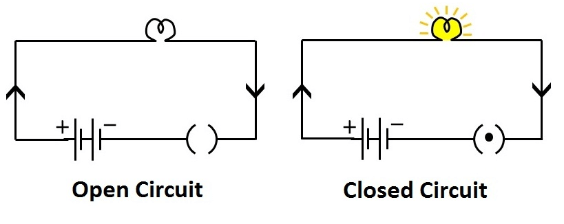
Figure 2: Open & Closed Circuits
Understanding open and closed circuits is needed to grasp how electrical systems work. These terms describe the state of the circuit and its ability to let electrical current flow.
Open Circuit
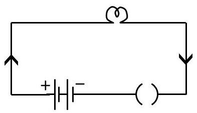
Figure 3: Open Circuits
When a circuit is broken at any point, it becomes an open circuit. In this state, the flow of electrical current stops completely, and any devices connected to the circuit, such as a lamp, will stop working. The open circuit prevents electrons from moving through the circuit, effectively stopping any electrical activity. In an open circuit, the full power (voltage) from the source, like a battery, is present at the break. What’s more, an open circuit might have a battery, wires, a lamp, and an open switch. When the switch is open, there is a gap in the circuit, and the lamp does not light up because no current flows.
Closed Circuit
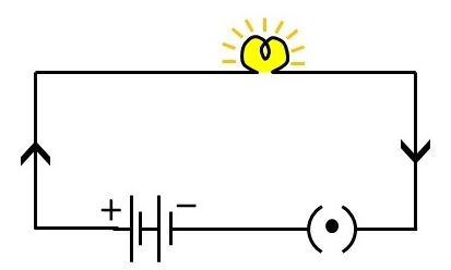
Figure 4: Closed Circuits
In a closed circuit, all parts are connected, and there is an unbroken path for current to move from one end of the power source to the other. Electrons travel from the negative end of the battery, through the wires, into the filament of the lamp, and then return to the positive end of the battery. This complete loop lets the lamp work. When the circuit is closed, current flows through the filament. The filament's resistance makes it heat up and emit light. The heat is produced because the electrons face resistance as they move through the filament, changing electrical energy into heat. A closed circuit includes a battery, wires, a lamp, and a closed switch. When the switch is closed, the circuit is complete, and the lamp glows because current flows through the whole loop.
Electron Flow in a Closed Circuit
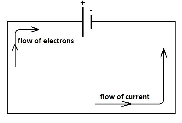
Figure 5: Electron Flow in a Closed Circuit
In a closed circuit, electrons move in a continuous loop, allowing electrical devices like lamps to work properly. This steady flow of electrons changes electrical energy into other forms of energy, like light and heat, which are needed for various devices to function. Let’s explore how this process works:
Start at the Negative Terminal
The process begins at the negative terminal of the battery, where electrons are pushed out due to a chemical reaction inside the battery. This reaction creates more electrons, making the terminal negatively charged. The battery acts like an electron pump, moving electrons because of the reactions happening inside it. These reactions cause a buildup of electrons at the negative terminal and a shortage at the positive terminal, creating a voltage between the two terminals.
Movement Through Conductive Wires
When electrons leave the negative terminal, they travel through the circuit's wires. These wires are usually made of copper or aluminum because these materials conduct electricity very well. The low resistance of these materials allows electrons to flow easily, losing very little energy as heat. This efficiency ensures that most of the electrical energy reaches the lamp. As the electrons move through the wires, they face very little resistance, allowing for a smooth and efficient transfer of energy.
Encountering Resistance in the Filament
When the electrons reach the lamp's filament, they face a lot of resistance. The filament is usually made of tungsten, a material chosen because it can handle high temperatures and doesn't melt easily. Unlike the wires that carry the electricity, the filament is designed to resist the flow of electrons. This resistance causes the electrons to bump into the atoms in the filament, turning electrical energy into heat. The heat makes the atoms move faster, causing the filament to get hot and emit light. This heating process is how traditional incandescent light bulbs work. The filament's high resistance ensures it gets hot enough to produce light and withstand the heat generated.
Continuation Through the Circuit
After passing through the filament, the electrons continue moving through the circuit. The filament's resistance has turned a lot of the electrical energy into light and heat, but the electrons still have enough energy to return to the battery. They move through the remaining wires, heading towards the positive end of the battery. The positive end, which has fewer electrons, pulls these electrons in, completing the loop. This ongoing flow of electrons, driven by the difference in charge created by the battery, is needed for the lamp to keep working. The battery keeps adding electrons at the negative end, ensuring a continuous flow of current through the circuit.
Maintaining a Closed Circuit
The continuous flow of electrons in a closed circuit is needed for the lamp to work well. Any break in the circuit, like a bad connection, a blown fuse, or an open switch, stops the flow of electrons and makes the lamp stop working. Keeping a closed circuit is needed for any electrical device to work correctly. Breaks in the circuit can cause problems, such as the device not working, possible damage to the parts, and safety risks. For example, a broken wire or a loose connection can create an open circuit, stopping the current and causing the lamp to go out. Similarly, a blown fuse can break the circuit to protect against too much current, stopping the flow of electrons and preventing damage or fire hazards.
Role of Resistance in Safety
Resistance plays a key role in keeping electrical circuits safe. It helps control the flow of current and makes sure devices work properly without getting damaged. For example, the resistance in a lamp's filament allows it to produce light and heat up without letting too much current pass through. This prevents the lamp from overheating and breaking.
In many electrical devices, resistance is used to manage how electrical energy is handled. By controlling resistance, we can make sure that the right amount of current flows through each part of a circuit, which is needed for safety and efficiency.
Enhancing Safety with Resistors
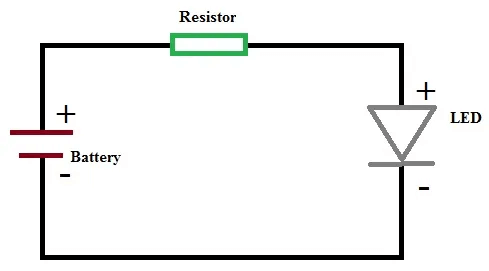
Figure 6: Diagram of a Resistor in a Circuit
Resistors are key parts in making electrical circuits safer. They limit the current to safe levels, protecting sensitive parts like LEDs, transistors, and integrated circuits from damage due to too much current. Without resistors, these parts could overheat and fail.
Circuit breakers and fuses are safety devices that use resistance to stop overheating and electrical fires. Circuit breakers automatically cut off the current when it exceeds a safe level. They use resistance to sense the current flow and break the circuit if the current is too high. Fuses contain a thin wire that melts when the current becomes too high, stopping the flow of electricity and preventing damage to the circuit.
Thermistors and varistors also help improve circuit safety. Thermistors are temperature-sensitive resistors that change their resistance with temperature changes. In circuits, they help protect against overcurrent conditions by increasing resistance when temperatures rise, thereby reducing the current flow. Varistors are voltage-dependent resistors that protect circuits from voltage spikes by changing their resistance in response to the applied voltage, thus preventing damage to sensitive components.
Troubleshooting and Repair
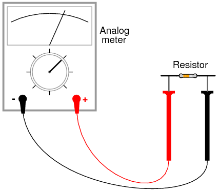
Figure 7: Troubleshooting and Repair
Understanding how resistance and current flow works is very useful for fixing electrical problems. Technicians and engineers use this knowledge to find issues like short circuits, where the current goes the wrong way, or open circuits, where the current path is broken. They look closely to find signs of damage such as burnt parts or melted insulation, which can show where a short circuit happened. By measuring resistance with a multimeter, they check for low resistance values that suggest a short circuit.
For open circuits, technicians use continuity testing with a multimeter to see if the current path is complete. A break in the path shows as infinite resistance or no continuity. Once the fault is found using tools like multimeters and oscilloscopes, they replace faulty resistors, capacitors, or other parts to fix the circuit. After fixing, they test the circuit to make sure it works correctly and safely.
Conclusion
Understanding how resistance works in electrical circuits is key to the operation and safety of many electronic devices. Resistance controls the flow of electric current, making sure that electrical components work safely. This article looks into the principles and uses of resistance in circuits, such as how resistors manage voltage and current, release heat, and stop dangers like short circuits. By examining how current flows through different materials and setups, we learn about the role of resistance in circuit design and operation. From simple electric lamps to complex signal conditioning and safety systems, resistance is a part of ensuring the efficiency and lifespan of electronic systems.
Frequently Asked Questions [FAQ]
1. What is resistance in a simple circuit?
Resistance in a simple circuit measures how much a material slows down the flow of electric current. When electric current flows, it moves electrons through the material. Resistance makes it harder for these electrons to move, similar to how friction slows down objects. The higher the resistance, the more difficult it is for the current to flow.
2. How does resistance affect electric current?
Resistance directly affects the flow of electric current in a circuit. Higher resistance reduces the flow of current, meaning fewer electrons can pass through the material. Conversely, lower resistance allows more current to flow. Think of it like a water pipe: a narrower pipe (higher resistance) lets less water through, while a wider pipe (lower resistance) lets more water flow.
3. How do you show resistance in a circuit?
In circuit diagrams, resistance is shown using a resistor symbol, which looks like a zigzag line. The value of the resistance, measured in ohms (Ω), is usually written next to this symbol. This helps identify how much the resistor will slow down the current in the circuit.
4. What is the basic principle of electrical resistance?
The basic principle of electrical resistance is that it opposes the flow of electric current. Different materials have varying levels of resistance. Materials with high resistance, like rubber, make it hard for current to flow, while materials with low resistance, like copper, allow current to flow easily. The resistance depends on factors like the material's properties, temperature, length, and cross-sectional area.
5. What happens if there is no resistance in a circuit?
If there is no resistance in a circuit, the electric current would flow without any restriction. This uncontrolled flow can lead to several problems. Overheating can occur because wires and components can overheat without resistance to limit the current, potentially causing burns or fire hazards. Damage to sensitive electronic components can happen due to excessive current, leading to malfunctions or failure. Safety hazards can arise since high currents can create dangerous conditions, including electric shocks and short circuits, posing serious risks to users and equipment.