on April 11th
604
The Role and Classification of Switching Equipment in Power Systems
Switchgear plays a very important role in the power system, ensuring the stability and safety of the power system. As power demand grows and the need for high-quality power increases, the complexity and variety of electrical switches have expanded. They've moved from basic manual operations to sophisticated automatic control systems to meet these demands. This exploration delves into the nuances of operating these switches, focusing on their design, function, and impact on power systems. However, switches come in various types, each with its specific design and purpose. There are currently four switch types: single-pole single-throw (SPST), single-pole double-throw (SPDT), double-pole single-throw (DPST), and double-pole double-throw (DPDT) switches. This article will introduce you to the type, function, and maintenance of the correct switch in detail. Please pay more attention to the importance of switches.
Catalog
Figure 1: Electrical Switches
Electrical switches are fundamental to managing and protecting power systems. They're far more than just basic tools for controlling current; they ensure power systems run safely and efficiently. Let's dive into their types and how they work.
Understanding Switches Types
Switches normally control the flow of electricity with a flip or press, similar to turning lights on or off. They are simple but top priority.
Circuit Breakers are advanced switches designed to handle normal currents and abruptly stop electricity during a short circuit, protecting the system from damage. They use special arc extinguishing chambers filled with materials like oil, air, sulfur hexafluoride (SF6), or vacuum to quickly cool and extinguish electrical arcs.
Isolating Switches provide a safe way to disconnect parts of a power system for maintenance, ensuring no current flows to that section. Load Switches allow circuits to be safely engaged or disengaged, even when carrying a load, offering flexibility for operational changes.
Fuses and power capacitors also provide necessary protection and efficiency improvements to power systems. Fuses melt to prevent overloads and short circuits, while capacitors enhance the performance of the electrical grid.
There are currently four main types of coaxial switches, namely SPST, SPDT, DPST, and DPDT. They demonstrate the adaptability of circuit design and allow complex control strategies to be employed within power systems, further illustrating the ability of circuit designers to implement complex flexibility in circuit functionality.
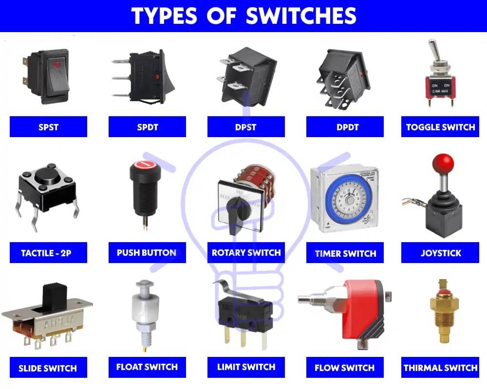
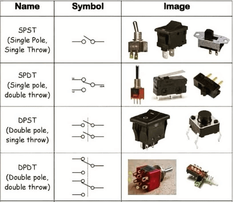
Figure 2: Types of Switches
Different Reactions to Switch Off
How do you know to turn off the switch correctly? Simply put, flipping a simple switch will make a clicking sound, which means the switch has completed your instructions and closed successfully.
However, the switch that engages the circuit breaker is usually via a mechanical interlock to ensure safety whether the switch is switched on or off. When a circuit breaker automatically trips, it responds quickly to protect the system and requires a manual reset to reconnect.
Using an isolating switch may require multiple steps to ensure safe disconnection of the circuit, including a verification process to ensure that no current is present.
Load switches and fuses provide behind-the-scenes security and often automatically reset or need to be replaced after being tripped, adding to the workload of maintaining switches.
The design complexity of switches, such as coaxial switches, requires a deep understanding of components such as ferrites and semiconductors, which impact performance metrics such as switching speed and reliability.
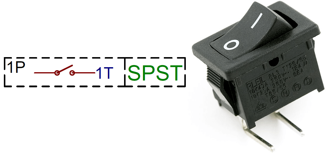
Figure 3: SPST Switches
A single-pole single-throw (SPST) switch is the simplest form of switch. Its straightforward design allows for the easy management of a circuit's power state, turning it on or off with a flick or press.
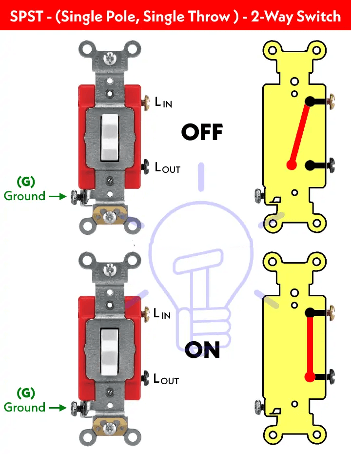
Basic Components: An SPST switch consists of a movable arm (the actuator) and two fixed contacts. When you press or flick the switch, the actuator moves to touch one contact (closing the circuit) allowing electricity to flow. Releasing the switch moves the actuator away, breaking the connection (opening the circuit) and stopping the current.
Design and Material Choices: The contacts are often made from a silver alloy, chosen for its excellent conductivity and resistance to corrosion. This ensures a reliable electrical connection even over small areas. The switch's body and actuator are crafted from durable materials like high-quality plastics or metals, offering the necessary strength, wear resistance, and insulation to guarantee both the switch's longevity and the user's safety.
Expanding Functions and Applications: While SPST switches primarily control power, creative wiring and integration with components like relays and sensors can enhance their functionality. This allows SPST switches to activate more complex sequences or safety mechanisms, expanding their utility beyond simple on-off actions.
Figure 4: SPST Structure
This switch has obvious features because of its simplicity. The hallmark of SPST switches is their simplicity and intuitive nature, making them ideal for straightforward circuit control tasks. Their reliability, ease of maintenance, and low cost come from this simplicity. However, their capability is limited to controlling a single circuit at a time, which may not suffice for more complex control needs requiring multiple circuits or intricate logic.
Technological advancements have led to the innovation of SPST switches, incorporating microelectronics for intelligent control and touch-sensitive operation. Future developments promise even more durable and efficient switches, thanks to new materials like nanomaterials and advanced alloys.
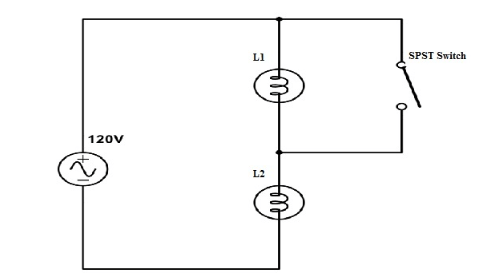
Figure 5: SPST Simple Circuit Diagram
SPST switches are foundational in both daily life and industry, representing a basic but essential building block in circuit design. Their ongoing evolution mirrors advances in technology, promising broader applications and enhanced functionality. Through understanding the principles and practicalities of SPST switches, we can appreciate their role in the past, present, and future of electrical engineering.
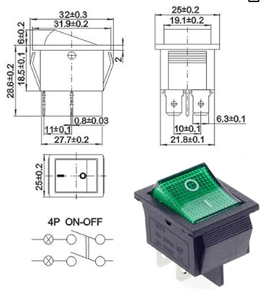
Figure 6: DPST Switches
A Double-Pole Single-Throw (DPST) switch is a crucial component in circuit design, enabling the control of two independent circuits with just one flick or press. This type of switch is specially designed to manage two separate pathways, each capable of making or breaking a connection independently, yet both are operated together, providing synchronous control over both circuits.
How It Works: The DPST switch's architecture is built around the idea of dual control but with unified action. When you activate the switch, it simultaneously establishes a connection in both circuits, allowing electricity to flow through each. Conversely, when you turn the switch off, it simultaneously cuts off the current in both circuits, ensuring a complete shutdown.
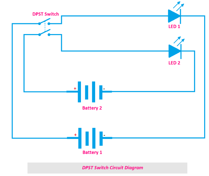
Figure 7: DPST Switches Circuit Diagram
Design Essentials: The design of a DPST switch focuses on simplifying tasks that require controlling two circuits at once. For instance, it can disconnect both the power and neutral lines to a device, ensuring it's entirely isolated from any electrical source.
Physical Structure: The switch comprises two channels or blades, each with input and output terminals for connecting the circuits. Activating the switch (turning it on) creates a bridge between these terminals, letting current flow freely. Turning the switch off breaks this bridge, halting current flow and ensuring the circuits are fully isolated.
DPST switches are integral to both household appliances and industrial machinery, particularly in cases requiring dual circuit control. Similarly, in industrial settings, they can simultaneously disconnect control circuits and main power supplies to avoid unintended operations.
Beyond basic on-off functions, DPST switches are adaptable for more complex control strategies. They can alter a device's operational state or mode by managing two power sources simultaneously, showcasing their importance in advanced circuit design.
The DPST switch's primary benefit is its ability to manage two circuits simultaneously, streamlining operations and reducing the need for multiple switches. This simplification extends to easier maintenance and operation.
Choosing a DPST switch requires attention to its electrical ratings to ensure it can handle the anticipated load safely. Additionally, considerations like the switch's physical dimensions and how it fits into a device are vital, especially in designs with limited space.
In essence, DPST switches are a blend of unique design and functional versatility. Their capability to control two circuits with a single action makes them invaluable for simplifying complex designs and enhancing safety across various applications.
A Single-Pole Double-Throw (SPDT) switch is a versatile tool in electrical engineering, designed to toggle between two different outputs with a single action. This flexibility makes SPDT switches more complex and useful than their Single-Pole Single-Throw (SPST) counterparts, as they can manage two circuits or devices, allowing for switching between them without needing extra switches.
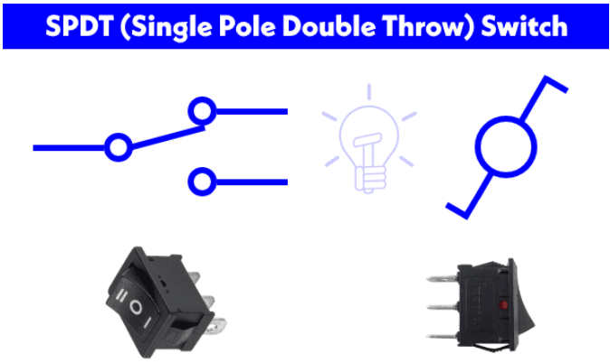
Figure 8: SPDT Switches
The working principle of the SPDT switch: The core mechanism of the SPDT switch is that it is connected to two output points: a normally open (NO) and a normally closed (NC). It has a common terminal (COM) and by default, COM is connected to NO or NC depending on the design of the switch. When you operate the switch, it shifts the connection from COM to either NO or NC, directing the current flow to the desired output. This capability offers precise control over circuit behavior, useful in scenarios ranging from safety systems to selecting operational modes. The NO and NC configuration adds versatility to circuit designs, ensuring a default state—either open or closed—when the switch is inactive. This characteristic is particularly valuable in applications requiring selective control or reverse operation.
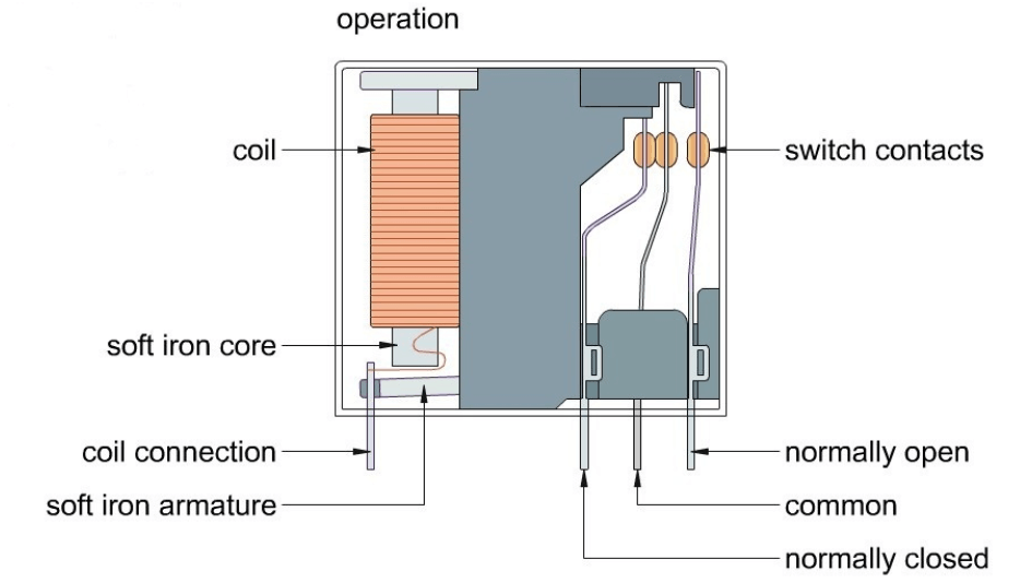
Figure 9: SPDT Relay Internal Structure
Practical Uses: SPDT switches find applications in various settings, from simple home lighting systems to sophisticated industrial controls. For instance, in a stair lighting system, SPDT switches at both the top and bottom of the staircase allow lights to be controlled from either end, enhancing convenience and safety.
Cost-Effectiveness and Reliability: Despite their control flexibility, SPDT switches remain affordable and reliable across various voltages and currents. They're adept at handling higher loads, making them suitable for controlling heavier machinery like relays, pumps, and motors.
Figure 10: SPDT Reply Circuit Schematic
Limitations: A notable limitation of SPDT switches is their inability to control two loads simultaneously. However, this can be addressed with thoughtful circuit design, employing multiple SPDT switches to achieve complex control strategies and logic.
Smart Integration: With technological advancements, SPDT switches are evolving, incorporating microcontrollers and connectivity features. This progression allows for both physical and software-based circuit management, heralding new possibilities in circuit design and control. SPDT switches play a pivotal role in electrical wiring and circuit design, thanks to their structure and operational flexibility.
Double-pole double-throw (DPDT) switches play a versatile and critical role in electrical engineering and electronics design, providing greater flexibility and control capabilities than single-pole double-throw (SPDT) switches. The DPDT switch can control the on and off of two independent circuits at the same time and allows each circuit to have two different states.
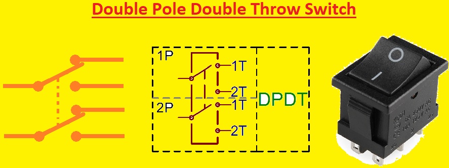
Figure 11: DPDT Switches
Working Principle and Structural Characteristics
A Double-Pole Double-Throw (DPDT) switch is a multifunctional component in electrical and electronic projects, offering a level of control and versatility surpassing that of Single-Pole Double-Throw (SPDT) switches. Essentially, a DPDT switch can manage two separate circuits, directing each to one of two states simultaneously with a single manual action.
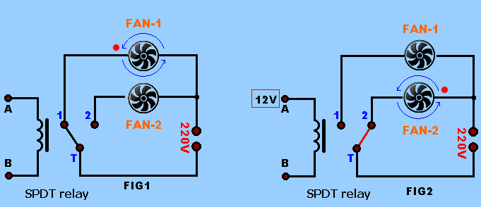
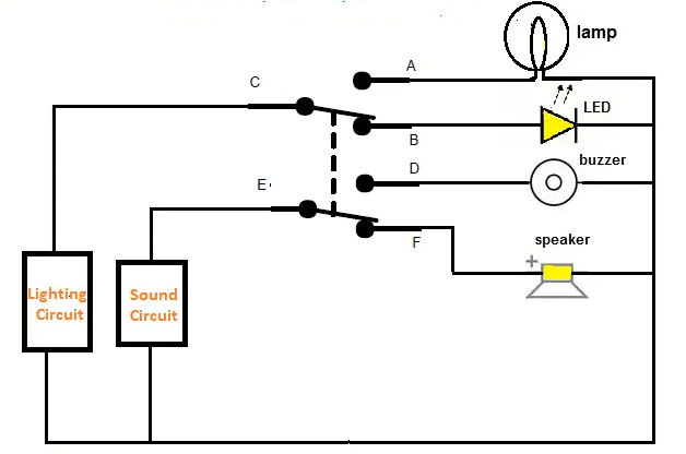
How They Work: At the heart of a DPDT switch are two sets of terminals connected to two control arms (the "double pole"), and each set can engage with one of two outputs (the "double throw"). This configuration allows the switch to direct two circuits to alternate between two different outcomes. Flipping a single switch that not only turns a light on or off but also simultaneously decides if a fan should spin clockwise or counterclockwise.
Figure 12: DPDT Simple Circuit Diagram
Switch Configurations: DPDT switches often come in "ON-ON" or "ON-OFF-ON" setups, giving you the power to determine the operational state of connected circuits—be it changing the polarity of a current, rerouting signals, or selecting power sources. This adaptability opens up a myriad of design possibilities.
Material and Construction: For a DPDT switch to last and perform reliably, its contacts are typically made from materials like silver alloy or goldplating, known for their excellent electrical conductivity and resistance to corrosion. The switch's mechanical parts are designed for endurance and smooth operation, ensuring it can withstand regular use without faltering.
Applications: From everyday gadgets to sophisticated industrial systems, DPDT switches are everywhere. They serve as critical components in automated systems for selecting control signals or changing motor rotation direction. Audio equipment uses them to choose signal paths, while hobbyists might find them in model kits or remote controls, manipulating various functions.
While DPDT switches enhance design flexibility, they also present challenges, like maintaining consistent reliability across all states and fitting complex switching capabilities into compact designs. Addressing these issues might involve innovations in miniaturization, the use of advanced materials, and the incorporation of smart control features. DPDT switches stand out for their unique ability to control multiple circuits in varied configurations. Understanding their operation, design considerations, and applications sheds light on their essential role in electronic and electrical engineering.
Figure 13: Switches Selection
Choosing the right switches and relays for your needs involves more than just picking parts off the shelf. Because it involves understanding each component's design, functionality, and how it meets your system needs.
Packaging Commonality: Manufacturers often standardize the external packaging of switches and relays across different models. This standardization helps streamline production and inventory processes. For instance, a DPST switch and a DPDT switch might look identical from the outside because they share the same housing design. However, their internal mechanisms and functionalities can differ greatly. This is why appearances can be deceiving. Always consult the datasheet in detail to ensure the component you select meets both the electrical and functional needs of your project.
Operation Type: No matter which switch operating mechanism you choose (whether momentary or maintained), it must match your needs. Momentary switches, which activate only while being pressed and revert upon release, are ideal for applications requiring short signals, like doorbell systems or computer keyboards. On the other hand, hold-type switches maintain their state until they're actuated again.
Paying Attention to Details: The specifications sheet for even the simplest switch or relay is packed with critical information. Parameters like electrical life, contact resistance, operating temperature, and material can dictate whether a component will perform as expected in your application. For example, if your project involves high temperatures, you'll need switches and relays that can tolerate those conditions. Similarly, for high-frequency signal applications, choosing components with minimal contact resistance variation is crucial.
Cost and Performance: While it's tempting to go with the cheapest option, saving money upfront can sometimes lead to higher costs due to breakdowns, maintenance, and replacements. Therefore, we need to consider whether the factors of cost and expected performance and life of components can coexist at the same time.
The evolution of electrical switchgear and protection mechanisms marks a significant journey from basic mechanical switches to today's sophisticated automatic control systems. These developments reflect not just technological advancement but also a growing need for safety and reliability in managing power systems.
From Mechanical to Automatic
The design journey of switchgear has seen the transition from straightforward mechanical switches, used for simple on-off operations, to complex, automated systems that ensure circuit safety and efficiency. These modern systems don't just switch circuits on or off, they monitor and protect against potential dangers like overloads or short circuits.
The Role of Circuit Breakers
At the heart of switchgear systems lies the circuit breaker, designed to manage both normal and excessive loads. Under ordinary conditions, it connects or disconnects circuits. In emergencies like overcurrent, it automatically shuts off power, protecting the circuit from damage. Today’s breakers utilize various arc extinguishing methods—air, oil, vacuum, or SF6—each chosen for its specific benefits in different applications.
Protection Relays and System Monitoring
Working alongside current and voltage transformers, protection relays continuously scan for irregularities in the power system's vital signs, including current, voltage, frequency, and phase angle. Upon detecting any anomaly, they command circuit breakers to isolate the fault, safeguarding the rest of the grid from potential harm.
The Switch Cabinet's Instruments
Beyond switching, the switch cabinet houses tools for measuring and controlling the power grid's performance. These instruments are indispensable for maintaining the efficiency and quality of the power supply, allowing for real-time adjustments and monitoring.
Designing for Safety
High and ultra-high-voltage systems pose unique challenges, requiring intricate, reliable protection strategies. Engineers must anticipate a range of fault scenarios, crafting protection schemes that respond swiftly and accurately to maintain system stability.
Choosing the Right Components
Selecting switchgear and protection components involves weighing electrical performance against physical size, environmental suitability, and cost. The right choices ensure not only the system's reliability but also its economic efficiency.
Electrical switchgear and protection systems play a pivotal role in keeping power networks safe and efficient. Diving deep into the various switch types sheds light on their distinct roles and how they collectively contribute to the power system's stability. Electrical switchgear and protection systems are fundamental to the operation of modern power networks. Their development reflects a blend of responding to current needs and anticipating future challenges. For professionals in the field, staying informed about technological advancements and integrating them into system designs is key to achieving optimal power system performance and safety. As we push forward technologically, the complexity and effectiveness of these systems are on the rise, meeting today's energy demands while paving the way for more secure and efficiently managed future power grids.
Frequently Asked Questions [FAQ]
1. What are the three types of electrical switches?
Mechanical switches, solid-state switches, magnetic switches.
2. What are the 2 most common types of switches?
Mechanical Switches: Mechanical switches are very common in both domestic and industrial settings due to their simplicity of operation, low cost, and ease of maintenance.
Solid-state switches: Despite their relatively high cost, solid-state switches are widely used in many modern electronic and automation devices due to their durability, fast response, and low power consumption.
3. What are the 4 types of electrical switches in the home?
Single pole single throw switch (SPST), double pole single throw switch (DPST), single pole double throw switch (SPDT), double pole double throw switch (DPDT).
4. What are the different types of mechanical switches?
Push button switch: Control the opening and closing of the circuit by pressing the button.
Toggle switch: Change the circuit status by toggle the lever.
Rotary switch: Select different circuit connections by rotating the lever.
Slide switch: A sliding component that switches a circuit on or off or selects an operating mode.
5. What type of switch is the most commonly used in residential wiring?
In residential wiring, single pole single throw switches (SPST) are the most commonly used type.
switchgear, power system, electrical switches, automatic control systems, manual operations, single-pole single-throw (SPST), single-pole double-throw (SPDT), double-pole single-throw (DPST), double-pole double-throw (DPDT), circuit breakers, isolating switches, load switches, fuses, power capacitors, coaxial switches, mechanical switches, solid-state switches, magnetic switches.
Share: