Navigating the World of Three-Phase Motors: Types, Functions, and Operational Insight
The industrial sector heavily relies on electric motors, particularly three-phase induction motors, which are celebrated for their efficiency, reliability, and durability. These motors, especially squirrel-cage and wound-rotor types, along with synchronous motors, are dynamic in driving machinery and supporting required operations across various industries. This article digs into the mechanics and specific applications of these motors, highlighting how their distinct characteristics cater to particular industrial needs, thereby aiding in the design of effective and efficient systems.
It further explores the basic operating principles of these motors, elucidates the differences between them, and discusses technological advancements that have expanded their functionality and application range. In addition, the artifact examines the significant impact of these motors in diverse sectors such as manufacturing, energy production, and HVAC systems. By providing a comprehensive overview of their roles, the article offers valuable insights into the integral part these motors play in modern industrial setups.
Catalog
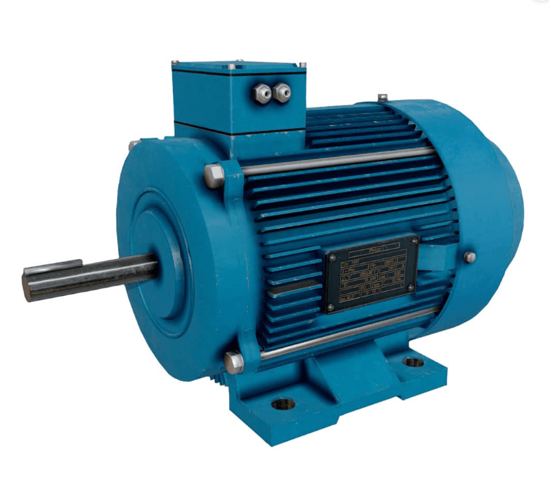
Figure 1: Squirrel-Cage Induction Motors
Understanding Squirrel-Cage Induction Motors
The three-phase squirrel-cage induction motor is a needed component in industrial machinery, celebrated for its robust design and dependable performance. It comprises two main parts: the stator and the rotor. The rotor, which is devoid of windings, consists of conductive metal bars running parallel to the shaft, connected at both ends by circular metal rings, creating a structure reminiscent of a cage. This specific design not only facilitates the induction of electromagnetic forces but also minimizes maintenance needs and boosts durability.
During operation, three-phase AC power supplied to the stator windings generates a rotating magnetic field. This field interacts with the rotor, inducing an electromotive force (EMF) in the metal bars. The interaction between the induced current and the magnetic field produces torque, propelling the machinery. The rotor's speed, however, typically trails the stator's magnetic field speed—known as synchronous speed—due to mechanical and electrical losses like friction and windage, a disparity referred to as rotor slip. Usually, adjusting the motor's speed involved changing the power frequency or the physical configuration of the poles, both methods being impractical for regular applications.
The advent of electronic variable-speed drives has significantly enhanced the functionality of squirrel-cage motors. These devices control motor speed by altering the frequency of the power supply, converting AC power to DC, and then using semiconductor devices to generate variable frequency AC power. Furthermore, changing the rotation direction of the motor is as simple as swapping two of the three-phase power connections, such as T1 and T3, which reverses the stator's magnetic field direction and thus the rotor's rotation. This level of control and adaptability solidifies the squirrel-cage induction motor's key role in modern industrial setups, embodying simplicity, reliability, and flexibility—key attributes for dynamic industrial environments.
Diverse Uses of Squirrel-Cage Induction Motors
Squirrel-cage induction motors are dynamic in many industrial operations due to their reliability and robust performance. These motors are commonly used in various sectors to drive needed equipment like pumps, compressors, and conveyor systems. Their design ensures consistent torque and speed, which is significant for machinery requiring steady and reliable operation over long periods. These motors excel in tough conditions with minimal maintenance, making them requisite in industrial applications.
In Heating, Ventilation, and Air Conditioning (HVAC) systems, squirrel-cage motors are key components in large-scale commercial and industrial installations. They drive fans and blowers that circulate air and regulate climate conditions, maintaining air quality and comfortable temperatures. The reliability of these motors ensures efficient operation of HVAC systems, reducing downtime and lowering energy consumption. This is especially imperative for large facilities like factories, office buildings, and hospitals.
Squirrel cage motors also play a significant role in power generation. They can be configured to work as generators through a process called induction generation. When a prime mover, such as a turbine or windmill, mechanically drives the rotor of a squirrel-cage motor, the motor acts in reverse to produce electricity. This happens by inducing an electromotive force across the stator windings as the rotor turns, converting mechanical energy back into electrical energy. This capability is particularly valuable in remote locations or as part of emergency power systems in serious facilities where reliable grid access is unavailable. In the event of grid power failure, these motor-turned-generators provide needed backup power, ensuring continuous operations and safety.
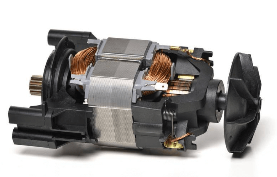
Figure 2: Wound-Rotor Induction Motors
Introduction to Wound-Rotor Induction Motors
Wound-rotor induction motors are designed for applications requiring precise variable speed control. Even with the rise of electronic variable-frequency drives, these motors remain useful in situations where detailed control is significant. Unlike squirrel-cage motors, wound-rotor motors feature rotors with windings connected to an external circuit via slip rings and brushes.
When three-phase power is applied to the stator, it creates a rotating magnetic field. This field induces electromotive forces in the rotor windings, generating a magnetic field that propels the rotor. The strength of the rotor's magnetic field, and thus the motor's speed, can be finely tuned by adjusting external resistances connected through the slip rings and brushes. A three-phase rheostat is typically used for these adjustments, allowing precise speed control under varying load conditions. Modern systems often automate these adjustments, improving efficiency and responsiveness.
Reversing the rotation direction in wound-rotor motors is simple. It involves switching any two stator leads, similar to the process in squirrel-cage motors. Despite their control benefits, wound-rotor motors are generally more expensive and require more maintenance due to the wear on brushes and slip rings. In addition, the advantages of variable speed control are less pronounced with the advent of advanced variable-frequency drives, leading to a decline in their use in new installations. However, in applications where precise speed modulation is dynamic and the physical connection via slip rings offers a benefit, wound-rotor motors remain a valuable option.
Practical Applications of Wound-Rotor Induction Motors
Wound-rotor induction motors are useful in applications that require precise control of motor speed and torque. Their unique design and functionality make them ideal for heavy-duty uses in various industries.
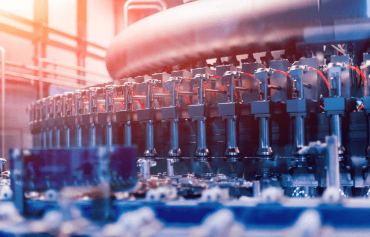
Figure 3: Manufacturing and Construction
In manufacturing and construction, these motors are dominant for operating cranes and hoists. Their ability to finely adjust speed allows for smooth and controlled lifting and movement of heavy materials, which enhances safety and operational efficiency.

Figure 4: Mining
In mining, wound-rotor motors power help machinery such as conveyor belts and drilling equipment. Their robust design and precise control capabilities help manage substantial mechanical loads and variable speed needs. This optimizes extraction processes, reduces mechanical stress, and extends the life of equipment.
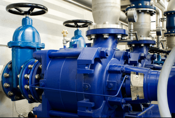
Figure 5: Industrial Pumps
These motors are also risky for driving large-scale industrial pumps. Variable speed control is compulsory to adjust flow rates and optimize energy use. By enabling precise motor operation, wound-rotor motors help maintain ideal operating conditions, improving overall energy efficiency. This is particularly valuable in industries where energy costs are a significant part of operational expenses.
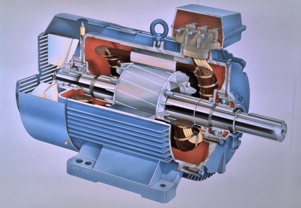
Figure 6: Synchronous Motors
Details of Synchronous Motors
Synchronous motors are a specialized type of three-phase motor known for maintaining a constant speed, regardless of load changes. This stability is due to their unique construction, which includes a three-phase stator and a wound rotor with slip rings and brushes. The rotor features a single winding with shorting bars.
Startup Phase: During startup, three-phase AC power is applied to the stator, generating a rotating magnetic field. This field induces a voltage in the rotor's shorting bars, creating current and its magnetic field. As the motor approaches its operational speed, DC power is supplied to the rotor windings. This transition turns the rotor into a strong electromagnet that locks into synchronization with the stator’s rotating magnetic field, ensuring consistent speed operation.
Caution During Startup: It is risky not to apply DC power to the rotor windings during startup. Doing so can cause significant motor damage due to excessive torque and mechanical stress.
Reversing Direction: To reverse the motor's direction, simply interchange two of the stator leads, typically T1 and T3. This swap reverses the direction of the stator's magnetic field, changing the rotor's rotation direction. This feature is particularly useful for applications requiring bidirectional operation without complex control systems.
Exploring Synchronous Motor Applications
Synchronous motors are dynamic in applications requiring exact speed regulation and synchronization with the power grid. These motors excel in situations where precision and efficiency are serious.
Power Generation: In power plants, synchronous motors serve dual roles. They drive pumps and compressors as motors and convert mechanical power into stable electrical power as generators. This dual functionality is dynamic for maintaining the balance and stability of the power grid.
Marine Sector: In the marine sector, synchronous motors are key to ship propulsion systems. Their ability to maintain constant speed, despite load variations, ensures efficient and controlled navigation. This is particularly beneficial for large vessels that need consistent thrust for maneuvering and long-distance travel.
Industrial Applications: Synchronous motors are widely used in industrial applications requiring precise speed control. They drive high-performance machinery such as industrial compressors and centrifugal pumps, which are the key for processes needing meticulous flow control and pressure settings. Precise speed regulation minimizes energy consumption and enhances process efficiency.
Anatomy of a 3-Phase Induction Motor Stator
The stator is a dominant stationary part of a three-phase induction motor. It comprises three main components: the stator casing, the core, and the winding. Each part plays a dynamic role in the motor's function and efficiency.
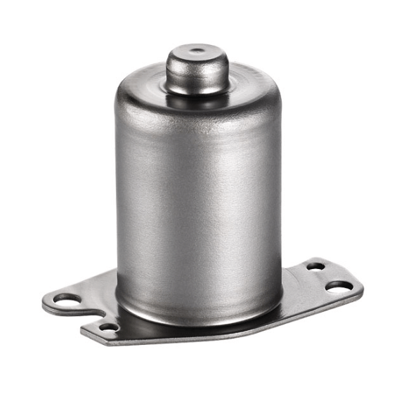
Figure 7: Stator Casing
The stator casing, or frame, is the motor's sturdy outer shell. It provides mechanical support and maintains the structural integrity of the core and windings. The casing also aids in heat management. External fins on the casing increase the surface area, improving heat dissipation. Materials used for the casing, such as die-cast or fabricated steel, aluminum alloys, or corrosion-resistant stainless steel, are selected based on the motor's operational demands and environmental conditions.

Figure 8: Stator Core
The core channels the alternating magnetic flux needed for motor operation. To minimize hysteresis and eddy current losses, the core is made from laminated silicon steel sheets, each 0.3 to 0.6 mm thick. These laminations are insulated from one another to prevent electrical losses and are precisely stacked to form the core. The core's inner surface has multiple slots to accommodate the stator windings, optimizing magnetic flux distribution.
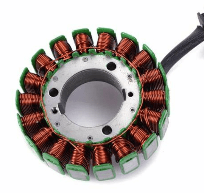
Figure 9: Stator Winding
The stator winding, placed within the core slots, consists of copper or aluminum conductors arranged in three phases connected to an external three-phase power supply. This setup determines the motor's speed and torque output. The number of poles in the winding affects the motor's speed: more poles reduce the speed, and fewer poles increase it. The windings are typically configured in a star or delta formation, based on the motor’s starting requirements and application. All connections lead to a terminal box attached to the stator casing, housing six terminals (two for each phase), allowing flexible electrical connections suited to the motor’s application.
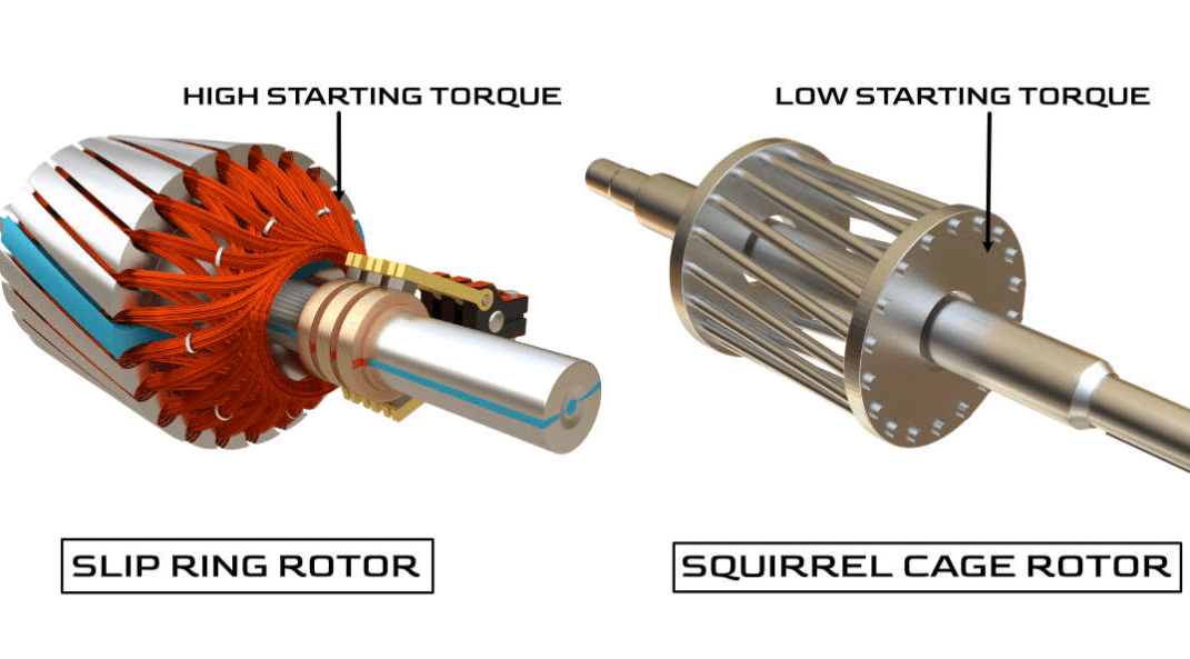
Figure 10: Comparing Slip Ring & 3 Phase Squirrel Cage Induction Motor
Comparing Slip Ring and Squirrel-Cage 3-Phase Induction Motors
Squirrel-cage induction motors and slip-ring motors are both needed in the industry, but they serve different functions based on their construction, operation, and maintenance needs.
|
Feature Comparison |
Squirrel Cage Motors |
Slip Ring Motors |
|
Rotor Construction |
These motors have a simple rotor made of shorted conductors forming a cage-like structure. This design is durable and less prone to malfunctions.
|
These motors have a more complex wound rotor connected to an external circuit through slip rings and brushes, offering greater control over performance. |
|
Speed Control |
The speed is typically fixed based on the AC power supply frequency and the motor’s physical properties. Speed variations require additional devices like variable-frequency drives.
|
These motors allow intrinsic speed adjustment by modulating external resistances connected across the slip rings, providing finer operational control.
|
|
Applications |
Due to their simplicity and reliability, they are used in general-purpose applications across various industries.
|
Preferred in applications needing precise speed control and high starting torque, such as heavy load lifting or where variable speed is significant.
|
|
Maintenance |
Virtually maintenance-free, as they lack brushes and slip rings, reducing wear components.
|
Require regular maintenance for brushes and slip rings, which affects long-term operational costs and downtime |
|
Efficiency |
Generally, more efficient due to their simpler design, minimizing energy losses.
|
Typically face higher operational losses due to friction and resistance in the brushes and slip rings. |
|
Cost |
Cost-effective and widely preferred for a broad range of industrial applications.
|
More expensive due to their complexity and higher maintenance costs, making them less common. |
|
Starting Torque |
- |
Provide high starting torque without drawing excessive current by adjusting external resistances during startup. This is advantageous in applications starting under heavy load or requiring a gentle start to minimize mechanical stress.
|
|
Common Usage |
Ubiquitous across industries for their robustness and ease of use. |
Requisite in scenarios requiring precise control over motor speeds and torque, despite being less common. |
|
Complexity |
Simpler construction with fewer moving parts makes them less susceptible to mechanical failures. |
More components, including slip rings and brushes, increase their complexity and maintenance needs. |
Benefits of Using 3-Phase Induction Motors
Three-phase induction motors are widely valued in various industries due to their significant benefits, which stem from their design and operational efficiency.
|
Benefits of 3-Phase Induction Motor |
|
|
Simple and Rugged Construction |
Three-phase induction motors feature a straightforward yet robust design with fewer moving parts. This simplicity enhances their durability and reliability, making them ideal for demanding industrial environments where they face continuous operation and potential mechanical stresses.
|
|
Low Maintenance |
The uncomplicated construction of these motors results in minimal maintenance requirements. They do not have brushes or commutators, common in other motor types, which often need frequent inspection and replacement. This characteristic significantly reduces the lifetime cost by minimizing downtime and maintenance expenses. |
|
High Efficiency and Power Factor |
Three-phase induction motors are designed for high efficiency and a favorable power factor. High efficiency is key for reducing energy consumption and operational costs, especially in applications requiring continuous motor operation. These motors generally have a power factor close to unity under full load conditions, reducing the reactive power component in power systems and enhancing overall electrical system efficiency.
|
|
Cost-Effective |
Compared to other motor types, three-phase induction motors are more economical both in the initial purchase price and over their lifespan. Their sturdy construction, low maintenance needs, and high efficiency contribute to a lower total cost of ownership.
|
|
Self-Starting Capability |
Three-phase induction motors can start on their own without external starting mechanisms. This self-starting feature is particularly valuable in automated industrial processes where minimal manual intervention is desired. It simplifies system design and reduces additional costs related to external starters.
|
Limitations of 3-Phase Induction Motors
While three-phase induction motors are favored for their reliability and efficiency, they have certain limitations that may affect their suitability for specific applications.
|
Limitations of 3-Phase Induction Motor |
|
|
Challenging Speed Control |
Three-phase induction motors are typically designed to operate at a constant speed, determined by the AC power supply frequency and the motor's physical characteristics (like the number of poles). Adjusting the speed dynamically is complex and often requires additional systems, such as variable frequency drives (VFDs). This makes them less flexible compared to DC or variable-speed motors, where speed control is more straightforward and intrinsic.
|
|
Low Starting Torque and High Inrush Currents |
These motors have relatively low starting torque compared to other motor types, like synchronous motors. This can be a drawback in applications requiring heavy initial load movement. In addition, they draw inrush currents significantly higher than their normal operating current—often 4 to 8 times the rated current—when first started. This high initial surge can cause voltage drops and impact electrical systems, potentially requiring soft starters or other current-limiting technologies to mitigate these effects |
|
Lagging Power Factor at Light Loads |
Three-phase induction motors generally operate with a lagging power factor, which worsens under light load conditions. At light loads, the power factor can drop to as low as 0.3 to 0.5 lagging. This poor power factor leads to inefficient power usage and increased demand charges in industrial electricity bills. Correcting the power factor often requires additional equipment, such as capacitors, adding to the overall system cost and complexity.
|
Conclusion
Three-phase induction motors, particularly the squirrel-cage and wound-rotor types, as well as synchronous motors, play dynamic roles across a range of industrial applications due to their distinctive properties and operational efficiencies. The squirrel-cage motor is celebrated for its durable design and minimal maintenance needs, making it ideal for general-purpose applications in harsh industrial environments.
In difference, the wound-rotor motor, with its adjustable speed and high starting torque, is required for applications requiring precise control over motor dynamics. Synchronous motors are requisite in scenarios demanding exact speed regulation and power generation. Despite their inherent limitations such as complex speed control and low starting torque, the introduction of variable-frequency drives and other modern technologies has significantly mitigated these issues, enhancing the motors' functionality and application. The ongoing development and integration of these motors underscore their required role in enhancing industrial efficiency and productivity, proving significant for future technological advancements and energy management strategies.
Frequently Asked Questions [FAQ]
1. What is the meaning of a three-phase motor?
A three-phase motor is an electric motor designed to operate on three phases of alternating current (AC). Unlike single-phase motors, three-phase motors benefit from a continuous flow of power due to the phases being staggered, resulting in smoother and more efficient operation. This type of motor is commonly used in industrial applications where high power and efficiency are needed.
2. What do three-phase motors operate on?
Three-phase motors operate on three-phase electrical power, which is a common method of electrical power transmission in industrial environments. This power type consists of three alternating currents that are out of phase with each other by 120 degrees, ensuring a constant power delivery to the motor, which improves efficiency and torque.
3. Which law is used in the principle of operation of a 3-phase induction motor?
The operation of a three-phase induction motor is based on Faraday's law of electromagnetic induction. When the three-phase voltage is applied to the stator windings of the motor, it creates a rotating magnetic field. This field interacts with the conductors in the rotor, inducing a current and magnetic field in the rotor due to the relative motion between the rotating stator field and the stationary rotor conductors, which makes the rotor turn.
4. What is the construction and working of a three-phase induction motor?
Construction: A three-phase induction motor consists of two main parts: the stator and the rotor. The stator is the stationary part that houses coils of wire, which are connected to the three-phase AC supply. The rotor is located inside the stator and is free to rotate.
Working: When a three-phase current flows through the stator, it generates a rotating magnetic field that interacts with the rotor. The changing magnetic field induces an electromotive force (EMF) in the rotor due to electromagnetic induction, producing a current. The interaction between the magnetic fields of the stator and rotor causes the rotor to turn, thus converting electrical energy into mechanical energy.
5. How do I know if my motor is 3-phase?
You can identify a three-phase motor by looking at several key features:
Wiring: Check the motor’s terminal box; a three-phase motor typically has three or more wires (excluding the ground wire), each representing a phase.
Nameplate: The motor’s nameplate usually specifies if it is three-phase, along with other details like voltage, current, and power ratings.
Physical Configuration: Three-phase motors are often larger and have a more robust construction compared to single-phase motors due to their industrial application.
Voltage Ratings: Three-phase motors often operate at higher voltage ratings, common in industrial settings.
About us
ALLELCO LIMITED
Read more
Quick inquiry
Please send an inquiry, we will respond immediately.
How to Read an Ohmmeter Resistance Measurement?
on June 22th
SPI Demystified Exploring the Fundamentals of Serial Peripheral Interface
on June 21th
Popular Posts
-

What is GND in the circuit?
on January 1th 2937
-

RJ-45 Connector Guide: RJ-45 Connector Color Codes, Wiring Schemes, R-J45 Applications, RJ-45 Datasheets
on January 1th 2498
-

Fiber Connector Types: SC Vs LC And LC Vs MTP
on January 1th 2089
-

Understanding Power Supply Voltages in Electronics VCC, VDD, VEE, VSS, and GND
on November 9th 1888
-

Comparison Between DB9 and RS232
on January 1th 1761
-

What Is An LR44 Battery?
Electricity, that ubiquitous force, quietly permeates every aspect of our daily lives, from trivial gadgets to life-threatening medical equipment, it plays a silent role. However, truly grasping this energy, especially how to store and efficiently output it, is no easy task. It is against this background that this article will focus on a type of coin cell battery that may seem insignificant on the...on January 1th 1712
-

Understanding the Fundamentals:Inductance Resistance, andCapacitance
In the intricate dance of electrical engineering, a trio of fundamental elements takes center stage: inductance, resistance, and capacitance. Each bears unique traits that dictate the dynamic rhythms of electronic circuits. Here, we embark on a journey to decipher the complexities of these components, to uncover their distinct roles and practical uses within the vast electrical orchestra. Inductan...on January 1th 1651
-

CR2430 Battery Comprehensive Guide: Specifications, Applications and Comparison to CR2032 Batteries
What is CR2430 battery ?Benefits of CR2430 BatteriesNormCR2430 Battery ApplicationsCR2430 EquivalentCR2430 VS CR2032Battery CR2430 SizeWhat to look for when buying the CR2430 and equivalentsData Sheet PDFFrequently Asked Questions Batteries are the heart of small electronic devices. Among the many types available, coin cells play a crucial role, commonly found in calculators, remote controls, and ...on January 1th 1548
-

What Is RF and Why Do We Use It?
Radio Frequency (RF) technology is a key part of modern wireless communication, enabling data transmission over long distances without physical connections. This article delves into the basics of RF, explaining how electromagnetic radiation (EMR) makes RF communication possible. We will explore the principles of EMR, the creation and control of RF signals, and their wide-ranging uses. The article ...on January 1th 1537
-

CR2450 vs CR2032: Can The Battery Be Used Instead?
Lithium manganese batteries do have some similarities with other lithium batteries. High energy density and long service life are the characteristics they have in common. This kind of battery has won the trust and favor of many consumers because of its unique safety. Expensive tech gadgets? Small appliances in our homes? Look around and you'll see them everywhere. Among these many lithium-manganes...on January 1th 1506
HOT Part Number
-
DW025CL-M
ABB Power Electronics Inc.
DC DC CONVERTER +/-15V 25W
AOD603A
Alpha & Omega Semiconductor Inc.
MOSFET N/P-CH 60V TO252-4L
BCX54-10,115
Nexperia USA Inc.
TRANS NPN 45V 1A SOT89
TL064ACDR
Texas Instruments
IC OPAMP JFET 4 CIRCUIT 14SOIC
MX25U1635EM1I-10G
Macronix
IC FLASH 16MBIT SPI/QUAD 8SOP
F1827DH1000
Sensata-Crydom
MODULE SCR/DIODE 25A 380VAC
VI-J11-EX
Vicor Corporation
DC DC CONVERTER 12V 75W
HD64F3684FPV
Renesas Electronics America Inc
IC MCU 16BIT 32KB FLASH 64LQFP
ST1S15J18R
STMicroelectronics
IC REG BCK 1.82V 500MA 6FLIPCHIP
MB90347ESPMC-GS-697E1
Infineon Technologies
IC MCU 16BIT 128KB MROM 100LQFP
AFE7222IRGCR
Texas Instruments
IC AFE 4 CHAN 12BIT 64VQFN
RLB1314-103KL
Bourns Inc.
FIXED IND 10MH 100MA 12 OHM TH
046232122103800+
KYOCERA AVX
CONN FFC FPC TOP 22POS 1MM R/A
SIS444DN-T1-GE3
Vishay Siliconix
MOSFET N-CH 30V 35A PPAK1212-8
87972DYI-147LFT
Renesas Electronics America Inc
IC CLOCK MULTIPLIER 52TQFP
DS90UB913ATRTVTQ1
Texas Instruments
IC SER/DES 10-100MHZ FPD 32WQFN
1812HA390MAT1A
KYOCERA AVX
CAP CER 39PF 3KV NP0 1812
MBR6080
GeneSiC Semiconductor
DIODE SCHOTTKY 80V 60A DO5 -

06033D153MAT2A
KYOCERA AVX
CAP CER 0.015UF 25V X5R 0603
DAC108S085CIMT
Texas Instruments
IC DAC 10BIT V-OUT 16TSSOP
PM75CLA060
Powerex Inc.
MOD IPM L-SERIES 600V 75A
DRV5053RAQDBZRQ1
Texas Instruments
SENSOR HALL ANALOG SOT23-3
CC0402KRX7R7BB681
YAGEO
CAP CER 680PF 16V X7R 0402
TMM-108-01-L-S-SM-P
Samtec Inc.
2MM TERMINAL STRIP
BT138-600D,127
NXP USA Inc.
NOW WEEN - BT138-600D - 4 QUADRA
CY7C1049CV33-12ZSXAT
Infineon Technologies
IC SRAM 4MBIT PARALLEL 44TSOP II
EP3C40F484C6N
Intel
IC FPGA 331 I/O 484FBGA
XC7A100T-2FGG676C
AMD
IC FPGA 300 I/O 676FBGA
SMCJ40A
Taiwan Semiconductor Corporation
TVS DIODE 40VWM 64.5VC SMC
LM53625LQRNLRQ1
Texas Instruments
IC REG BUCK 5V 2.5A 22VQFN
RG2012L-223-L-T05
Susumu
RES SMD 22K OHM 0.01% 1/10W 0805
CIL10J2R2KNC
Samsung Electro-Mechanics
FIXED IND 2.2UH 15MA 1.15OHM SMD
SN74LVC1G06DRLR
Texas Instruments
IC BUFFER INVERT 5.5V SOT5
BQ7790509PWR
Texas Instruments
IC BATT PROT LI-ION 3-5C 20TSSOP
VI-2N4-CU
Vicor Corporation
DC DC CONVERTER 48V 200W
12102C103MAT4A
KYOCERA AVX
CAP CER 10000PF 200V X7R 1210 -

4532-201-LF
YAGEO
GDT 200V 2KA 2 POLE SMD
LTM4650MPY#PBF
Analog Devices Inc.
DC DC CNVRTR 0.6-1.8V 0.6-1.8V
TJA1057GTKZ
NXP USA Inc.
IC TRANSCEIVER HALF 1/1 8HVSON
PAH150S48-3.3
TDK-Lambda Americas Inc
DC DC CONVERTER 3.3V 150W
PCA9701PW
Freescale Semiconductor
IC XPNDR 5MHZ SPI SERIAL 24TSSOP
S34ML04G200TFI003
Cypress Semiconductor Corp
IC FLASH 4GBIT PARALLEL 48TSOP
08051C183KAT9A
KYOCERA AVX
CAP CER 0.018UF 100V X7R 0805
TPS71715QDRVRQ1
Texas Instruments
IC REG LINEAR 1.5V 150MA 6WSON
SN74CB3T3306DCTR
Texas Instruments
IC BUS SWITCH 1 X 1:1 SM8
LNK458VG
Power Integrations
IC LED DRV OFFL TRIAC 1A EDIP-12
NOJC476M006RWJ
KYOCERA AVX
CAP NIOB OXID 47UF 20% 6.3V 2312
C0603C0G1H060C
TDK Corporation
CAP CER 6PF 50V C0G 0201
NTD65N03R
onsemi
MOSFET N-CH 25V 9.5A/32A DPAK
LP3874EMP-2.5
Texas Instruments
IC REG LIN 2.5V 800MA SOT223-5
1N1403
Solid State Inc.
DIODE GEN PURP 600V 100A DO8
QSB363GR
onsemi
SENSOR PHOTO 940NM TOP VIEW 2SMD
02013A8R0CAT2A
KYOCERA AVX
CAP CER 8PF 25V NP0 0201
IPD600N25N3GATMA1
Infineon Technologies
MOSFET N-CH 250V 25A TO252-3