How to Read an Ohmmeter Resistance Measurement?
Ohmmeters are tools for measuring resistance in electrical components and circuits. Understanding how to use an ohmmeter, whether analog or digital, is key for anyone working with electronics. This guide covers the differences between analog and digital ohmmeters, how to use them, and practical tips for getting accurate readings. By following these instructions, you can ensure precise measurements and avoid common errors.Catalog
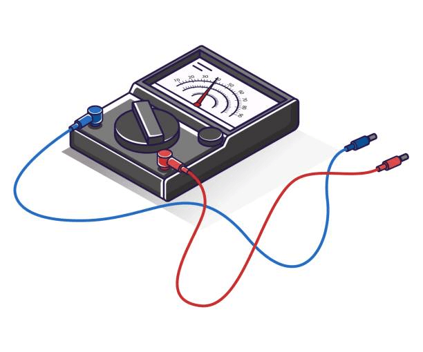
Figure 1: Analog Multimeter
Differences Between Analog and Digital Multimeters
Analog Ohmmeters
Analog ohmmeters are tools used for measuring resistance in electrical parts and circuits. To use an analog ohmmeter, you first set the function switch to measure ohms (Ω). Then, adjust the selector switch to one of the range settings like Ω, R × 1, R × 100, R × 1K, or R × 10,000. These settings allow the ohmmeter to measure different levels of resistance, making it useful for various tasks.
The ohmmeter uses its internal batteries to take resistance measurements, so the condition of the batteries matters a lot. If the batteries are not in good condition, the measurements might not be accurate. To make sure the readings are correct, you need to zero the pointer on the meter before taking any measurements.
Zeroing the pointer means connecting the two test leads of the ohmmeter together, creating a circuit with no resistance. After connecting the leads, you turn the zero adjuster control knob until the pointer is exactly at the 0 Ω mark on the scale. This step sets the ohmmeter correctly for the current battery condition, ensuring accurate readings.
You need to repeat the zeroing process every time you change the function switch or selector switch to a different range. This is because different ranges may use different amounts of power from the internal batteries, which can slightly change their voltage. By re-zeroing the pointer after each range change, you make up for any changes in battery output, keeping the measurements precise.
For example, if you first set the selector switch to R × 1 and zero the meter, and then switch to R × 100, you must zero the meter again. This ensures that the meter shows the correct resistance without being affected by any changes in the battery condition.
Digital Ohmmeters
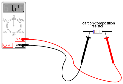
Figure 2: Digital Multimeter Measuring the Resistance of a Carbon-Composition Resistor
Digital ohmmeters are tools for measuring electrical resistance and work with internal batteries. To use a digital ohmmeter, set it to the resistance measurement mode, shown by the Ω symbol. This step ensures the meter is ready to measure resistance.
To zero a digital ohmmeter, follow these steps:
1.Set the function switch to the resistance measurement (Ω) position. This step prepares the meter for accurate readings.
2.Touch the two test leads together. This action lets the meter read the resistance of the leads themselves.
Some digital ohmmeters automatically zero out the lead resistance, showing a reading of 0 Ω. Others display the actual resistance of the test leads, usually between 0.2 Ω and 0.5 Ω.
If the ohmmeter shows the resistance of the test leads, you need to zero it manually. Press the relative mode (REL) button on the digital ohmmeter. This button adjusts the meter to remove the lead resistance, setting the device to zero. This step ensures accurate resistance measurements, especially with low-resistance components where even a small lead resistance could significantly affect the reading.
The zeroing process, whether automatic or manual, ensures that the meter is correctly calibrated for precise resistance measurements. This calibration is necessary for reliable and accurate results in various tasks, from simple circuit testing to more complex diagnostics.
Digital ohmmeters have clear, easy-to-read displays and often come with features like automatic ranging. This feature selects the right measurement range for the resistance being tested, making the process simpler and reducing user errors. These benefits make digital ohmmeters user-friendly and effective for both beginners and experienced users.
Ohmmeter Applications
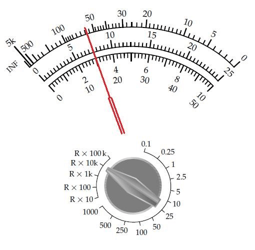
Figure 3: Analog Multimeter Reading a Resistance
Ohmmeter measurements are useful for determining the resistance of circuits or components. They help diagnose and identify the type and condition of various electrical parts. By measuring resistance, ohmmeters can provide valuable information about the operational status and integrity of electrical systems.
One practical application of ohmmeter measurements is in identifying the wiring setup of electric motors, such as a 9-lead, 3-phase (3ϕ) motor. These motors can be wired in either a wye (Y) or delta (Δ) configuration. An ohmmeter can help distinguish between these two configurations by measuring the resistance between different leads. In a wye configuration, the resistance readings between certain leads will differ from those in a delta configuration due to the distinct wiring patterns.
Ohmmeters are also used in testing the condition of motor windings. Motor windings can develop faults such as open or short circuits, which significantly impact motor performance. An open winding occurs when the circuit is interrupted, which is typically displayed on an ohmmeter as an overload (OL) or infinite resistance. This indicates that there is a break in the winding, preventing electrical current from flowing through it. On the other hand, a shorted winding occurs when there is an unintended connection between two points in the winding, resulting in a resistance reading of 0 Ω or a lower-than-normal value. This condition can cause excessive current flow, leading to overheating and potential motor failure.
To effectively use an ohmmeter for these purposes, it is important to follow proper measurement procedures. Ensure the circuit or component is de-energized before taking measurements, as voltage present in the circuit can cause inaccurate readings or damage the ohmmeter. Connect the test leads across the component or circuit under test, ensuring good contact and clean connections to avoid erroneous readings. The resistance value displayed by the ohmmeter can then be interpreted to assess the condition and configuration of the component.
Ohmmeter Measurement Procedures
Figure 4: Digital Multimeter Set to Measure Resistance in a Circuit
Ensuring Compatibility and Safety
Before taking any resistance measurements with an ohmmeter, make sure the meter is designed for the specific circuit you are testing. Check the test instrument's operating manual to understand all precautions, restrictions, and procedures. Always follow safety rules and wear the required protective gear to avoid accidents and ensure accurate readings.
Verifying Power is Off
Ensure all power is off to the circuit you are testing. This is needed for both safety and accuracy. Live circuits can damage the ohmmeter and give incorrect readings. Remove the component being tested from the circuit to completely isolate it and avoid interference from other parts.
Setting to Resistance Mode
Set the ohmmeter's function switch to the resistance mode, usually indicated by the symbol Ω. For digital ohmmeters, this is usually simple and involves selecting the mode. Analog ohmmeters require choosing the right range, such as R × 1, R × 100, or R × 1K, depending on the expected resistance value.
Connecting Test Leads
Connect the test leads properly to ensure accurate measurement. Plug the black test lead into the common jack and the red test lead into the resistance jack. This correct setup is needed for the meter to work accurately.
Checking Battery Condition
Check the condition of the batteries in the ohmmeter. Most digital meters will show a battery symbol if the batteries are low. Low batteries can affect the accuracy of readings. Replace batteries if needed to ensure the meter works correctly and provides accurate measurements.
Zeroing the Ohmmeter
Zero the ohmmeter to account for any resistance in the test leads. Connect the test leads together. For digital ohmmeters, the display should read 0 Ω, or the resistance of the test leads (typically between 0.2 Ω and 0.5 Ω). If the meter shows the resistance of the test leads, use the relative mode (REL) button to zero the meter. For analog meters, adjust the zero adjuster control knob until the pointer indicates 0 Ω. This step must be performed each time the range or function switch position is changed.
Connecting Test Leads to Component
Ensure proper contact between the test leads and the component being tested. Poor contact can lead to incorrect readings. Dirt, solder flux, oil, and other contaminants can significantly affect the resistance measurements. Avoid touching the metal ends of the test leads during measurement, as this can add extra resistance from your fingers, leading to incorrect readings.
Reading the Measurement
Once the test leads are connected to the component, read the resistance measurement displayed on the ohmmeter. For digital meters, this will be a straightforward numerical readout. For analog meters, ensure you read the correct scale matching the selected range, and eliminate any parallax error by viewing the needle head-on.
Completing the Measurement
After completing all resistance measurements, remove the ohmmeter from the circuit or component. Turn off the meter to prevent battery drain. Properly store the test instrument to maintain its accuracy and longevity.
Precautions When Using an Ohmmeter
To keep your ohmmeter working well and lasting longer, always use batteries approved by the manufacturer. These recommended batteries help maintain the device's accuracy. Before putting in new batteries, clean the contacts on both the batteries and the battery holders in the device. This cleaning removes any dirt or corrosion that could affect the electrical connection, ensuring the ohmmeter works properly and gives accurate readings. When inserting the new batteries, make sure to follow the polarity markings on the device. These markings show the correct way to place the batteries. Incorrect placement can damage the device or cause it to malfunction, leading to inaccurate readings or stopping the ohmmeter from working. Replace all the batteries at the same time, even if only one seems low. This ensures consistent power levels, which are necessary for accurate measurements. Uneven power can cause fluctuations in readings. Dispose of old batteries properly. Batteries contain harmful materials that can damage the environment if not disposed of correctly. Follow local rules for battery disposal to protect the environment. By using approved batteries, cleaning contacts, ensuring correct polarity, replacing all batteries together, and disposing of old batteries properly, you can keep your ohmmeter accurate and reliable. This ensures it performs well for all resistance measurements.
Reading Resistance Scale on an Analog Multi-tester
Reading resistance on electronic parts with an analog multi-tester requires knowing the resistance scale, which is usually at the top of the meter panel. This scale is read from right to left, starting at zero and going up to infinity (∞). The scale is divided into parts, each showing specific resistance values, which are not equally spaced.
For example, the part from 0 to 1 ohm is divided into five smaller steps, each showing 0.2 ohms. As you move from 1 to 2 ohms, the steps are still 0.2 ohms each, making it easy to read small resistance values accurately. The part between 2 and 5 ohms is divided into six steps, each showing 0.5 ohms, allowing for more detailed readings in this range. The part from 5 to 10 ohms is divided into ten steps, each showing 0.5 ohms, keeping the detailed measurement ability.
As the resistance values get higher, the divisions change. For example, from 10 to 20 ohms, each step shows 1 ohm. From 20 to 30 ohms, each step shows 2 ohms. This pattern continues, with each part adjusted to give a clear and accurate reading across a wide range of resistances.
When measuring resistance, start by zeroing the meter. This means connecting the test leads together and adjusting the zero adjuster knob until the pointer reads zero ohms. This step makes sure the meter accounts for any internal resistance from the leads themselves. Once zeroed, you can measure the resistance of the part or circuit.
Connect the test leads to the part, making sure of good contact to avoid any extra resistance that could change the reading. The needle on the meter will move to show the resistance value, which you then read from the right scale based on the range setting. It is important to avoid touching the metal ends of the test leads with your fingers during the measurement, as this can add extra resistance and affect the results.
Knowing the scale and the importance of accurate zeroing allows for precise measurements, whether you are working with low or high resistance values. Understanding the scale divisions and practicing will help you quickly and accurately determine the resistance of different electronic parts, ensuring reliable and consistent readings.
Scale Divisions and Multiplier Ranges:
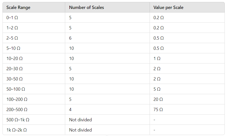
Figure 5: Table Showing Scale Divisions for Resistance Measurements
For measuring higher resistance, change the ohmmeter setting to a higher multiplier range.
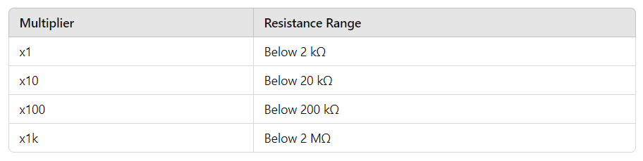
Figure 6: Table Showing Resistance Range Multipliers and their Corresponding Resistance Ranges
Example of Using Ohmmeter - Resistance Measurement
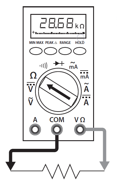
Figure 7: Learning resistance measurement using a digital multimeter
Learning to measure resistance accurately involves understanding the basics and using an ohmmeter correctly. Whether using an analog or digital ohmmeter, it's important to start with the circuit or component turned off to avoid wrong readings and potential damage to the meter.
For analog ohmmeters, first set the function switch to ohms and select the right range. Zero the meter by connecting the test leads together and adjusting the zero adjuster control knob until the pointer is on 0 Ω. For digital ohmmeters, set the function switch to the resistance measurement mode and zero the meter by touching the test leads together. This will eliminate the resistance of the leads.
Make sure the test leads have good contact with the component. Dirt or other contaminants can affect readings. Clean connections are needed, and you should avoid touching the metal ends of the test leads with your fingers. Read the resistance value displayed on the meter. For analog meters, look straight at the needle to avoid parallax error. Use the correct range for accurate readings.
Practicing with different components, such as resistors, transistors, and diodes, helps you understand resistance measurements better. Resistors have color codes indicating their value, which should match the measurement. Transistors and diodes have specific resistance characteristics for checking their condition. Regular practice and using the right techniques will help you measure resistance accurately while following safety precautions and consulting the test instrument's manual for detailed guidelines.
How to Read an Ohm Meter?
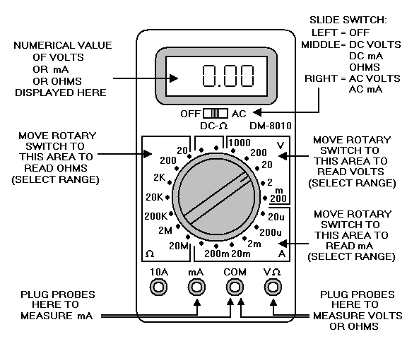
Figure 8: Labeled Diagram of a Digital Multimeter
An ohm meter, often combined into a multimeter (volt-ohm-milliammeter or VOM), measures electrical resistance. Resistance is how much a component or circuit resists the flow of electric current. There are two main types of ohm meters: the D'Arsonval type, which has a needle display, and the digital multimeter (DMM) type, which has an LCD display.
To accurately read an ohm meter, follow these steps:
First of all, attach the leads. Begin by connecting the leads of the ohm meter to the component whose resistance you want to measure. The ohm meter typically comes with two leads, one red and one black. For resistance measurement, it does not matter which lead goes where, so you can attach them in any order. Ensure a good mechanical connection, meaning the leads should firmly contact the component without any loose connections. This ensures accurate measurements and avoids fluctuating readings.
Next, set the range. Turn on the ohm meter. Analog ohm meters often have a switch on the front or side for power. Once powered on, set the meter to the resistance measurement mode, usually shown by the Greek letter Omega (Ω), the symbol for ohms. If you do not know the expected resistance value of the component, it is a good idea to start with the highest range setting. This prevents potential overload or damage to the meter. For digital ohm meters, you can adjust the range by turning the dial or using the range buttons until you get a reading within the meter's scale.
Finally, read the display. For analog (D'Arsonval) ohm meters, the needle will move across a scale to show the resistance. Make sure you are looking at the meter straight on to avoid parallax error, which happens when the needle and its reflection do not align, causing incorrect readings. The scale may have multiple ranges, so be sure to read the value corresponding to the range setting you've selected. The needle's position will indicate the resistance in ohms (Ω), kilo-ohms (kΩ), or mega-ohms (MΩ). For digital multimeters (DMMs), reading the value is easier. The resistance value will be displayed directly on the LCD screen, making it easy to read without interpreting needle positions or scale lines. If the displayed value flashes or shows "OL" (over limit), this means the resistance is higher than the current range setting. In such cases, adjust the range to a higher setting until you get a stable reading.
Practical Tips for Accurate Readings
To get accurate readings with an ohm meter, make sure the component you are measuring is completely turned off and not connected to any power source. This step prevents incorrect readings and protects the meter from damage. Always double-check that the component is not connected to any power supply before you start measuring.
When you measure resistance, the leads (the wires you connect to the component) should be clean. Dirt, oil, or other substances on the leads can cause bad contact and give you incorrect readings. Clean leads ensure that the connection is good and the measurement is accurate.
For components with very low resistance, even the small resistance of the test leads themselves can affect the measurement. This happens because the resistance in the leads can be noticeable when you are measuring very low values. Many digital ohm meters have a special button called the relative mode (REL) button. This button helps you get a more accurate measurement by canceling out the resistance of the test leads. When you press the REL button, the meter sets the lead resistance to zero, so it only measures the resistance of the component itself. This feature helps you get a more precise reading.
Conclusion
Accurate ohmmeter readings are very useful for diagnosing and working with electrical parts. Understanding the differences between analog and digital ohmmeters, following the correct measurement steps, and ensuring good contact and clean connections are all key to getting reliable results. Zeroing the meter correctly, whether analog or digital, ensures precise measurements. Features like the relative mode (REL) button on digital meters can help remove the resistance of the test leads, leading to more accurate readings. By following these guidelines and practicing regularly, you can become skilled in using ohmmeters, ensuring accurate and consistent measurements for all your electrical testing needs.
Frequently Asked Questions [FAQ]
1. What is the ohmmeter method of measuring resistance?
The ohmmeter method of measuring resistance involves using an ohmmeter to find out the resistance of a part or circuit with no power. Connect the test leads of the ohmmeter to the part, making sure the device is set to the correct resistance range. The ohmmeter sends a small current through the part and measures the voltage drop to calculate the resistance.
2. How to read the ohmmeter scale properly?
To read the ohmmeter scale properly, first make sure the meter is set to zero by connecting the test leads together and adjusting the zero knob if needed. For analog meters, read the value where the needle points on the scale, making sure your eye is level with the needle to avoid errors. For digital meters, simply read the number shown on the screen.
3. What is a normal ohm reading?
A normal ohm reading depends on the part being measured. For most household resistors, values can range from a few ohms to several million ohms (megaohms). Always compare the reading to the expected value given for the part.
4. How do you know your ohmmeter is working correctly?
You know your ohmmeter is working correctly by testing it with a resistor that has a known value. If the meter shows the correct resistance for this resistor, it is working properly. Also, make sure the battery is good and the meter is set to zero correctly.
5. What is a good resistance reading?
A good resistance reading depends on the context. For a simple resistor, it should match the expected value within a certain range. For a motor winding or cable, a low reading (near zero) means a short circuit, while a very high reading (infinite resistance) means an open circuit. In most cases, a good reading is close to the expected resistance of the part being tested.