MPU-6050 in Action: Practical Guide to Setup, Configuration, and Noise Management
Catalog
Introduction to MPU-6050
MPU-6050 is the world's first integrated 6-axis motion processing component, which integrates a 3-axis gyroscope, 3-axis accelerometer, and a scalable digital motion processor (DMP). The purpose of using it is to obtain the inclination angle of the object to be measured (such as a quadcopter, a balancing car) on the x, y, and z axes, that is, the pitch angle, roll angle, and yaw angle. We read the six data of the MPU-6050 (three-axis acceleration AD value and three-axis angular velocity AD value) through the I2C interface. After posture fusion processing, the Pitch, Roll, and Yaw angles can be calculated. As a directional reference for measurement values, the definition of the sensor coordinate direction is as shown in the figure below, which follows the principle of the right-handed coordinate system (that is, the right thumb points to the positive direction of the x-axis, the index finger points to the positive direction of the y-axis, and the middle finger points to the positive direction of the z-axis).
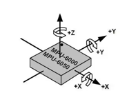
With its dedicated I2C sensor bus, the MPU-6050 is able to receive input directly from an external 3-axis compass, providing a full 9-axis MotionFusion™ output. It eliminates the discrepancy problem between the combined gyroscope and accelerator timeline and significantly reduces packaging space compared to multi-component solutions. When connected to a three-axis magnetometer, the MPU-60X0 is capable of providing full 9-axis motion fusion output to its main I2C or SPI port (note that the SPI port is only available on the MPU-6000).
Alternatives and Equivalents
• MPU-3300
• MPU-6000
• MPU-6500
Manufacturer of MPU-6050
The manufacturer of MPU-6050 is TDK. After the two founders of TDK, Dr. Yogoro Kato and Takei Takei, invented ferrite in Tokyo, they founded Tokyo Denkikagaku Kogyo K.K. in 1935. As a global electronics industry brand, TDK has always maintained a dominant position in the fields of electronic raw materials and electronic components. TDK's comprehensive and innovation-driven product portfolio covers passive components such as ceramic capacitors, aluminum electrolytic capacitors, film capacitors, magnetic products, high-frequency components, piezoelectric and protection devices, as well as sensors and sensor systems (such as temperature and pressure, magnetic and MEMS sensors), etc. In addition, TDK also provides power supplies and energy devices, magnetic heads and other products. Its product brands include TDK, EPCOS, InvenSense, Micronas, Tronics, and TDK-Lambda.
Internal Block Diagram of MPU-6050
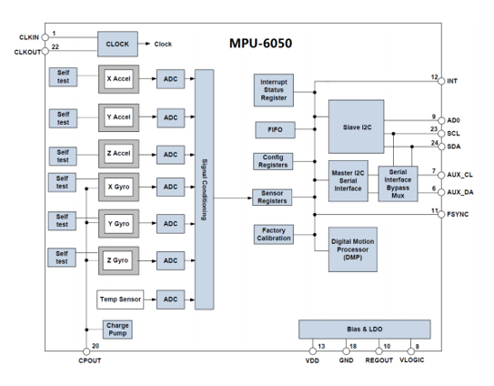
Among them, SCL and SDA are the IIC interfaces connected to the MCU, and the MCU controls the MPU-6050 through this IIC interface. There is also an IIC interface, namely AUX_CL and AUX_DA. This interface can be used to connect external slave devices, such as magnetic sensors, to form a nine-axis sensor. VLOGIC is the IO port voltage. This pin can support a minimum of 1.8V. We usually connect it directly to VDD. AD0 is the address control pin of the slave IIC interface (connected to the MCU). This pin controls the lowest bit of the IIC address. If it is connected to GND, the IIC address of MPU-6050 is 0x68; if it is connected to VDD, it is 0x69. Please note that the address here does not include the lowest bit of data transmission (the lowest bit is used to represent read and write operations). On the MWbalancedSTC15, AD0 is connected to GND, so the IIC address of the MPU-6050 is 0x68 (excluding the lowest bit).
Initialize the IIC Interface
MPU-6050 uses IIC to communicate with STC15, so we need to initialize the SDA and SCL data lines connected to MPU-6050 first.
Reset MPU-6050
This step restores all registers inside the MPU-6050 to their default values, which is achieved by writing 1 to bit 7 of the power management register 1 (0x6B). After reset, the power management register 1 will be restored to the default value (0x40), and this register must subsequently be set to 0x00 to wake up the MPU-6050 and put it into a normal working state.
Set the Full-Scale Range of the Angular Velocity Sensor (Gyro) and Acceleration Sensor
In this step, we set the full-scale range (FSR) of the two sensors through the gyroscope configuration register (0X1B) and the acceleration sensor configuration register (0X1C) respectively. Typically, we set the full-scale range of the gyroscope to ±2000dps and the full-scale range of the accelerometer to ±2g.
Set Other Parameters
Here, we also need to configure the following parameters: turn off interrupts, disable the AUX I2C interface, disable FIFO, set the gyroscope sampling rate, and configure the digital low-pass filter (DLPF). Since we do not use interrupts to read data in this chapter, the interrupt function needs to be turned off. At the same time, since we are not using the AUX I2C interface to connect other external sensors, we also need to close this interface. These functions can be controlled through the interrupt enable register (0x38) and user control register (0x6A). MPU-6050 can use FIFO to store sensor data, but we have not used it in this chapter, so all FIFO channels need to be closed. This can be controlled through the FIFO enable register (0x23). By default, the value of this register is 0 (that is, FIFO is disabled), so we can use the default value directly. The sampling rate of the gyroscope is controlled by the sampling rate divider register (0x19). Normally, we set this sampling rate to 50. The configuration of the digital low-pass filter (DLPF) is completed through the configuration register (0x1A). Generally speaking, we will set DLPF to half the bandwidth to balance data accuracy and response speed.
Configure the System Clock Source and Enable the Angular Velocity Sensor and Acceleration Sensor
The setting of the system clock source depends on the power management register 1 (0x6B), where the lowest three bits of this register determine the selection of the clock source. By default, these three bits are set to 0, which means the system uses the internal 8MHz RC oscillator as the clock source. However, in order to improve the clock accuracy, we often set it to 1 and select the x-axis gyroscope PLL as the clock source. In addition, enabling the angular velocity sensor and acceleration sensor is also an important step in the initialization process. Both operations are implemented through power management register 2 (0x6C). Simply set the corresponding bit to 0 to activate the corresponding sensor. After completing the above steps, the MPU-6050 can enter normal working status. Those registers that are not specially set will adopt the default values preset by the system.
How Does the MPU-6050 Work?
Gyro Sensor
The sensor is equipped with a gyro inside, which will always remain parallel to the initial direction due to the gyroscopic effect. Therefore, we can calculate the direction and angle of rotation by detecting the deviation of the gyro from the initial direction.
Accelerometer Sensor
An accelerometer sensor is a device that can measure acceleration and it works based on the principle of the piezoelectric effect. During acceleration, the sensor measures the inertial force applied to the mass block and then calculates the acceleration value using Newton's second law.
Digital Motion Processor (DMP)
The DMP is a data processing module in the MPU6050 chip that has a built-in Kalman filtering algorithm for acquiring data from the gyroscope and accelerometer sensors and processing the output quaternions. This feature greatly reduces the workload of the peripheral microprocessor and avoids the tedious filtering and data fusion process.
Notes:
Quaternions: Quaternions are simple supercomplex numbers. Complex numbers are composed of real numbers plus the imaginary unit i, where i^2 = -1.
Where is MPU-6050 Used?
• Toys
• Handset and portable gaming
• Motion-based game controllers
• BlurFree™ technology (for video/still image stabilization)
• AirSign™ technology (for security/authentication)
• InstantGesture™ iG™ gesture recognition
• Wearable sensors for health, fitness and sports
• Motion-enabled game and application framework
• MotionCommand™ technology (for gesture short-cuts)
• Location-based services, points of interest, and dead reckoning
• 3D remote controls for Internet-connected DTVs and set-top boxes, 3D mice
• TouchAnywhere™ technology (for “no touch” UI application control/navigation)
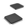
Package of MPU-6050
How to Reduce the Noise of MPU-6050?
We can take the following ways to reduce the noise of MPU-6050:
Use Calibrated Sensors: Calibrating the accelerometer and gyroscope of the MPU-6050 can eliminate the bias and error of the sensors themselves, thus reducing the effect of noise. The calibration process usually consists of two stages: static calibration and motion calibration.
Hardware Filtering Process: Adding filter capacitors to the power line of MPU-6050 can reduce the impact of power supply noise on the sensor. Meanwhile, during PCB layout, we should try to keep MPU-6050 away from potential sources of interference, such as high-frequency signal lines and high-power components.
Software Filtering Processing: After collecting the raw data from MPU-6050, we can add a software filtering link to pre-process the initial data to eliminate noise-induced interference. Commonly used software filtering methods include mean filtering, median filtering, Kalman filtering and so on.
Use Internal Low-Pass Filter: MPU-6050 has an internal integrated digital low-pass filter, which can be used to reduce high-frequency noise by setting its cutoff frequency. Specifically, we can set the cutoff frequency of the digital filter by modifying the CONFIG register of the MPU-6050 to eliminate the high-frequency noise caused by A/D sampling.
MPU-6050-Based Motion Trajectory Calculation
The MPU-6050 is a six-axis accelerometer and gyroscope sensor that can be used to measure the motion and attitude of objects. The motion trajectory calculation based on MPU-6050 can be realized by the following steps:
The First Step is to Read the Sensor Data. We need to read the accelerometer and gyroscope data from the MPU-6050 sensors using appropriate drivers and library functions. These data are usually output in a digital format, so some conversion and calibration work is required to convert them to actual measurements in physical units.
The Second Step is to Calculate the Acceleration. First, we need to process the data from the accelerometer to derive the acceleration of the object in each axis. Subsequently, in order to calculate the velocity and displacement of the object in each axis, we need to integrate the acceleration data. Numerical integration techniques, such as Euler's method or the Lunger-Kutta method, are often used in this process to ensure the accuracy of the displacement calculations.
The Third Step is to Calculate the Angular Velocity. Using gyroscope data, the angular velocity of the object in each axis can be calculated. Again, this data needs to be calibrated and converted to obtain the angular velocity in actual physical units.
The Fourth Step is to Calculate the Rotation. By integrating the angular velocity data, the angle of rotation of the object in each axis can be calculated. This can be done using numerical integration techniques such as Euler's method or the Longe-Kutta method to calculate the angle.
The Fifth Step is to Merge the Data. We combine the data from accelerometers and gyroscopes to obtain complete attitude and position information of the object. This can be done using algorithms such as quaternion-based attitude solver or Euler angle solver.
The Sixth Step is to Visualize the Results. We convert the computed object motion trajectory into a set of points in a 3D coordinate system and display it using appropriate visualization tools for a more intuitive understanding of the object's motion trajectory and attitude changes.
Frequently Asked Questions [FAQ]
1. How accurate is MPU6050?
The acquired results showed sufficient accuracy of less than 1 % and reliability, assuring the proper dimensioning of the elevator shaft and the high standards of the lift industry.
2. How to read data from MPU6050?
To read the internal MPU6050 registers, the master sends a start condition, followed by the I2C slave address and a write bit, and then the register address that is going to be read.
3. Where is MPU6050 used?
In wearable health-tracking, fitness-tracking devices. In drones and quadcopters, MPU6050 is used for position control. Used in controlling Robotic Arm. Hand gesture control devices.
4. Is MPU6050 an IMU?
The MPU6050 IMU Sensor block reads data from the MPU-6050 sensor that is connected to the hardware. The block outputs acceleration, angular rate, and temperature along the axes of the sensor.
5. What is the processing of MPU6050?
This is the MPU6050's onboard processor that combines the data coming from the accelerometer and gyroscope. The DMP is the key to using the the MPU6050 and is explained in detail later. As with all microprocessors the DMP needs firmware in order to run.
About us
ALLELCO LIMITED
Read more
Quick inquiry
Please send an inquiry, we will respond immediately.
In-Depth Guide to LM317: Understanding Adjustable Voltage Regulators
on September 3th
Understanding the TL431: A Comprehensive Guide to Precision Shunt Regulators
on September 3th
Popular Posts
-

What is GND in the circuit?
on January 1th 3092
-

RJ-45 Connector Guide: RJ-45 Connector Color Codes, Wiring Schemes, R-J45 Applications, RJ-45 Datasheets
on January 1th 2661
-

Understanding Power Supply Voltages in Electronics VCC, VDD, VEE, VSS, and GND
on November 14th 2185
-

Fiber Connector Types: SC Vs LC And LC Vs MTP
on January 1th 2175
-

Comparison Between DB9 and RS232
on January 1th 1799
-

What Is An LR44 Battery?
Electricity, that ubiquitous force, quietly permeates every aspect of our daily lives, from trivial gadgets to life-threatening medical equipment, it plays a silent role. However, truly grasping this energy, especially how to store and efficiently output it, is no easy task. It is against this background that this article will focus on a type of coin cell battery that may seem insignificant on the...on January 1th 1773
-

Understanding the Fundamentals:Inductance Resistance, andCapacitance
In the intricate dance of electrical engineering, a trio of fundamental elements takes center stage: inductance, resistance, and capacitance. Each bears unique traits that dictate the dynamic rhythms of electronic circuits. Here, we embark on a journey to decipher the complexities of these components, to uncover their distinct roles and practical uses within the vast electrical orchestra. Inductan...on January 1th 1726
-

CR2430 Battery Comprehensive Guide: Specifications, Applications and Comparison to CR2032 Batteries
What is CR2430 battery ?Benefits of CR2430 BatteriesNormCR2430 Battery ApplicationsCR2430 EquivalentCR2430 VS CR2032Battery CR2430 SizeWhat to look for when buying the CR2430 and equivalentsData Sheet PDFFrequently Asked Questions Batteries are the heart of small electronic devices. Among the many types available, coin cells play a crucial role, commonly found in calculators, remote controls, and ...on January 1th 1667
-

What Is RF and Why Do We Use It?
Radio Frequency (RF) technology is a key part of modern wireless communication, enabling data transmission over long distances without physical connections. This article delves into the basics of RF, explaining how electromagnetic radiation (EMR) makes RF communication possible. We will explore the principles of EMR, the creation and control of RF signals, and their wide-ranging uses. The article ...on January 1th 1665
-
Comprehensive guide to hFE in transistors
Transistors are crucial components in modern electronic devices, enabling signal amplification and control. This article delves into the knowledge surrounding hFE, including how to select a transistor's hFE value, how to find hFE, and the gain of different types of transistors. Through our exploration of hFE, we gain a deeper understanding of how transistors work and their role in electronic circu...on November 14th 1616


