In-Depth Guide to LM317: Understanding Adjustable Voltage Regulators
LM317 is one of the most widely used power integrated circuits. It not only has the simplest form of a fixed three-terminal voltage regulator circuit, but also has the characteristics of adjustable output voltage. In addition, it also has the advantages of low noise, wide voltage regulation range, good voltage stabilization performance, and high ripple suppression ratio. In this article, we will discuss some key points related to LM317 so that you can have an in-depth understanding of this device. So let’s get started!Catalog
Introduction to LM317
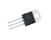
The LM317 is a three-terminal adjustable positive voltage regulator IC from National Semiconductor. The LM317 has a wide output voltage range of 1.2V to 37V and a load current of up to 1.5A. Using the LM317 is very simple, requiring only two external resistors to set the desired output voltage. In addition, the LM317 offers better linearity and load regulation than standard fixed regulators, and a variety of protection circuits are integrated into the LM317 to ensure stable and reliable operation, including overload protection and safe zone protection. Normally, the LM317 does not require external capacitors, but if the connection from the input filter capacitor to the LM317 input is more than 6 inches (about 15 cm), external capacitors are recommended. The use of output capacitors also improves the transient response. If we use a filter capacitor on the adjustment side, we can obtain a ripple rejection ratio much higher than that of a standard three-terminal regulator.
The LM317 has several special uses. For example, by suspending the regulator at a higher voltage, the LM317 can regulate voltages up to several hundred volts, provided that the input or output voltage difference does not exceed its limits and that short circuits at the outputs are avoided. Additionally, we can connect the adjusting terminal to a programmable voltage for programmable power output functionality.
Alternatives and Equivalents
• LM7905
• LM7809
• LM7912
• LT1086
The Function of LM317 Adjustable Voltage Stabilized Power Supply Voltage Stabilizing Circuit
LM317 adjustable voltage regulator voltage regulator circuit is the main role of the input voltage is stably converted to the required output voltage, so as to provide a stable and reliable power supply for the circuit or device. Specifically, the role of the voltage regulator circuit is as follows:
Provide reliability: The design of voltage regulator circuits usually takes into account over-current protection, over-temperature protection, short-circuit protection and other functions to ensure the safe operation of circuits and equipment. These protection mechanisms ensure the reliability and stability of the regulated power supply in unexpected situations.
Adjust the output voltage: The voltage regulator circuit allows the user to adjust the output voltage as needed to suit different circuit requirements. By simply adjusting the potentiometer or resistor, the desired output voltage can be realized within a certain range.
Protect load devices: A voltage regulator circuit protects load devices from input voltage variations by stabilizing the output voltage. It can resist power fluctuations and noise interference and prevent damage to the load equipment caused by too high or too low voltage.
Provide stable voltage: The voltage regulator circuit is able to automatically adjust and stabilize the output voltage according to the changes of input voltage and load current through the feedback control mechanism. In this way, the voltage regulator circuit can provide constant output voltage under different load conditions to ensure the normal operation of the powered equipment.
Soft-Start Circuit of LM317
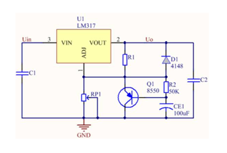
The figure below shows a soft-start circuit built using LM317. At the moment of power-on, since the voltage on CE1 cannot change suddenly, Q1 is saturated and turned on through the bias effect of R1 and R2. This conduction state causes RP1 to be shorted, causing the adjustment terminal of the LM317 to ground. At this time, the output voltage of the power supply is 1.25V. As the charging time of C2 increases, the output voltage will gradually increase. The function of D1 is to quickly release the charge on C2 after the power is turned off to ensure that the soft start can be achieved normally when the power is turned on next time. In addition, it should be noted that if Q1 and R2 are not connected, but a large electrolytic capacitor is connected in parallel to both ends of RP1, the soft start effect can also be achieved.
Minimum Stable Operating Current of LM317
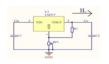
The LM317 voltage regulator block has a minimum stable operating current, sometimes also called the minimum output current or minimum discharge current. Typically, the value of this minimum stable operating current is approximately 1.5mA. Due to differences in manufacturers and models of the LM317 voltage regulator block, the specific value of the minimum stable operating current may also be different, but it generally does not exceed 5mA. When the output current of the LM317 voltage regulator block is lower than its minimum stable operating current, it will not work properly. On the contrary, when the output current exceeds this threshold, the LM317 voltage regulator block can output a stable DC voltage.
When making a regulated power supply based on the LM317 voltage regulator block (as shown in the figure), be sure to pay attention to its minimum stable operating current. If this point is ignored, the following abnormal phenomena may occur in the regulated power supply we produce.
Calculation of LM317 Output Voltage and Selection of Voltage Regulating Resistor
The output voltage Vout of LM317 is jointly determined by resistors R1 and RP1. The specific formula is Vout=1.25×(1+RP1/R1). Since there is a fixed voltage of 1.25V between the Vout terminal and the Adj terminal (adjustment terminal) of LM317, if the resistance of R1 remains unchanged, the current flowing through R1 will be a constant value. Since RP1 and R1 are connected in series, the output voltage can be changed by simply adjusting the resistance of RP1. It should be noted that the operating current of the internal circuit of LM317 is output from the Vout terminal, and this current is approximately 5mA. Therefore, the maximum resistance of R1 should not exceed 240Ω. If the value of R1 is too large, the operating current of the internal circuit of LM317 will not be fully output, which will cause the output voltage to be high and the stability to decrease. In practical applications, in order to obtain better performance, it is best to choose a metal film resistor with good temperature stability for R1. If the resistance temperature stability of R1 is not good, the output voltage of LM317 may drift.
Absolute Maximum Ratings of LM317

Why Does the Output Voltage of LM317 Change with the Input Voltage?
The voltage drop across the LM317 is determined by its internal resistance and the amount of current flowing through it. The internal resistance of the LM317 is typically between 0.2 and 0.6 ohms, this value will vary depending on the manufacturer and the specific device. When current flows through LM317, a voltage drop will occur on its internal resistance, which will affect the output voltage. In addition, the input voltage of LM317 will also affect its output voltage. Specifically, as the input voltage increases, the voltage drop across the internal resistance will increase accordingly, resulting in a decrease in the output voltage. On the contrary, if the input voltage decreases, the voltage drop across the internal resistance will also decrease, causing the output voltage to increase. In addition to the input voltage, the LM317's output voltage is also affected by temperature changes. As the temperature increases, the internal resistance of the LM317 increases, which reduces its output voltage. On the contrary, when the temperature decreases, the internal resistance of LM317 will decrease, thereby increasing its output voltage.
The effect of input voltage changes on the output voltage of the LM317 can be minimized by two methods. The first method is to use a preconditioner. The pre-regulator is a voltage regulator located before the LM317. Its function is to provide a stable voltage to the input of the LM317. There are many types of preregulators, which can be linear regulators, switching regulators, or Zener diodes. By providing a regulated voltage to the LM317, the preregulator can effectively reduce voltage fluctuations at the input of the LM317. When selecting a preregulator, we need to make a reasonable match based on the input voltage range of the LM317 and the expected output voltage. The second method is to use a bypass capacitor. The bypass capacitor is connected between the input and output of the LM317 and acts as a low-pass filter. It can effectively filter out high-frequency noise and voltage changes, which will affect the output voltage of LM317. The bypass capacitor provides a low-impedance path for high-frequency signals, preventing voltage changes from acting directly on the LM317. When selecting the value of the bypass capacitor, we need to consider the ripple of the input voltage and the size of the output current. Typically, the typical value of the bypass capacitor is between 1uF and 10uF.
Frequently Asked Questions [FAQ]
1. Is LM317 an op amp?
LM 317 is three terminal adjustable positive voltage regulator and not an operational amplifier and the minimum output is 1.2 volts.
2. What is a LM317 used for?
The LM317 serves a wide variety of applications including local, on card regulation. This device can also be used to make a programmable output regulator, or by connecting a fixed resistor between the adjustment and output, the LM317 can be used as a precision current regulator.
3. Is LM317 an LDO?
The LM317 Low Dropout (LDO) Linear Voltage Regulator is an adjustable 3-terminal positive LDO voltage regulator capable of supplying in excess of 1.5 A over an output voltage range of 1.2 V to 37 V. This voltage regulator is exceptionally easy to use and requires only two external resistors to set the output voltage.
4. What is the difference between LM1117 and LM317?
The main difference is dropout voltage. It is 1.2V for the lm1117 and about 3V for the LM317, so it depends upon the supply voltage that powers the regulator as to which one you can use. The LM1117 would require a minimum of 4.5V supply voltage (allowing operation from a standard 5V supply).
About us
ALLELCO LIMITED
Read more
Quick inquiry
Please send an inquiry, we will respond immediately.
Understanding SS34 Diodes: Uses, Advantages, and Key Specifications
on September 3th
MPU-6050 in Action: Practical Guide to Setup, Configuration, and Noise Management
on September 3th
Popular Posts
-

What is GND in the circuit?
on January 1th 3090
-

RJ-45 Connector Guide: RJ-45 Connector Color Codes, Wiring Schemes, R-J45 Applications, RJ-45 Datasheets
on January 1th 2660
-

Understanding Power Supply Voltages in Electronics VCC, VDD, VEE, VSS, and GND
on November 14th 2182
-

Fiber Connector Types: SC Vs LC And LC Vs MTP
on January 1th 2175
-

Comparison Between DB9 and RS232
on January 1th 1799
-

What Is An LR44 Battery?
Electricity, that ubiquitous force, quietly permeates every aspect of our daily lives, from trivial gadgets to life-threatening medical equipment, it plays a silent role. However, truly grasping this energy, especially how to store and efficiently output it, is no easy task. It is against this background that this article will focus on a type of coin cell battery that may seem insignificant on the...on January 1th 1772
-

Understanding the Fundamentals:Inductance Resistance, andCapacitance
In the intricate dance of electrical engineering, a trio of fundamental elements takes center stage: inductance, resistance, and capacitance. Each bears unique traits that dictate the dynamic rhythms of electronic circuits. Here, we embark on a journey to decipher the complexities of these components, to uncover their distinct roles and practical uses within the vast electrical orchestra. Inductan...on January 1th 1725
-

CR2430 Battery Comprehensive Guide: Specifications, Applications and Comparison to CR2032 Batteries
What is CR2430 battery ?Benefits of CR2430 BatteriesNormCR2430 Battery ApplicationsCR2430 EquivalentCR2430 VS CR2032Battery CR2430 SizeWhat to look for when buying the CR2430 and equivalentsData Sheet PDFFrequently Asked Questions Batteries are the heart of small electronic devices. Among the many types available, coin cells play a crucial role, commonly found in calculators, remote controls, and ...on January 1th 1667
-

What Is RF and Why Do We Use It?
Radio Frequency (RF) technology is a key part of modern wireless communication, enabling data transmission over long distances without physical connections. This article delves into the basics of RF, explaining how electromagnetic radiation (EMR) makes RF communication possible. We will explore the principles of EMR, the creation and control of RF signals, and their wide-ranging uses. The article ...on January 1th 1665
-
Comprehensive guide to hFE in transistors
Transistors are crucial components in modern electronic devices, enabling signal amplification and control. This article delves into the knowledge surrounding hFE, including how to select a transistor's hFE value, how to find hFE, and the gain of different types of transistors. Through our exploration of hFE, we gain a deeper understanding of how transistors work and their role in electronic circu...on November 14th 1615

