Mastering Relay Technology: Construction, Types, Working Principles, and Testing Methods
Relays are fundamental components in modern electrical systems, serving as the backbone for controlling circuits, protecting devices, and automating processes. At their core, relays are electromechanical switches that use an electrical signal to control the opening or closing of circuits. This essential function is achieved through the intricate interplay of various components, such as electromagnets, mechanical contacts, and switch points. The most common type, the electromagnetic relay, relies on magnetic forces generated by current passing through a coil, which then moves mechanical contacts to alter the state of the circuit. Understanding the detailed structure, types, working principles and practical applications of relays is beneficial for optimizing their use in various technical environments.Catalog
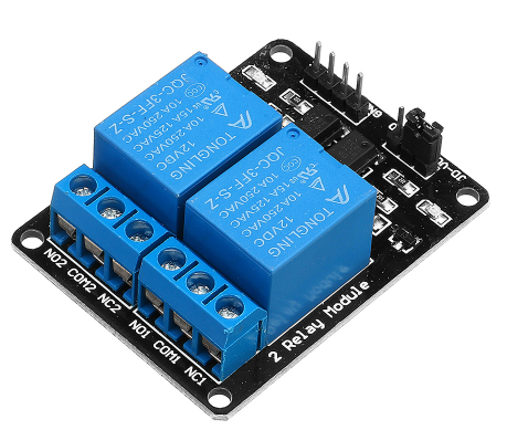
Figure 1: Relay
What Is a Relay?
A Relay is an electromechanical device that uses an electrical signal to open or close a circuit. This device utilizes the magnetic force generated by an electromagnet to attract or release mechanical contacts, altering the state of the circuit without manual intervention. There are various types of relays, with electromagnetic relays being the most common.
An electromagnetic relay consists primarily of several components: an electromagnet, mechanical contacts, switch points, and a reset spring. The electromagnet is created by winding copper wire around a metal core, with the ends of the coil connected to the relay's pins, usually the power pins. When an electric current passes through these coils, the electromagnet generates a magnetic force that moves the mechanical contacts, thereby connecting or disconnecting the circuit.
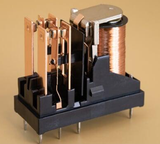
Figure 2: Electromagnetic Relay
These mechanical contacts move in response to the magnet's attraction or release, achieving the opening or closing of the circuit. The switch points handle high currents and include normally open (NO), normally closed (NC), and common (COM) contacts. The reset spring functions to return the contacts to their original position after the electromagnet is powered off, ensuring the circuit can return to its default state post-power outage.
Relays are applicable in both DC and AC circuits. In AC circuits, due to the periodic change in current, relays might lose magnetism when the current drops to zero, causing the circuit to open. To counteract this issue, AC relays often incorporate special designs, such as additional electronic circuits or shielded coils, to maintain continuous magnetism.
Relay design also takes into consideration enhancements in performance and reliability. For instance, the electromagnet’s coils use highly conductive materials and are designed in specific shapes and sizes to optimize magnetic strength and energy efficiency. Mechanical contacts and switch points are made from materials with high wear resistance and conductivity to ensure durability and reliability under frequent operation.
Solid-state relays use semiconductor materials to replace mechanical components, operating circuits through the control of semiconductor conduction and cutoff. These relays lack mechanical moving parts, resulting in faster response times and longer lifespans, making them ideal for applications requiring frequent switching.
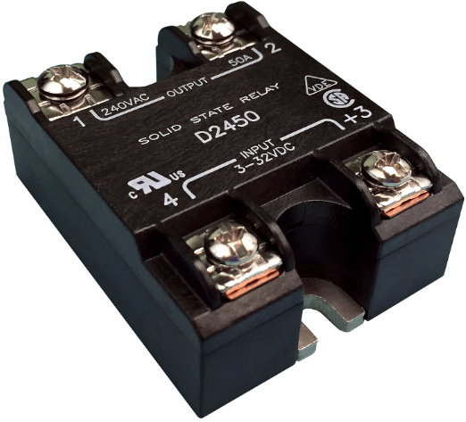
Figure 3: Solid-State Relay
Relays are widely used in industrial automation, household appliances, telecommunications equipment, and traffic control systems. They not only control circuit operations but also perform complex logic control and protection functions. As technology advances, relays continuously evolve in structure, materials, and control methods, significantly enhancing their performance and application value.
The Structure of the Relay
The construction of a relay involves several crucial parts: pins, coil, iron core, armature, reset spring, moving contact, and fixed contact. Let’s explore each component and how they work together in a typical operation。
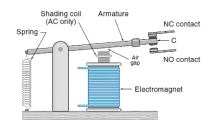
Figure 4: The Structure of the Electromagnetic Relay
Pins: Relays feature two types of pins—coil pins and switch pins. Switch pins include normally closed (NC), normally open (NO), and common (COM) contacts.
Coil and Iron Core: The heart of the relay is the coil, wrapped around an iron core. When an electric current flows through the coil, it generates a magnetic field around the iron core.
Armature: This is the movable part inside the relay. Activated by the magnetic field created when the coil is energized, the armature moves, altering the contact state between the moving and fixed contacts.
Reset Spring: Connected to the armature, the reset spring provides the necessary force to return the armature to its original position when the coil is de-energized.
Moving Contact: Attached to the armature, this contact shifts its position along with the armature. It either makes or breaks contact with the fixed contact depending on the state of the relay.
Fixed Contact: Fixed contacts are divided into NC and NO types. The NC contact remains closed when the relay is de-energized and opens when energized. Conversely, the NO contact is open when de-energized and closes upon energization.
In controlling a relay, it is common to use a wiring diagram featuring an NPN transistor, especially when control devices like an Arduino or integrated circuit cannot directly drive the relay. The base of the NPN transistor receives a current through a base resistor, activating the transistor. This allows current to flow from the collector to the emitter, powering the relay coil. When the transistor turns off, the collapsing magnetic field generates a voltage spike, which is mitigated by a flyback diode to protect the transistor.
For instance, an automatic streetlight circuit using a light-dependent resistor (LDR) and relays can be controlled via two NPN transistors. The resistance of the LDR increases in darkness and decreases during daylight, controlling the on-and-off states of the transistors. When the LDR detects reduced light levels (e.g., at night), its resistance increases, turning on the first transistor, followed by the second, thereby energizing the relay coil, closing the relay contacts, and turning on the streetlight. Conversely, when light levels increase (e.g., during the day), the LDR’s resistance decreases, and the transistors turn off, de-energizing the relay coil, opening the contacts, and turning off the streetlight.
This design ingeniously combines the characteristics of multiple components to control the operation of the light-sensitive resistor, transistors, and relay effectively. It not only enhances energy efficiency but also extends the lifespan of the streetlights and reduces maintenance costs. Such designs offer a deeper understanding of how relays function in practical applications and how their performance can be optimized to meet diverse requirements.
Types of Relays
Relays come in two main types: Solid-State Relays (SSRs) and Electromechanical Relays (EMRs). Each has distinct structural differences and performance capabilities that suit various applications.
Solid-State Relays (SSRs): SSRs operate without any moving parts, using semiconductor materials to switch circuits. This lack of mechanical parts allows for faster switching speeds and reduces mechanical wear, making SSRs ideal for applications requiring rapid response and high-frequency operation such as industrial automation and computer control systems.
Electromechanical Relays (EMRs): EMRs consist of movable mechanical parts and use electromagnetic force to open or close contacts. These moving parts can wear over time, and their response speeds may not match those of SSRs, which can be a limitation in certain applications.
EMRs are also incredibly diverse, each type tailored for specific scenarios:
Latching relays maintain their position until toggled and are ideal for applications requiring stable states, like memory backup or power cycling.
Reed relays, containing a reed switch within the coil, excel in high-speed switching environments such as communications equipment and testing instruments.
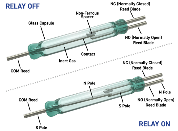
Figure 5: Reed Relays
Polarized relays are designed to prevent incorrect polarity connections, ensuring DC circuits operate correctly even when polarity is reversed.
High-frequency relays are made for reliable operation in high-frequency applications like wireless communication devices, where rapid switching is frequent.
Relays also vary based on switch configuration:
Single pole double throw (SPDT) relays, which include one common contact (COM), one normally closed (NC) contact, and one normally open (NO) contact, are commonly used in applications that require switching between two circuits.
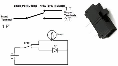
Figure 6: Single Pole Double Throw Relays
Single pole single throw (SPST) relays are simpler, with just one NO and one COM contact, suitable for basic on/off applications.
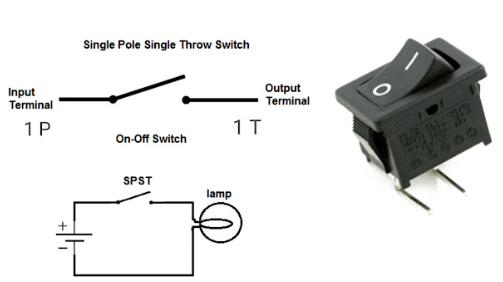
Figure 7: Single Pole Single Throw Relays
Double Pole Single Throw (DPST) relays have two sets of independent contacts, each controlling a separate circuit, useful for managing two independent circuits simultaneously.
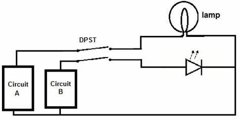
Figure 8: Double Pole Single Throw Relays
Double pole double throw (DPDT) relays, more complex, have two sets of contacts capable of switching two independent circuits each, widely used in systems needing intricate circuit switching.
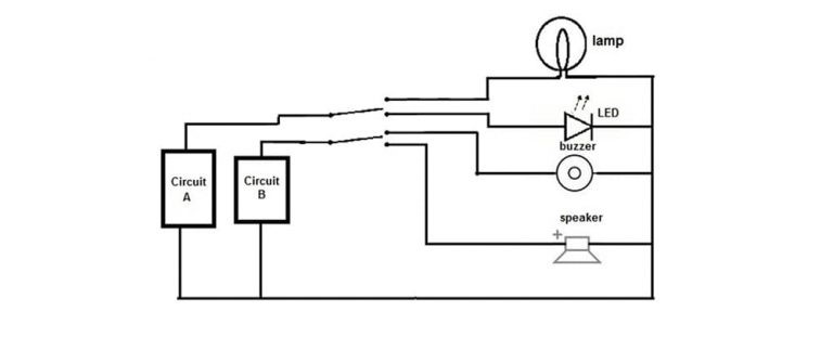
Figure 9: Double Pole Double Throw Relays
Beyond these, relays are categorized by function, structure, and application:
Electromagnetic relays are common, using electromagnetic forces to operate contacts.
Locking relays maintain their state even after power loss, suited for applications requiring status retention.
Electronic relays switch using electronic components without mechanical motion.
Non-locking relays return to their original state after power loss, fitting for momentary operations.
Reed relays use a reed tube for quick-response low-current applications.
High-voltage relays handle high-voltage circuits, while small-signal relays are ideal for low-current, low-voltage signals.
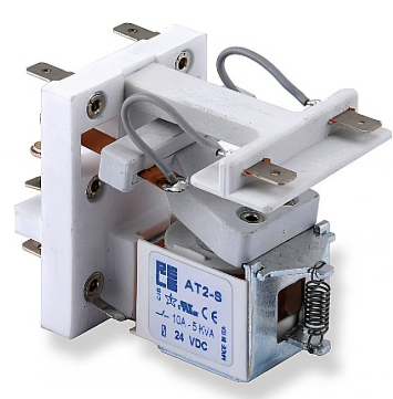
Figure 10: High-Voltage Relays
Time-delay relays operate after a set period, and thermal relays respond to temperature changes.
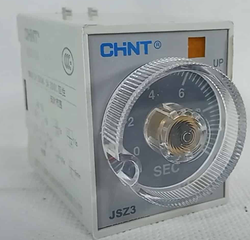
Figure 11: Time-Delay Relays
Differential relays are sensitive to minor current or voltage changes, distance relays monitor changes in distance, and automotive relays are designed specifically for vehicles.
Frequency relays respond to frequency changes, polarized relays operate under specific polarities, rotary relays work by rotating contacts, and sequential relays function in a pre-set order.
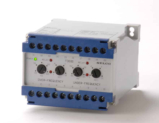
Figure 12: Frequency Relays
Moving-coil relays utilize the motion of a coil, Buchholz relays protect transformers, safety relays are used in safety systems, monitoring relays oversee circuit conditions, and ground fault relays detect grounding issues.
Figure 13: Moving-Coil Relays
Working Principles of Relays
The working principles of relays can be divided into two main categories: Electromechanical Relays (EMRs) and Solid-State Relays (SSRs). Both serve similar functions but operate through different mechanisms and are suited to distinct applications.
Electromechanical Relays (EMRs)
Electromechanical relays rely on electromagnetic forces to move mechanical parts and switch circuits. There are two modes: normally open (NO) and normally closed (NC).
In a normally open relay, the secondary circuit is open when the relay is not energized, preventing current flow. When current flows through the primary circuit, the electromagnet generates a magnetic field. This field pulls the armature, closing the contact in the secondary circuit and allowing current to flow.
In a normally closed relay, the secondary circuit is closed when the relay is not energized, allowing current to flow. When the primary circuit is energized, the magnetic field pushes the armature away, opening the contact and stopping current flow. This straightforward design makes EMRs ideal for applications needing physical isolation and clear mechanical feedback.
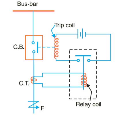
Figure 14: Electromechanical Relays Circuit Diagram
Solid-State Relays (SSRs)
However, solid-state relays use semiconductor materials for switching without mechanical parts.
The primary side of an SSR contains an LED. When current flows through, the LED emits photons. These photons pass through an optical coupler to the secondary side. The energy from the photons enables electrons in the P-type semiconductor to cross a barrier, creating current flow and closing the secondary circuit. When the LED is off, photon emission stops, preventing electrons from crossing the barrier, which opens the secondary circuit. SSRs offer advantages like no mechanical wear, fast response times, and the ability to handle high-frequency operations. They are perfect for industrial automation and computer control systems requiring quick and reliable switching.
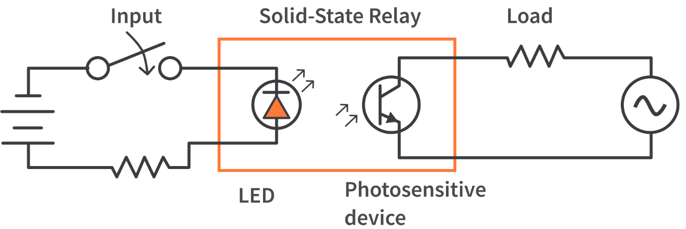
Figure 15: Solid-State Relays Circuit Diagram
Comparative Analysis
EMRs have an advantage due to their mechanical contacts that can withstand large current surges. SSRs are better suited due to their lack of moving parts, eliminating mechanical wear and reducing operational noise. However, SSRs may not perform as well in extreme temperatures or high-stress environments due to the sensitivity of their semiconductor components.
In industrial control systems, the high current capability of EMR is even more needed. In computer control and signal processing systems, the fast response and low noise of SSRs are more desirable. Choosing the right type of relay involves understanding these principles and matching them to the specific needs and environmental conditions of your application. This knowledge enables better circuit design and system optimization, enhancing overall performance and reliability.
Applications of Relays
Relays play an important role in modern electrical systems by using electrical signals to control circuit connections, providing protection, and enabling automation.
Audio Equipment
In audio amplifiers, relays switch input signals to ensure high-quality audio output. They also protect circuits from overloads or short circuits, preventing damage to the amplifier. When setting up an audio system, you might hear a distinct click as the relay engages, ensuring the right input is routed to the amplifier.
Modems
Relays in modems switch communication lines, allowing seamless transitions between different signals. This switching enhances data transmission reliability.
Automotive Systems
In cars, relays control starter solenoids, enabling the engine to start by managing the current flow. They are also used in controlling car lights, wipers, and power windows. For instance, when you turn the ignition key, you activate a relay that allows the starter motor to crank the engine.
Lighting Control Systems
Relays automate lighting by responding to timers or sensor signal, and turning lights on or off to save energy and increase convenience. In a home automation setup, installing a relay can mean your lights turn on automatically as you enter a room.
Telecommunications
In telecom systems, relays switch signals and protect lines, ensuring stable and secure communication. Working on a telecom system, you’ll appreciate the relay’s ability to handle high-frequency switching without wear and tear.
Industrial Process Controllers
Relays automate equipment control, ensuring continuous and efficient production processes. When programming an industrial controller, relays are used to start and stop machines, manage conveyor belts, and control robotic arms.
Traffic Control Systems
Relays manage traffic lights, ensuring orderly and safe traffic flow. As a technician, you might install relays in traffic lights, where they precisely control signal changes based on traffic patterns.
Motor Control
Relays control motor operations by switching current direction and flow, enabling motor start, stop, and reversal. In motor control circuits, relays allow precise control over motor functions, essential for machinery operation.
Power System Protection
Relays are vital in power systems, monitoring current and voltage to quickly respond to overcurrent or overvoltage conditions, protecting equipment from damage. For electricians, understanding relay settings can be beneficial in protecting electrical systems.
Computer Interfaces
Relays enable signal transmission and isolation between different devices, ensuring data accuracy and system stability. In computing, relays help in interfacing various peripherals, providing isolation to prevent damage from electrical faults.
Home Appliances
Relays control operations in household devices like washing machines, refrigerators, and air conditioners, enabling automated and energy-efficient functionality. When repairing appliances, you’ll often replace or troubleshoot relays to restore proper operation.
Broader Applications
Relays are also used in power distribution systems, emergency power switching, smart home systems, robotics, and medical devices. Their ability to precisely control electrical signals enhances system reliability and safety across diverse applications.
Through these varied uses, relays ensure equipment protection, efficient operation, and system reliability. Understanding their working principles and applications can significantly improve electrical system design and optimization, meeting the needs of complex and demanding environments.
How to Test a Relay?
Over time, a relay's performance can degrade, leading to failure. At this time, regular testing and maintenance are very necessary to ensure that the relay continues to operate smoothly and safely. Here are some detailed methods to effectively test a relay and ensure its reliability and safety.
Testing a relay with a multimeter is a common and straightforward method.
Start by removing the relay from the circuit to get accurate results. Use the multimeter to measure the resistance of the relay contacts. For a Normally Open (NO) contact, it should show high resistance when the relay is not energized and low resistance when energized. A Normally Closed (NC) contact, should show low resistance when not energized and high resistance when energized. If the resistance values are not as expected, the relay might be faulty and need further inspection or replacement.
Creating a simple test circuit is another effective way to test a relay.
Construct a basic circuit on a breadboard that includes a power supply, a switch, and the relay. Before powering the circuit, the NO contact should be open, and the NC contact should be closed. When the power is applied, the relay’s electromagnetic coil should activate, causing the NO contact to close and the NC contact to open. Check the change in states of the contacts to determine if the relay is working correctly.
A DC power supply provides a direct and effective method to test a relay.
Attach the relay coil pins to the DC power supply. Slowly increase the voltage and observe the relay contacts. The relay should switch at its rated voltage. If it fails to switch, the coil may be aged or damaged, or internal mechanical parts may be stuck.
Using your senses can also help in testing a relay.
When the relay is powered on and off, you should hear a distinct "click" sound indicating the mechanical parts are moving. Use an LED or other indicators connected to the relay contacts. When the relay switches, the LED should turn on or off accordingly.
Please pay attention to safety during operation, and ensure safety during testing, especially when using high-speed electronics. Wear appropriate protective gear and use insulated tools to avoid electrical shocks.
Conclusion
The intricate design and versatile applications of relays underscore their indispensable role in modern technology. Whether in industrial automation, automotive systems, or home appliances, relays provide precise control over electrical circuits, enhancing both efficiency and safety. Through detailed construction involving components like electromagnets and mechanical contacts, relays can manage high currents and protect sensitive equipment from damage. The distinction between Electromechanical Relays (EMRs) and Solid-State Relays (SSRs) further highlights the adaptability of relays to different operational demands, with EMRs offering robust performance in high-current applications and SSRs excelling in environments requiring rapid and silent switching. Regular testing and maintenance using methods such as resistance check with a multimeter or building a test circuit will help ensure long-term reliable operation. By comprehensively understanding and leveraging the capabilities of relays, engineers and technicians can significantly enhance the design and performance of electrical systems, meeting the ever-evolving needs of various applications.
Frequently Asked Questions [FAQ]
1. How do relays work in a circuit?
Relays work in a circuit by using an electromagnet to mechanically operate a switch. When an electric current passes through the relay's coil, it generates a magnetic field that attracts a movable armature, causing it to change the state of the switch contacts (open or close). This allows a low-power signal to control a higher-power circuit.
2. Why do you need a relay in a circuit?
Control high-power devices: Relays enable a low-power control signal to switch high-power loads.
Isolate circuits: They provide electrical isolation between the control and load circuits, enhancing safety.
Perform logic functions: Relays can be used to create complex control systems that require multiple inputs and outputs.
3. What are the three basic functions of a relay?
Switching: Relays switch electrical circuits on and off.
Isolation: They isolate different parts of a circuit to protect sensitive components from high currents or voltages.
Control: Relays allow one circuit to control another, enabling automation and complex control logic.
4. How do you test a relay?
Using a multimeter: Measure the resistance of the relay's coil and contacts. The coil should have a specific resistance value, while the Normally Open (NO) contacts should show high resistance when de-energized and low when energized. Normally Closed (NC) contacts should show the opposite.
Creating a test circuit: Connect the relay to a power source and a load. When power is applied to the relay's coil, the contacts should switch states (NO should close, NC should open).
Listening for a click: When the relay is activated, you should hear a clicking sound indicating the mechanical movement of the contacts.
5. What can cause a relay to fail?
Mechanical wear: Repeated operation can wear out the mechanical parts.
Electrical arcing: High currents can cause arcing across the contacts, leading to pitting and damage.
Coil failure: Excessive voltage or prolonged use can damage the relay coil.
Contamination: Dust, dirt, or moisture can interfere with the mechanical movement and electrical contacts.
Thermal stress: High temperatures can degrade the materials and cause malfunction.
About us
ALLELCO LIMITED
Read more
Quick inquiry
Please send an inquiry, we will respond immediately.
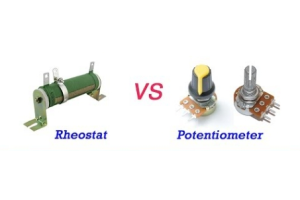
Comparative Guide to Analyzing rheostat and Potentiometers
on May 17th
Comparing Carbon Film Resistors and Metal Film Resistors - Advantages and Disadvantages, Performance, Structure
on May 15th
Popular Posts
-

What is GND in the circuit?
on January 1th 2944
-

RJ-45 Connector Guide: RJ-45 Connector Color Codes, Wiring Schemes, R-J45 Applications, RJ-45 Datasheets
on January 1th 2501
-

Fiber Connector Types: SC Vs LC And LC Vs MTP
on January 1th 2089
-

Understanding Power Supply Voltages in Electronics VCC, VDD, VEE, VSS, and GND
on November 9th 1895
-

Comparison Between DB9 and RS232
on January 1th 1765
-

What Is An LR44 Battery?
Electricity, that ubiquitous force, quietly permeates every aspect of our daily lives, from trivial gadgets to life-threatening medical equipment, it plays a silent role. However, truly grasping this energy, especially how to store and efficiently output it, is no easy task. It is against this background that this article will focus on a type of coin cell battery that may seem insignificant on the...on January 1th 1714
-

Understanding the Fundamentals:Inductance Resistance, andCapacitance
In the intricate dance of electrical engineering, a trio of fundamental elements takes center stage: inductance, resistance, and capacitance. Each bears unique traits that dictate the dynamic rhythms of electronic circuits. Here, we embark on a journey to decipher the complexities of these components, to uncover their distinct roles and practical uses within the vast electrical orchestra. Inductan...on January 1th 1657
-

CR2430 Battery Comprehensive Guide: Specifications, Applications and Comparison to CR2032 Batteries
What is CR2430 battery ?Benefits of CR2430 BatteriesNormCR2430 Battery ApplicationsCR2430 EquivalentCR2430 VS CR2032Battery CR2430 SizeWhat to look for when buying the CR2430 and equivalentsData Sheet PDFFrequently Asked Questions Batteries are the heart of small electronic devices. Among the many types available, coin cells play a crucial role, commonly found in calculators, remote controls, and ...on January 1th 1556
-

What Is RF and Why Do We Use It?
Radio Frequency (RF) technology is a key part of modern wireless communication, enabling data transmission over long distances without physical connections. This article delves into the basics of RF, explaining how electromagnetic radiation (EMR) makes RF communication possible. We will explore the principles of EMR, the creation and control of RF signals, and their wide-ranging uses. The article ...on January 1th 1543
-

CR2450 vs CR2032: Can The Battery Be Used Instead?
Lithium manganese batteries do have some similarities with other lithium batteries. High energy density and long service life are the characteristics they have in common. This kind of battery has won the trust and favor of many consumers because of its unique safety. Expensive tech gadgets? Small appliances in our homes? Look around and you'll see them everywhere. Among these many lithium-manganes...on January 1th 1513
HOT Part Number
-

MIC5209-3.3YS
Microchip Technology
IC REG LIN 3.3V 500MA SOT223-3
JAN1N2973B
Microchip Technology
ZENER DIODE
C1608CH1H222J080AA
TDK Corporation
CAP CER 2200PF 50V CH 0603
AFE4491ZRCT
Texas Instruments
IC ANALOG FRONT END BGA
CY14U256LA-BA35XI
Infineon Technologies
IC NVSRAM 256KBIT PAR 48FBGA
06031C182KAT4A
KYOCERA AVX
CAP CER 1800PF 100V X7R 0603
NCP2809ADMR2G
onsemi
IC AMP AB STEREO 135MW 10MICRO
AD767JNZ
Analog Devices Inc.
IC DAC 12BIT V-OUT 24DIP
NCP177AMX180TCG
onsemi
IC REG LINEAR 1.8V 500MA 4XDFN
BYW4200B-TR
STMicroelectronics
DIODE GEN PURP 200V 4A DPAK
CC1206KRX7R9BB124
YAGEO
CAP CER 0.12UF 50V X7R 1206
TVP5150AM1IPBS
Texas Instruments
IC VIDEO DECODER 9BIT 32TQFP
CAV24C256WE-GT3
onsemi
IC EEPROM 256KBIT I2C 1MHZ 8SOIC
SN74ALS576BN
Texas Instruments
IC FF D-TYPE SNGL 8BIT 20DIP
1210SC821KAT1A
KYOCERA AVX
CAP CER 820PF 1.5KV X7R 1210
CL21B224KAF4PNE
Samsung Electro-Mechanics
CAP CER 0.22UF 25V X7R 0805
NTMFS4709NT1G
onsemi
NFET S08FL 30V 94A .003R
DDA113TU-7-F
Diodes Incorporated
TRANS 2PNP PREBIAS 0.2W SOT363 -

ICL7664AITV
Analog Devices Inc./Maxim Integrated
IC REG LINEAR PROGRAMMABLE VOLT
GRM0225C1E7R8BA03L
Murata Electronics
CAP CER 7.8PF 25V C0G/NP0 01005
FDS4435BZ
onsemi
MOSFET P-CH 30V 8.8A 8SOIC
NCV33161DMR2G
onsemi
IC SUPERVISOR 2 CHANNEL MICRO8
74LCXH162244MTD
Fairchild Semiconductor
IC BUFF NON-INVERT 3.6V 48TSSOP
CS51414EDR8G
onsemi
IC REG BUCK ADJ 1.5A 8SOIC
GRM1555C1H6R2BZ01J
Murata Electronics
CAP CER 6.2PF 50V C0G/NP0 0402
TL052AID
Texas Instruments
IC OPAMP JFET 2 CIRCUIT 8SOIC
LC72151VS-TRM-E
Sanyo
PLL FREQUENCY SYNTHESIZER FOR EL
SA12CA-E3/73
Vishay General Semiconductor - Diodes Division
TVS DIODE 12VWM 19.9VC DO204AC
IXTH110N25T
IXYS
MOSFET N-CH 250V 110A TO247
MIC4576WU-TR
Microchip Technology
IC REG BUCK ADJ 3A TO263-5
MAX667CPA+
Analog Devices Inc./Maxim Integrated
IC REG LIN POS ADJ 250MA 8DIP
IS43QR16512A-083TBLI-TR
ISSI, Integrated Silicon Solution Inc
8G, 1.2V, DDR4, 512Mx16, 2400MT/
CD74ACT574M
Texas Instruments
IC FF D-TYPE SNGL 8BIT 20SOIC
LTC2903CS6-A1#TRPBF
Analog Devices Inc.
IC SUPERVISOR 4 CHANNEL TSOT23-6
IS61WV20488BLL-10TLI
ISSI, Integrated Silicon Solution Inc
IC SRAM 16MBIT PAR 44TSOP II
MT29E6T08ETHBBM5-3:B
Micron Technology Inc.
IC FLASH 6TBIT PARALLEL 333MHZ -

87008AGILF
Renesas Electronics America Inc
IC CLOCK GENERATOR 24TSSOP
STD888T4
STMicroelectronics
TRANS PNP 30V 5A DPAK
ST715M33R
STMicroelectronics
IC REG LINEAR 3.3V 85MA SOT23-5
VLS252012ET-1R0N
TDK Corporation
FIXED IND 1UH 1.7A 87 MOHM SMD
MC74HC373AFEL
onsemi
BUS DRIVER, HC/UH SERIES
04023C822JAT2A
KYOCERA AVX
CAP CER 8200PF 25V X7R 0402
MC10135P
onsemi
FLIP FLOP JK-MASTER-SLAVE TYPE
MBR10100CTP
SMC Diode Solutions
DIODE ARRAY SCHOTTKY 100V TO220
18121C474KAT2A
KYOCERA AVX
CAP CER 0.47UF 100V X7R 1812
LTC203CS#TRPBF
Analog Devices Inc.
IC SW SPST-NO/NCX4 125OHM 16SO
IPS1-120-01-S-D
Samtec Inc.
CONN RCPT 40POS 0.1 GOLD PCB
MC1496BDR2G
onsemi
IC MODULATOR/DEMODULATOR 14-SOIC
COP8SDR9HVA8
Texas Instruments
IC MCU 8BIT 32KB FLASH 44PLCC
PTZTE2518A
Rohm Semiconductor
DIODE ZENER 18V 1W PMDS
MMBTH10LT1G
onsemi
RF TRANS NPN 25V 650MHZ SOT23-3
MC100LVEP210FARG
onsemi
IC CLK/DRVR DUAL DIF 1:5 32-LQFP
CLF10040T-221M
TDK Corporation
FIXED IND 220UH 700MA 624MOHM SM
MAX218CWP+
Analog Devices Inc./Maxim Integrated
IC TRANSCEIVER FULL 2/2 20SOIC