Inductor, Choke Coil & Transformer Circuit Symbols
In electrical engineering, circuit symbols help make communication clear and simple by providing an easy way to represent different parts of an electrical system. Inductors and transformers are important because they control and change electrical energy. Symbols for inductors and transformers are more than just visual aids, they are used for the design, analysis, and troubleshooting of electrical circuits. These standardized symbols allow engineers to quickly grasp the functional elements of a circuit, facilitating both clear communication and efficient problem-solving.This article focuses on the symbols used for inductors and transformers, includes diagrams and explains the functions and different types of these components. It looks at various kinds of inductors, like simple air-core and more complex saturable core ones, as well as different transformer designs, such as iron-core and ferrite-core types.
Catalog
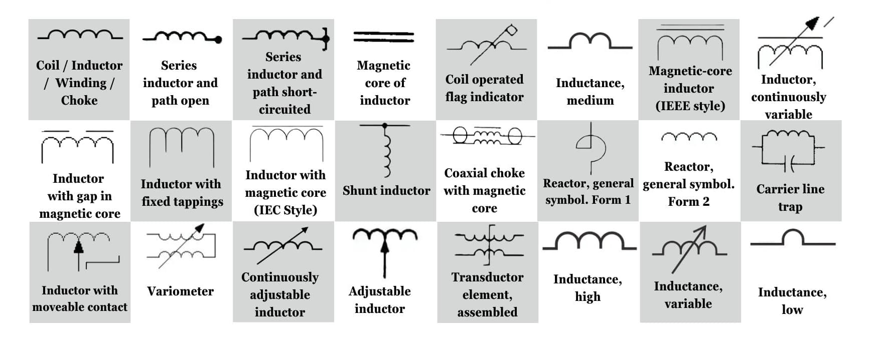
Figure 1: Circuit Symbols Examples
Meaning of the Inductor's Symbol
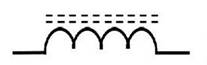
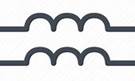
Inductors are shown with curved or zigzag lines, represent a coiled wire. When electricity flows through the coil, it creates a magnetic field. This simple symbol lets engineers quickly spot parts of a circuit that store energy in a magnetic field or help filter signals. The straightforward design makes it easier to understand and work with circuits involving energy storage or current control.
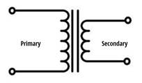
Meaning of the Transformer's Symbol
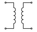
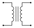
Transformers are drawn using two inductor symbols next to each other, often with parallel lines between them to represent the core around which the coils are wound. This symbol shows the transformer’s main job: changing voltage levels using electromagnetic induction. The core is made from a magnetic material like iron, helps strengthen the magnetic link between the coils. The transformer symbol ma kes it clear that the device is used to adjust voltage or keep different parts of the circuit separate, which is important in power systems.
Inductor Schematic Symbols
|
Circuit Symbol |
Symbol Identification |
Description of Symbol |
|
|
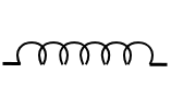
Generic Fixed Inductor |
This symbol stands for a basic fixed
inductor, also called a coil or choke. It has a set inductance value and
works by storing energy in a magnetic field. Fixed inductors help control the
flow of current, filter signals, and reduce noise by using the energy stored
in their magnetic field. |
|
|
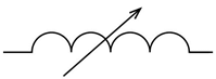
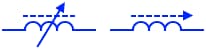
Variable Inductor |
A variable inductor is a device that can
change its inductance to suit different circuit needs. It's mainly used in
radio frequency circuits to adjust the resonance frequency for better signal
quality. Changing the inductance often involves moving a core inside the coil
that alters the magnetic field. |
|
|
Inductor with Polarity |
Some inductors have a dot on one terminal
to show the preferred direction for current flow. This marking is important
when using two inductors together to ensure proper magnetic coupling. If the
dots are aligned, the inductors work together more effectively. |
|
|
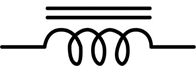
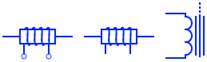
Iron Core Inductor |
An iron core inductor has a core made of
iron, a material that can easily carry magnetic energy. This makes the
inductor better at storing magnetic energy and increases its inductance. |
|
|
Ferrite Core Inductor |
A ferrite core inductor has a core made
of ferrite because it has useful qualities. Ferrite can hold more magnetic
energy due to its high magnetic permeability, and its low electrical
conductivity helps cut down energy losses from eddy currents. |
|
|
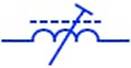
Variable Ferrite Core Inductor |
A variable ferrite core inductor lets you
adjust its inductance by moving the ferrite core in or out of the coil.
Turning the core in increases the inductance, while pulling it out decreases
it. This happens because the ferrite material affects the magnetic field
inside the coil: more core inside means stronger inductance, and less core
means weaker inductance. |
|
|
Preset Ferrite Core Inductor |
A preset ferrite core inductor is a
component with its inductance adjusted once, either during manufacturing or
when first setting up the circuit. After this adjustment, the inductance
remains fixed, ensuring stable and reliable performance during regular use. |
|
|
Shielded Inductor |
A shielded inductor has a core that traps
its magnetic field inside, preventing it from leaking out and affecting
nearby parts. The shield also blocks outside electromagnetic noise, helping
the inductor perform better in complex electronic systems. |
|
|
Electromagnet Solenoid |
A solenoid is a tube-shaped coil of wire
that produces a magnetic field when electricity flows through it. The
strength of this field depends on how many times the wire is wrapped, the
electric current, and the material inside the coil. |
|
|
Electromagnetic Deflection Coil |
A deflection coil is important for how
cathode ray tubes (CRTs) work. It makes a magnetic field that moves the
electron beam. |
|
|
Bifilar Inductor |
A bifilar inductor is made by winding two
wires side by side, with each loop of one wire matching the other. If the
wires are wound in opposite directions, their currents flow in reverse,
cancelling out their magnetic fields and reducing the inductance. |
|
|
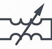
Variometer |
A variometer is a device that adjusts
inductance by moving two connected coils. These coils are arranged in a
series and can be rotated or slid relative to each other. The inductance is
highest when both coils face the same way and lowest when they face opposite
directions. |
|
|
Saturable Core Inductor |
A saturable core inductor is made to fill
its core with magnetism. When this happens, it becomes less effective at
blocking AC current, allowing more current to flow through. |
|
|
Electric Motor Inductor |
An electric motor's inductor, turns
electrical energy into mechanical power through electromagnetic induction.
The coil's design and materials impact the motor's efficiency. The coil
generates a magnetic field that interacts with the rotor to make the motor
run. |
|
|
Analog Delay Line |
An analog delay line slows down an analog
signal to change its timing. It works by making the signal travel more slowly
through materials like coiled wires, similar to how a digital buffer delays
signals. |
|
|
Tapped Inductor |
A tapped inductor is a coil with
connection points, called taps, along the wire. These taps allow you to
adjust its electrical properties, like impedance, without changing the
design. |


Transformer Schematic Symbols
|
Circuit Symbol |
Symbol Identification |
Description of Symbol |
 |
Air-core Transformer |
An air-core voltage transformer for radio
frequencies (RF) has two coils linked by magnetism. These coils are wrapped
around a non-magnetic core. Since it doesn't use a magnetic core, the
transformer avoids problems like energy loss and saturation that occur at
high frequencies. |
 |
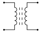
Iron-core Transformer |
An iron-core transformer is a type of
single-phase voltage transformer that uses a core made of thin layers of iron
to work better. It has two coils of wire, called windings, that are wrapped
around the core. The iron core helps direct the magnetic field created by the
windings, making sure electrical energy moves efficiently from one winding to
the other. |
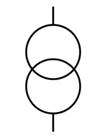 |
Power Transformer |
A single-phase power transformer, often
shown as two linked circles in diagrams. Its main function is to increase or
decrease voltage, based on the needs of the power grid. |
 |
Ferrite-core Transformer |
A ferrite-core transformer is a type of
transformer with two coils wrapped around a core made of ferrite, a
compressed material. The core’s special design reduces energy loss and noise,
like the humming sound transformers often make. |
|
|
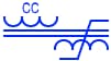
Step-down Transformer |
A single-phase step-down isolation
transformer lowers the voltage from the primary winding to the secondary
winding. This happens because the primary winding has more wire turns than
the secondary winding. The voltage drop depends on the ratio of wire turns. |
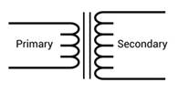 |
Step-up Transformer |
A single-phase step-up isolation
transformer increases voltage from the primary side to a higher level on the
secondary side. The voltage change depends on the "turn ratio," or
how these two sets of windings are connected. |
Conclusion
This article gives a clear explanation of how the symbols for inductors and transformers are connected to how they work in real circuits. By explaining the different kinds of inductors and transformers, it helps readers better understand diagrams and the basics of how electromagnetic systems work in electronics. This knowledge is important for improving how devices perform and for solving problems in real-life situations.
Frequently Asked Questions [FAQ]
1. What is an inductor used for?
An inductor can store energy in a magnetic field when electricity passes through it. This feature makes inductors useful for things like filtering signals, controlling voltage, and tuning circuits. For example, in power supplies, inductors help even out changes in current and keep the voltage steady. In radio circuits, they are used to pick certain frequencies, helps in tuning to different stations.
2. What is the basic unit of inductor?
The basic unit of measurement for an inductor is the henry (H). An inductor has one henry when a current change of one ampere per second induces a voltage of one volt across the inductor.
3. How is inductor represented?
An inductor is represented by a series of curved lines or loops, symbolizing the coil of wire that constitutes the inductor. This symbolic representation helps in identifying the component in circuit diagrams and distinguishing it from other elements like resistors or capacitors.
4. What are the 3 types of transformers?
Transformers can be classified into three main types based on their purpose and construction:
Step-up Transformer: Increases voltage from primary to secondary coil, useful in applications where a higher voltage output is needed from a lower voltage input.
Step-down Transformer: Decreases voltage from primary to secondary coil, used in household appliances to convert high mains voltage to lower, safer levels.
Isolation Transformer: Provides electrical isolation between the primary and secondary coils without changing the voltage level, enhancing safety in sensitive electronics.
5. What are the uses of transformers?
Transformers are used in electrical systems due to their ability to change voltage levels, making them suitable for a variety of purposes. Their main functions include voltage control, helps maintain steady voltage in power systems to prevent damage to electrical devices. They adjust impedance, balancing it between circuits to ensure efficient power transfer. Lastly, transformers provide isolation by keeping circuits separate, reduces interference and enhances safety.
6. What is the basic principle of transformer?
The basic principle of a transformer is electromagnetic induction. In simple terms, a transformer works by using two coils of wire (primary and secondary coils) wound around a common core. When an alternating current flows through the primary coil, it creates a varying magnetic field. This magnetic field induces a voltage in the secondary coil. The ratio of the voltages in the primary and secondary coils is directly proportional to the ratio of the number of turns of wire in the respective coils, allowing the transformer to increase or decrease voltage as needed.
About us
ALLELCO LIMITED
Read more
Quick inquiry
Please send an inquiry, we will respond immediately.
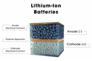
Discovering the Pros and Cons of Lithium-Ion Batteries
on August 22th
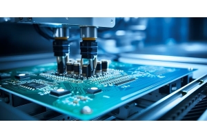
Surface Mount Technology (SMT)
on August 21th
Popular Posts
-

What is GND in the circuit?
on January 1th 2893
-

RJ-45 Connector Guide: RJ-45 Connector Color Codes, Wiring Schemes, R-J45 Applications, RJ-45 Datasheets
on January 1th 2462
-

Fiber Connector Types: SC Vs LC And LC Vs MTP
on January 1th 2056
-

Understanding Power Supply Voltages in Electronics VCC, VDD, VEE, VSS, and GND
on November 7th 1828
-

Comparison Between DB9 and RS232
on January 1th 1746
-

What Is An LR44 Battery?
Electricity, that ubiquitous force, quietly permeates every aspect of our daily lives, from trivial gadgets to life-threatening medical equipment, it plays a silent role. However, truly grasping this energy, especially how to store and efficiently output it, is no easy task. It is against this background that this article will focus on a type of coin cell battery that may seem insignificant on the...on January 1th 1699
-

Understanding the Fundamentals:Inductance Resistance, andCapacitance
In the intricate dance of electrical engineering, a trio of fundamental elements takes center stage: inductance, resistance, and capacitance. Each bears unique traits that dictate the dynamic rhythms of electronic circuits. Here, we embark on a journey to decipher the complexities of these components, to uncover their distinct roles and practical uses within the vast electrical orchestra. Inductan...on January 1th 1641
-

CR2430 Battery Comprehensive Guide: Specifications, Applications and Comparison to CR2032 Batteries
What is CR2430 battery ?Benefits of CR2430 BatteriesNormCR2430 Battery ApplicationsCR2430 EquivalentCR2430 VS CR2032Battery CR2430 SizeWhat to look for when buying the CR2430 and equivalentsData Sheet PDFFrequently Asked Questions Batteries are the heart of small electronic devices. Among the many types available, coin cells play a crucial role, commonly found in calculators, remote controls, and ...on January 1th 1515
-

What Is RF and Why Do We Use It?
Radio Frequency (RF) technology is a key part of modern wireless communication, enabling data transmission over long distances without physical connections. This article delves into the basics of RF, explaining how electromagnetic radiation (EMR) makes RF communication possible. We will explore the principles of EMR, the creation and control of RF signals, and their wide-ranging uses. The article ...on January 1th 1504
-

CR2450 vs CR2032: Can The Battery Be Used Instead?
Lithium manganese batteries do have some similarities with other lithium batteries. High energy density and long service life are the characteristics they have in common. This kind of battery has won the trust and favor of many consumers because of its unique safety. Expensive tech gadgets? Small appliances in our homes? Look around and you'll see them everywhere. Among these many lithium-manganes...on January 1th 1485
HOT Part Number
-
MAX3095EPE
Analog Devices Inc./Maxim Integrated
IC RECEIVER 0/4 16DIP
SMBJ8V0CA
Fairchild Semiconductor
TVS DIODE 8VWM 13.6VC DO214AA
EPM570F256C3N
Intel
IC CPLD 440MC 5.4NS 256FBGA
PE-65968NL
Pulse Electronics
TRANSFORMER TELECOM SINGLE T3/E4
12105C225K4T2A
KYOCERA AVX
CAP CER 2.2UF 50V X7R 1210
0603ZA100KAT2A
KYOCERA AVX
CAP CER 10PF 10V NP0 0603
BD9763FVM-TR
Rohm Semiconductor
IC REG CTRLR BOOST 8MSOP
TLC2252ID
Texas Instruments
IC OPAMP GP 2 CIRCUIT 8SOIC
RP170N301D-TR-FE
Nisshinbo Micro Devices Inc.
IC REG LINEAR 3V 300MA SOT23-5
08051U4R3CAT2A
KYOCERA AVX
CAP CER 4.3PF 100V NP0 0805
ATA6663-FAQW-1
Microchip Technology
IC TRANSCEIVER HALF 1/1 8DFN
XCV600-4BG432I
AMD
IC FPGA 316 I/O 432MBGA
12101U220JAT2A
KYOCERA AVX
CAP CER 22PF 100V NP0 1210
C0402C0G1C750J
TDK Corporation
CAP CER 75PF 16V C0G 01005
MAX20006AFOA/VY+T
Analog Devices Inc./Maxim Integrated
36V, 220KHZ TO 2.2MHZ, 4A/6A/8A
BUZ73A H
Infineon Technologies
MOSFET N-CH 200V 5.5A TO220-3
0603ZC562KAT2A
KYOCERA AVX
CAP CER 5600PF 10V X7R 0603
PCM2705DBRG4
Texas Instruments
IC AUDIO 16BIT 48K 28SSOP -

TC35678FSG-002
Toshiba Semiconductor and Storage
IC RF TXRX+MCU BLUETOOTH 60VFQFN
MLG0603P36NHT000
TDK Corporation
FIXED IND 36NH 120MA 2.4 OHM SMD
SN74LVT244BDWG4
Texas Instruments
IC BUF NON-INVERT 3.6V 20SOIC
AT45DB041D-MU-2.5
Adesto Technologies
IC FLASH 4MBIT SPI 50MHZ 8VDFN
STGB10NB40LZT4
STMicroelectronics
IGBT 440V 20A 150W D2PAK
XC95288XL-6TQG144C
AMD
IC CPLD 288MC 6NS 144TQFP
LT8580EMS8E#PBF
Analog Devices Inc.
IC REG MULT CONFG ADJ 1.2A 8MSOP
ICM7212AIPL
Analog Devices Inc./Maxim Integrated
IC DECODR/DVR LED 4DIGIT 40-DIP
ADG429TQ
Analog Devices Inc.
IC SWITCH SP4TX2 100OHM 18CERDIP
HEF4021BT,653
Nexperia USA Inc.
IC STATIC SHIFT REG 8BIT 16SOIC
SC4808AIMSTRT
Semtech Corporation
IC OFFLINE SW MULT TOP 10MSOP
EP2S90F1020C5
Intel
IC FPGA 758 I/O 1020FBGA
XC7A50T-L2CSG324E
AMD
IC FPGA 210 I/O 324CSBGA
NVF3055L108T1G
onsemi
MOSFET N-CH 60V 3A SOT223
SMP1320-077LF
Skyworks Solutions Inc.
RF DIODE PIN 50V 250MW SC70-3
AD5259BRMZ100-R7
Analog Devices Inc.
IC DGT POT 100KOHM 256TAP 10MSOP
LT3030EFE#PBF
Analog Devices Inc.
IC REG LINEAR POS ADJ 20TSSOP
2SC4081U3T106R
Rohm Semiconductor
TRANS NPN 50V 0.15A UMT3 -

C200H-DA001
Omron Automation and Safety
OUTPUT MODULE 2 ANALOG
LV8130V-MPB-H
onsemi
DIRECT PWM DRIVE,QUIET PREDRIVER
MCDP6200C1
Kinetic Technologies
USB TYPE-C SWITCHING RETIMER 46-
C8051F506-IMR
Silicon Labs
IC MCU 8BIT 32KB FLASH 32QFN
SSA500AA80
SanRex Corporation
THYRISTOR MODULE 800V 500A
MC9S08LC36LH
NXP USA Inc.
IC MCU 8BIT 36KB FLASH 64LQFP
2SD1626-TD-E
onsemi
TRANS NPN 50V 1.5A PCP
AD5065ARUZ
Analog Devices Inc.
IC DAC 16BIT V-OUT 14TSSOP
B39731B8811P810
Qualcomm (RF front-end (RFFE) filters)
FILTER SAW RFFE 1109 SMD
ADP2108AUJZ-1.1-R7
Analog Devices Inc.
IC REG BUCK 1.1V 600MA TSOT23-5
BKP1608HS101-T
Taiyo Yuden
FERRITE BEAD 100 OHM 0603 1LN
MAX7432EUD-T
Analog Devices Inc./Maxim Integrated
SD VIDEO RECONSTRUCTION FILTER
FKC08-24D15
P-DUKE Technology, Inc.
DC DC CONVERTER +/-15V 8W
AD5235BRUZ250
Analog Devices Inc.
IC DGTL POT 250KOHM 16TSSOP
01020071Z
Littelfuse Inc.
FUSE CLIP CARTRIDGE 250V 15A PCB
08053A100KAT2A
KYOCERA AVX
CAP CER 10PF 25V NP0 0805
08055C121KAT2A
AVX Corporation
CAP CER 120PF 50V X7R 0805
ADG5434BRUZ-REEL7
Analog Devices Inc.
IC SWITCH SPDT X 4 14OHM 20TSSOP