Surface Mount Technology (SMT)
Surface Mount Technology (SMT) has changed the way electronic devices are made. As electronic gadgets keep getting smaller, faster, and more powerful, it’s become more and more important to have manufacturing methods that are both efficient and reliable. SMT meets this need by allowing electronic components to be placed directly onto the surface of printed circuit boards (PCBs), instead of the older method where components had to be inserted through holes in the board. This new way of doing things not only speeds up the manufacturing process but also makes it possible to create smaller, more complex, and more durable electronic devices.Catalog
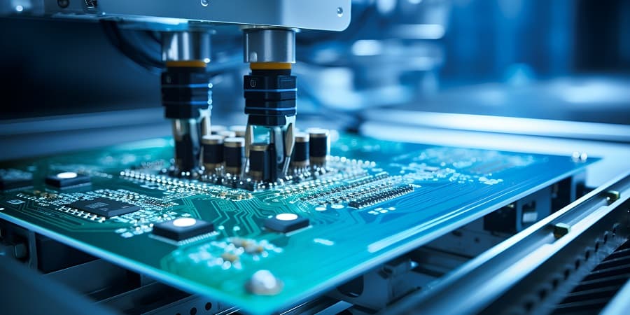
Figure 1: Surface Mount Technology (SMT)
What Is Surface Mount Technology (SMT)?
Surface Mount Technology (SMT) is a way of building electronic devices where components are placed directly onto the surface of a Printed Circuit Board (PCB). Unlike older methods, where parts had wires that went through holes in the board, SMT places the components directly on the PCB without needing those holes.
One big advantage of SMT is that it works well with machines that can assemble these components automatically. Since the parts are placed directly onto the PCB, machines can quickly and accurately put many components in place in a short time. This automation makes the process faster and less expensive, making SMT the preferred method for producing large quantities of electronic products.
Another benefit of SMT is that it allows for smaller and more complex electronic devices. Without the need for holes in the board, components can be placed closer together and on both sides of the PCB, which saves space. This is especially useful in today’s electronics, where gadgets are getting smaller and more powerful.
The technical side of SMT includes using a paste that holds the components on the PCB temporarily. This paste contains tiny solder balls that melt when the board is heated in a special oven, creating permanent connections between the components and the PCB.
The Evolution of Surface Mount Technology
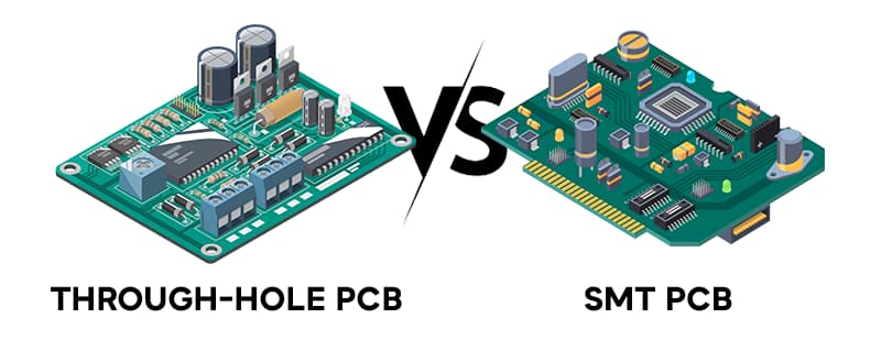
Figure 2: Through-Hole PCB vs. SMT PCB
Surface Mount Technology (SMT) came into the spotlight during the 1970s and 1980s when there was a growing need for smaller and more advanced electronic devices. At that time, traditional methods for assembling electronic components—where parts with metal legs were inserted into holes on a Printed Circuit Board (PCB)—started to become less practical. This older method involved larger parts and a lengthy process of placing these parts through drilled holes, which made it harder to keep up with the demand for smaller and more complex devices.
SMT introduced a new approach by allowing electronic parts to be placed directly on the surface of the PCB without needing to drill holes. This change not only made the components and the boards themselves smaller but also sped up the manufacturing process. By skipping the step of inserting leads into holes, SMT made it possible to produce electronic devices more quickly, which was very helpful as the demand for these devices increased. The smaller size of the components also allowed more parts to fit on the board, making it possible to add more functions into smaller devices, something that has become very common in today's electronics.
SMT also offered better durability compared to the older methods. Parts mounted on the surface of the PCB are less likely to be damaged by movement or vibration, leading to longer-lasting electronic devices. This increased durability, along with the lower costs of materials and more efficient production, made SMT the best choice for mass-producing electronic devices.
Key Components of Surface-Mount Technology (SMT)
Surface-Mount Devices (SMDs) are the basic elements used in Surface-Mount Technology (SMT). Unlike traditional components with leads that go through holes in a printed circuit board (PCB), SMDs are designed to be placed directly onto the PCB's surface. This design allows for more compact and efficient electronic circuits. SMDs come in three main types: Passive Components, Transistors and Diodes, and Integrated Circuits (ICs).
Passive Components
This group includes resistors, capacitors, and inductors. These components help control electrical signals in a circuit. SMD resistors and capacitors are especially common and are available in standard sizes like 1812, 1206, 0805, 0603, 0402, and 0201. The numbers show the component's size in hundredths of an inch, with the first two digits indicating the length and the last two the width. The move to smaller sizes in SMDs has made it possible to create more compact circuit designs, allowing for the development of modern, smaller electronic devices.
These measurements help decide which components are right for different electronic circuits, especially when designing for smaller and more efficient modern devices.
|
SMD Size |
Length (inches) |
Width (inches) |
Length (mm) |
Width (mm) |
|
1812 |
0.180 |
0.120 |
4.50 |
3.20 |
|
1206 |
0.125 |
0.060 |
3.20 |
1.60 |
|
0805 |
0.080 |
0.050 |
2.00 |
1.25 |
|
0603 |
0.063 |
0.031 |
1.60 |
0.80 |
|
0402 |
0.040 |
0.020 |
1.00 |
0.50 |
|
0201 |
0.024 |
0.012 |
0.60 |
0.30 |
Transistors and Diodes
Transistors and diodes in SMT are usually packaged in small plastic cases. These cases have leads (metal legs) that are bent to touch the PCB. These components generally have three leads, which are arranged to make it easy to place them correctly on the board. Their small size and surface-mount design help save space on the PCB, allowing for more components to fit on a single board, which increases the circuit’s functionality.
Integrated Circuits (ICs)
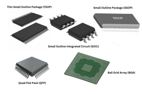
Figure 3: Different Types of SMT IC Packages
ICs in SMT come in different types of packages, which are chosen based on how complex the circuit is and how many connections are needed. Common IC packages include the Small Outline Integrated Circuit (SOIC), Thin Small Outline Package (TSOP), and Small Outline Package (SSOP). These packages have leads that extend from the sides, designed to be easily mounted on the PCB surface. For more complex ICs that need more connections and higher performance, packages like Quad Flat Pack (QFP) and Ball Grid Array (BGA) are used. The BGA package, in particular, is known for providing a large number of connections in a small space, using an array of tiny solder balls on the underside of the package to connect to the PCB.
SMT Manufacturing Process
The SMT manufacturing process includes several important steps to ensure that the SMDs are correctly placed and soldered onto the PCB. This process is highly automated, which helps increase efficiency and consistency in producing large quantities of electronic circuits.
Solder Paste Application
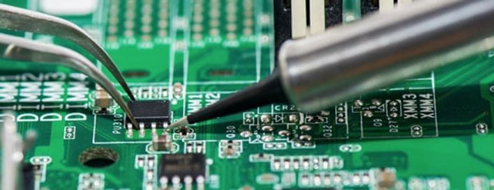
Figure 4: Application of Solder Paste in SMT Process
The process starts with the application of solder paste, a thick mixture of tiny solder particles and flux (a chemical used to clean and prepare surfaces for soldering). The solder paste is applied to the PCB's pads, which are the spots where the SMDs will be placed. A stencil is used to apply the paste only on these pads, making sure that solder is present only where it's needed. This step is very important because the amount and placement of solder paste directly affect the quality of the solder joints and the overall reliability of the circuit.
Component Placement
After the solder paste is applied, automated machines, known as pick-and-place machines, position the SMDs onto the solder-paste-coated pads. These machines are very accurate and can place components at high speeds, which is necessary for making complex electronic circuits. The correct orientation and placement of each component are ensured by advanced vision systems that guide the machines.
Reflow Soldering
Once all the components are in place on the PCB, the assembly is moved into a reflow oven. During reflow soldering, the PCB is heated in a controlled way, causing the solder paste to melt. As the PCB cools down, the solder hardens, forming strong mechanical and electrical connections between the components and the PCB. The temperature in the reflow oven is carefully controlled to avoid damaging the components and to make sure the soldering process is uniform across the entire board.
Inspection and Testing
After soldering, the assembled PCB goes through thorough inspection and testing to make sure all components are placed correctly and there are no defects in the solder joints. This inspection process usually involves Automated Optical Inspection (AOI), where cameras and software are used to detect misaligned or missing components or issues with solder. In addition, X-ray inspection might be used to check solder joints, especially for BGA packages, where the solder joints are not visible. Functional testing is also done to confirm that the assembled PCB works as intended.
Advantages of Surface Mount Technology
Surface Mount Technology (SMT) offers several clear benefits that have made it the go-to method for placing electronic components onto printed circuit boards (PCBs).
One major advantage of SMT is its role in miniaturization. SMT uses smaller components and allows them to be packed more densely on the PCB, making it possible to create more compact electronic devices. This ability to shrink the size of devices is particularly helpful today, where space is limited, especially in portable gadgets like smartphones and wearables.
SMT also improves the overall performance of electronic devices. With SMT, components can be placed closer together on the PCB. This closeness helps maintain the quality of the signals traveling through the circuit, which is especially beneficial for devices that operate at higher frequencies. By reducing unwanted electrical noise, SMT ensures that the device performs better.
Another benefit of SMT is its cost efficiency. SMT is designed for automated assembly, meaning machines, not humans, place the components on the board. This automation speeds up the production process and reduces the cost of labor. Plus, using machines ensures consistent quality because there’s less chance for human error. The combination of faster production and lower labor costs makes SMT a more affordable option for manufacturers.
Lastly, SMT enhances the thermal performance of devices. The components in SMT are mounted directly onto the PCB, with little space between them. This close contact helps spread and manage heat more effectively. Better heat management is important for ensuring that electronic devices last longer and run reliably, especially in high-power applications.
Challenges of Surface Mount Technology
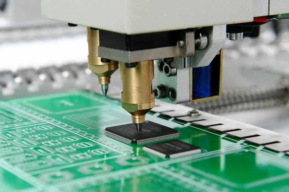
Figure 5: Challenges of Surface Mount Technology (SMT)
Surface Mount Technology (SMT) faces several difficulties, mostly due to the small size of its components and the accuracy needed during manufacturing. One of the biggest issues is rework, which involves removing and replacing components. Because these components are so tiny and close together on the circuit board, rework requires great care to avoid damaging nearby parts or the board itself. This task often needs special tools and skilled workers, which can increase both the time and cost involved.
Another major challenge is the initial cost needed to set up SMT production lines. Unlike older methods like through-hole technology, SMT requires advanced machines for placing components, soldering them, and inspecting the finished products. These machines, such as high-speed pick-and-place machines and reflow ovens, are expensive to buy. Plus, they require a trained workforce to operate and maintain, which adds to the overall cost and time investment.
Applications of Surface Mount Technology
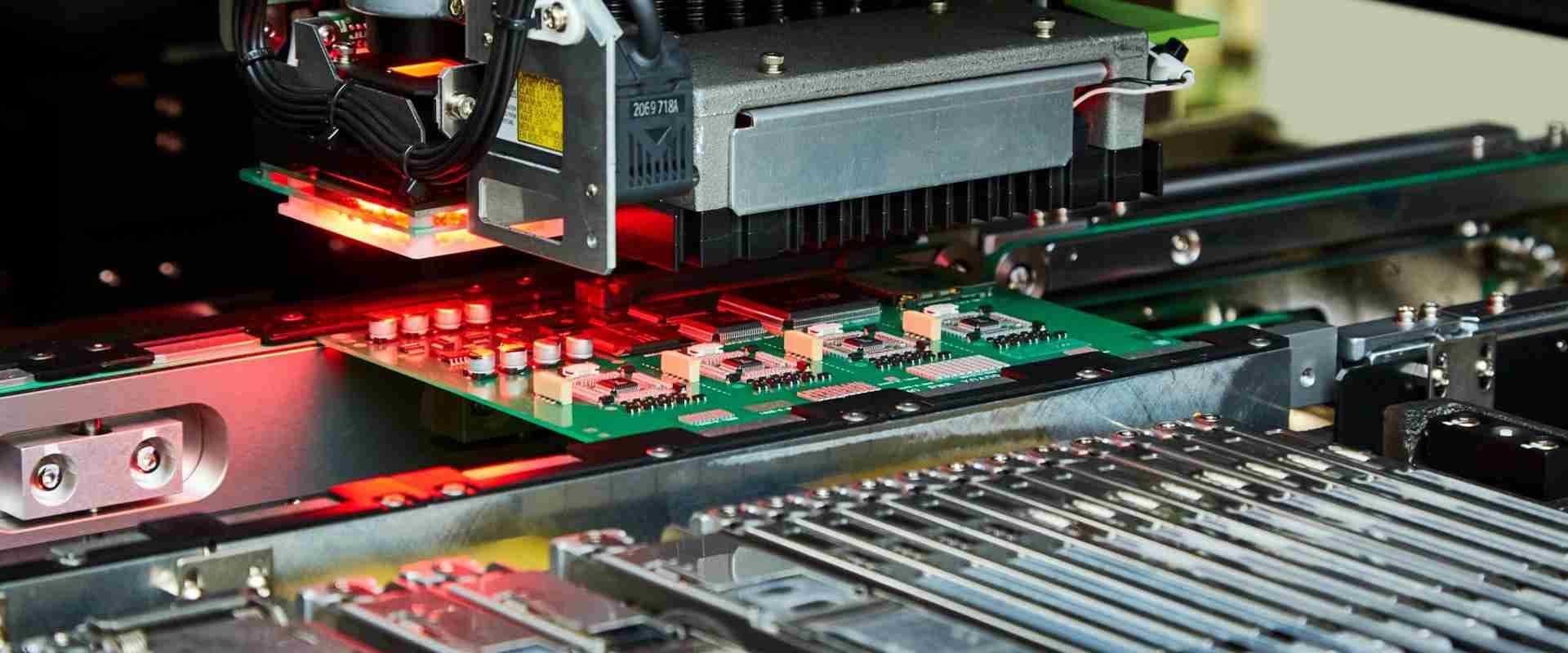
Figure 6: Applications of Surface Mount Technology (SMT)
Surface Mount Technology is widely used in various industries because it allows for the creation of smaller, lighter, and more efficient electronic devices. In consumer electronics, for instance, SMT is used to make products like mobile phones, laptops, and televisions, where saving space and packing in more components is very important. The automotive industry also uses SMT heavily, especially for electronic systems like engine control units (ECUs) and entertainment systems in cars, which need to be reliable and perform well under tough conditions.
In industrial settings, SMT is used to make devices like programmable logic controllers (PLCs) and control panels, which are necessary for automation and managing industrial processes. These devices benefit from the precision and durability that SMT offers, allowing them to work effectively in harsh environments. The medical device industry also depends on SMT for creating advanced equipment like imaging machines and monitoring devices. The ability to produce small, reliable, and high-performance components is very important in medical applications, where accuracy and safety are top priorities.
Differences Between SMD and SMT
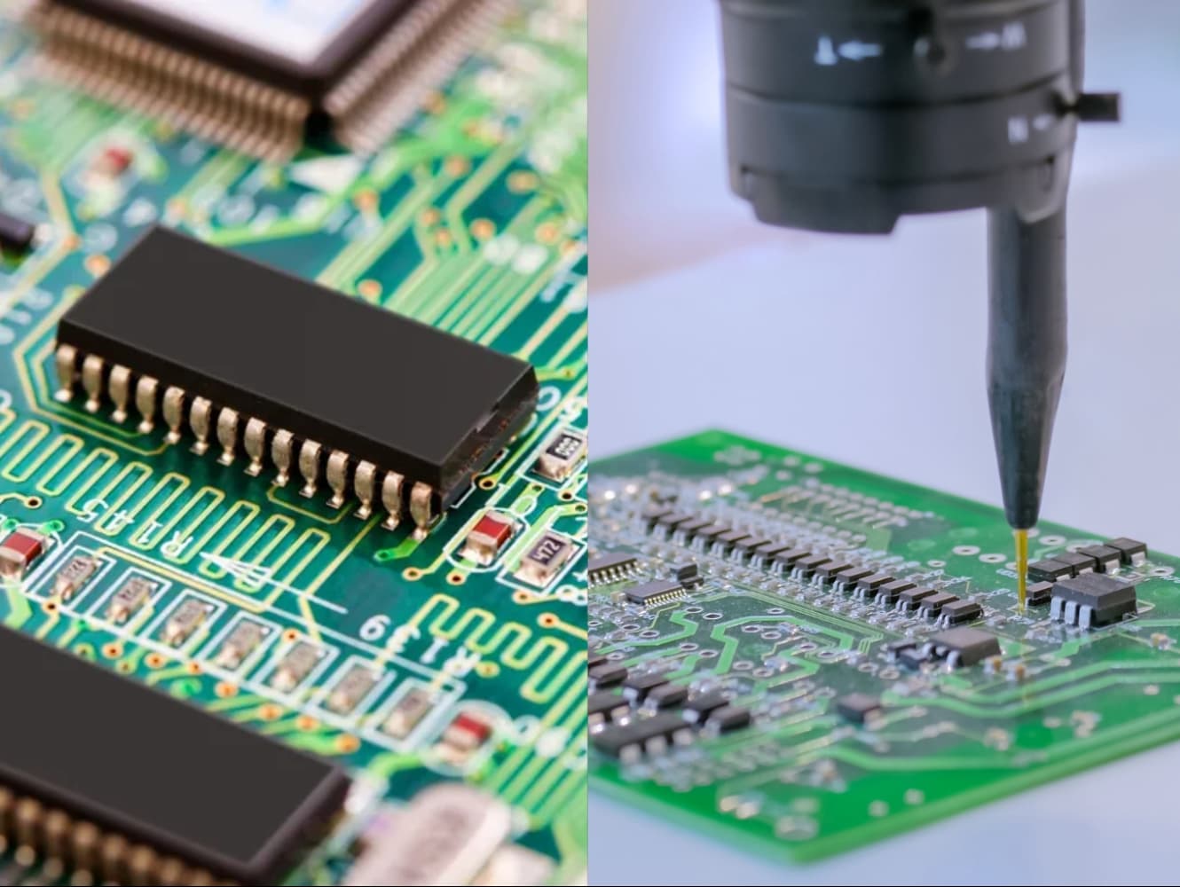
Figure 7: Surface Mount Devices (SMD) and Surface Mount Technology (SMT) in Action
Surface Mount Devices (SMD) and Surface Mount Technology (SMT) are closely related but refer to different parts of the same process. SMT is the entire process of assembling electronic components directly onto the surface of a printed circuit board (PCB). This process includes several steps, such as placing components accurately, soldering them in place, and then testing the final product to make sure it works properly.
On the other hand, Surface Mount Devices (SMD) are the individual electronic parts designed for this type of assembly. Unlike older components that had long leads sticking through holes in the board, SMDs have flat, short leads or terminals that are soldered directly onto the PCB’s surface. SMDs include a variety of components, such as resistors, capacitors, and integrated circuits (ICs), and they are what make modern electronic devices smaller and more efficient. So, while SMT is the overall process, SMD refers to the specific parts used in that process.
Conclusion
Surface Mount Technology (SMT) and Surface Mount Devices (SMDs) have greatly changed how electronics are made, allowing for the creation of smaller, more efficient, and more reliable devices. The move from the old through-hole technology to SMT has helped make electronic components smaller and improved the overall process of making them. Although SMT has some challenges, such as the need for careful work when fixing or replacing parts and the high costs of setting up the machines, the benefits, like faster production, better heat management, and longer-lasting devices, make it the best choice for making large numbers of products. As technology continues to move forward, SMT will keep playing an important role in the future of electronics, making it a topic worth understanding. By learning more about SMT and SMDs, we can better appreciate how the electronic devices we use every day are made.
Frequently Asked Questions [FAQ]
1. What are the advantages of SMT or SMD?
SMT and SMD offer the benefit of making electronic devices smaller and more compact. They allow for faster and cheaper production because machines can be used to place the parts automatically. This method also improves how well the devices work and how long they last. Additionally, SMT allows parts to be placed on both sides of the circuit board, saving space.
2. What are the functions of SMT?
SMT is used to efficiently place electronic parts on the surface of a circuit board. This process helps create smaller, lighter, and more complex electronic circuits. It also speeds up production and lowers costs by allowing machines to handle the assembly.
3. What are surface mount technology SMT components?
SMT components are the small electronic parts designed to be placed on the surface of a circuit board. These include things like resistors, capacitors, inductors, transistors, diodes, and integrated circuits (ICs). These parts have short leads or terminals that are directly soldered onto the board.
4. Why is SMD used?
SMD is used because it helps make electronic devices smaller, more efficient, and more reliable. By using SMDs, the size of electronic circuits can be reduced, which is useful for making compact devices like smartphones and laptops. It also allows for automated assembly, which lowers production costs and ensures consistent quality.
5. What is the difference between SMD and SMT mounting?
SMD stands for Surface Mount Device, which are the small parts used in electronics that are placed on the surface of a circuit board. SMT stands for Surface Mount Technology, which is the method or process used to put these SMD parts onto the board. So, SMD refers to the parts themselves, while SMT is the process of placing them on the board.