Evaluating Power Factor in Electrical Circuits
In the complex field of electrical engineering, the power factor is a key indicator of AC (alternating current) circuit efficiency. Power factor, primarily, quantifies how effectively electrical power is converted into useful work output, delineating the connection between real power, which performs actual work, and apparent power, which encompasses both working and non-working components of electricity. This connection is settling as it directly influences the operational costs, energy efficiency, and reliability of electrical systems, spanning from simple residential setups to complex industrial networks.The core of considerate and optimizing power factors lies not only in enhancing economic efficiency but also in upholding system integrity and environmental sustainability. As such, this article explores various aspects of power factor, from its theoretical underpinnings and calculation methods in different circuit types to strategic correction techniques aimed at mitigating inefficiencies and extending the longevity and capability of power systems.
Catalog
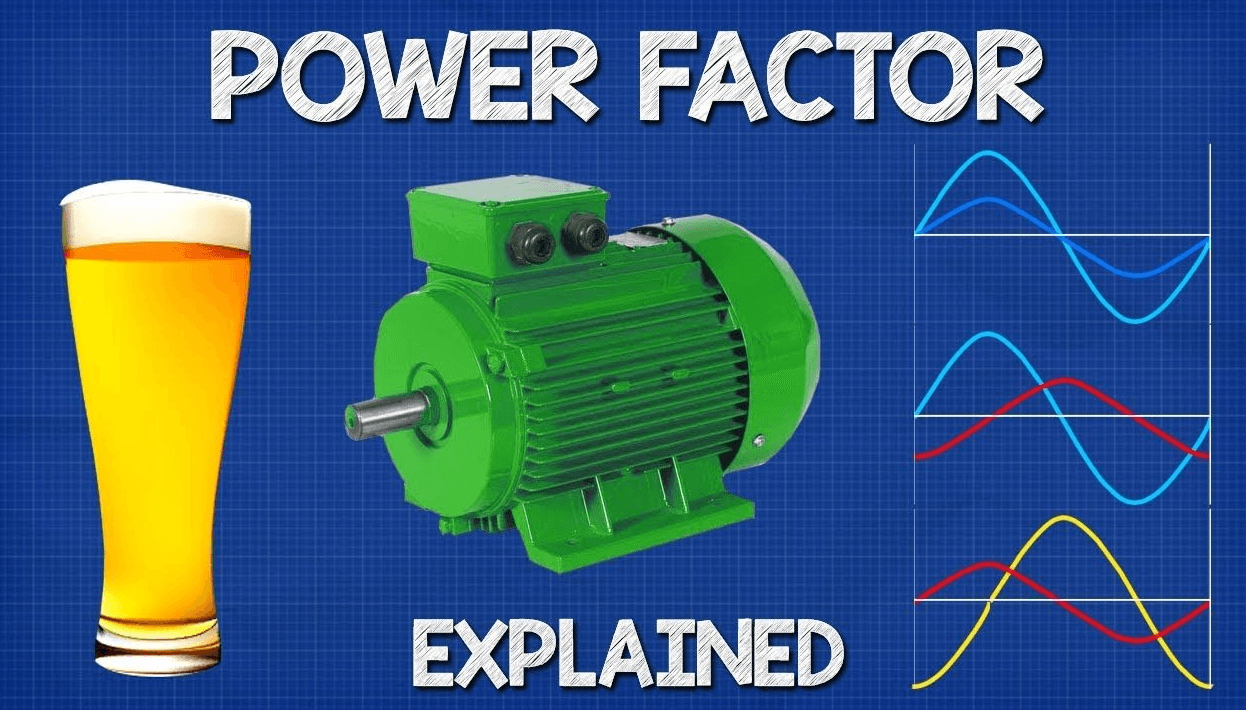
Figure 1: Power Factor Values
Measuring Power Factor Values
Power factor is an unsafe measure for evaluating the efficiency of electrical circuits. Different types of circuits affect their value in distinct ways. In purely resistive circuits, the power factor is 1.0, indicating that current and voltage are perfectly aligned with no phase difference, leading to zero reactive power. This scenario is depicted as a horizontal line in the power triangle. On the other hand, purely inductive or capacitive circuits have a power factor of zero. These circuits do not convert electrical energy into useful work; instead, they store energy temporarily in magnetic fields (inductors) or electric fields (capacitors). This creates a power triangle with a vertical line, showing that reactive power predominates and real power is absent.
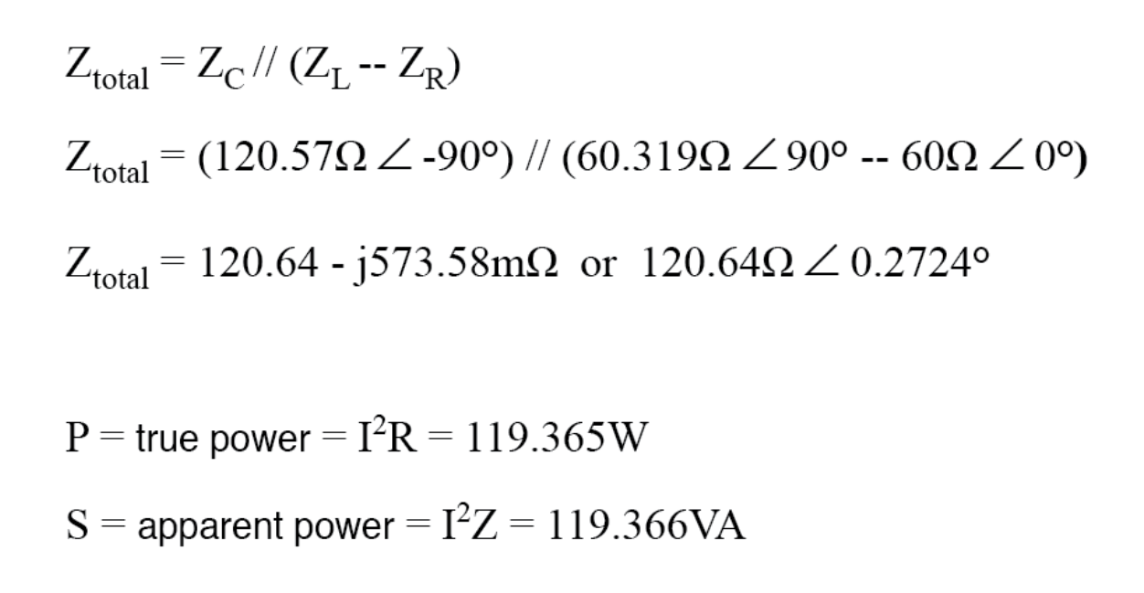
Figure 2: Calculating Power Factor
The power factor measures how efficiently an electrical circuit uses power. It is the ratio of true power (P), which does productive work, to apparent power (S), which includes both real and reactive power. True power is measured in watts (W) or kilowatts (kW), while reactive power (Q), which represents unproductive power circulating in the circuit, is measured in volt-amperes reactive (VAR). The power factor can be calculated using the formula PF = cos(θ), where θ is the phase angle between the current and voltage waveforms. This angle shows how much the current leads or lags behind the voltage. The power factor varies with system characteristics and the frequency of the AC power supply, impacting the efficiency and performance of the electrical system.
For a deeper examination of power dynamics in AC circuits, several formulas are used depending on available system data. The primary formula 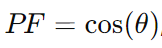 directly measures the efficiency. Another formula
 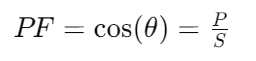 shows the relationship between reactive power and apparent power, indicating how much power is not doing useful work and is contributing to the phase difference. Futhermore,
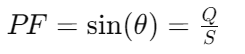 correlates reactive power to true power, providing insights into how reactive power affects overall power consumption.
Figure 3: Power Factor in Single-Phase Circuits
Calculating Power Factor in Single-Phase Circuits
In single-phase residential electrical systems, accurate power factor measurement optimizes energy efficiency and performance.To calculate the power factor (PF), use the formula Here, P is the true power in watts (W), V is the voltage in volts (V), and I is the current in amperes (A).
Calculating Apparent and Reactive Power
To fully understand a circuit's power dynamics, first compute the apparent power using , where S is in volt-amperes (VA). Next, determine the reactive power with the formula
 , where Q is in volt-amperes reactive (VAR). These calculations show how power is distributed within the system, identifying how much power is used for useful work and how much is temporarily stored or lost.
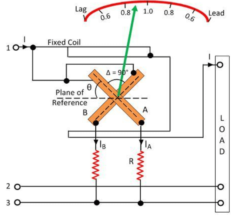
Figure 4: Power Factor in Three-Phase Circuits
Scheming Power Factor in Three-Phase Circuits
In industrial environments with three-phase circuits, accurately measuring the power factor is a must due to the complexity and power capacity of these systems. To calculate the power factor (PF), use the formula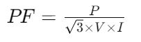 where P is the true power in watts (W), V is the voltage in volts (V), and I is the current in amperes (A). This formula takes into account the unique phase-to-phase voltage relations in three-phase systems.
For a complete power analysis, first calculate the apparent power (S) using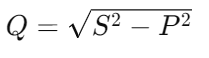 where S is in volt-amperes (VA). Then, determine the reactive power (Q) using the formula with Q measured in volt-amperes reactive (VAR).
The Importance of Maintaining a High-Power Factor
Maintaining a high-power factor is key for optimizing electrical power usage. A power factor close to 1 indicates efficient power use, while a power factor less than 1 means more current is needed to deliver the same amount of true power, signaling inefficiency. This inefficiency leads to higher energy consumption and increased operational costs.
For example, a circuit with a power factor of 0.7 requires more energy to perform tasks than a circuit with a power factor of 1. This inefficiency results in higher energy usage and costs. Improving the power factor is needed not only for cost savings but also for enhancing overall system performance and sustainability.
Efforts to improve power factor often include integrating capacitors or synchronous condensers to offset the lagging current typical in inductive loads. These measures reduce the load on the electricity supply, lower the risk of power surges and drops, and contribute to a more stable power supply.
Implications of a Poor Power Factor
Correcting a poor power factor involves strategically adding capacitors to counteract the reactive power produced by inductive loads. This approach aims to neutralize excess reactive power by generating an equal and opposite reactive force, moving the circuit’s impedance closer to a purely resistive state, which is more efficient. The process includes installing capacitors in parallel with inductive elements. This setup helps align the total impedance with pure resistance, reducing unnecessary power draw. These adjustments significantly enhance the system's energy efficiency.
Optimizing the reactive power balance not only improves efficiency but also extends the lifespan of electrical components. Efficient energy use reduces strain on power systems, minimizes heat generation, and lowers the risk of damage to sensitive equipment. By addressing poor power quality, power factor correction ensures more reliable and stable operation of electrical systems. The improved stability can lead to cost savings in the long run, as the need for maintenance and replacements diminishes.
The Impact of a Low Power Factor on Electrical Systems
A low power factor causes several negative effects on electrical systems, primarily through increased copper losses and poor voltage regulation. These problems arise because more current is needed to deliver the same amount of power, a direct result of power factor inefficiency.
Increased Current and Thermal Burden
Higher current levels increase the thermal load on the circuit's wiring. This can accelerate insulation degradation and heighten the risk of overheating. The elevated current flow also leads to greater voltage drops across the distribution network.
Effects on Device Performance and Lifespan
Voltage drops can significantly impair the performance and reduce the lifespan of electrical devices connected to the grid. Voltage instability affects device efficiency and can trigger protective relays or cause sensitive equipment to fail prematurely.
From an economic perspective, electrical utilities often charge higher rates for consumers with low power factors, reflecting the additional costs utilities incur to manage the excess current required by inefficient systems. By improving power factors, businesses can avoid these surcharges, enhance equipment reliability, and decrease overall operational expenses. Effective power factor correction strategies are significant for both industrial and commercial settings, as they help businesses avoid extra charges, improve device performance, and ensure the reliability and longevity of their electrical systems.
Common Causes of Low Power Factor
Low power factor in electrical systems can be caused by several factors, mainly harmonic currents and inductive loads.
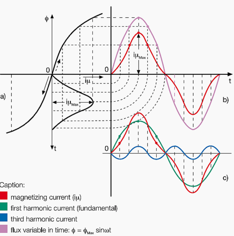
Figure 5: Harmonic Currents
Harmonic Currents, distort the sinusoidal shape of the electrical waveform. This distortion often occurs due to non-linear loads like variable-speed drives and electronic ballasts. These harmonics disrupt the efficient flow of electricity and reduce the power factor.
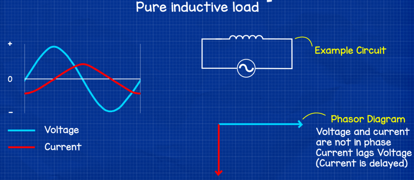
Figure 6: Inductive Loads
Inductive Loads, common in industrial settings, also lower power factor. Devices such as motors, large transformers, and induction furnaces draw reactive power, causing a phase shift between current and voltage. This phase displacement results in less effective power utilization and a decreased power factor.
Figure 7: Power Factor Correction
Strategies for Power Factor Correction
Power factor correction involves placing capacitors or inductors in a circuit to improve the phase alignment between voltage and current, moving the power factor closer to unity. This ideal state allows for efficient energy transfer.
In circuits with inductive loads, such as motors or transformers, capacitors are used to counteract the lagging current. Capacitors provide leading reactive power, which helps balance the phase angle and improve the power factor.
In systems with capacitive loads, inductors are employed to introduce lagging reactive power. This addition balances the leading characteristics of the capacitive loads, aligning the phase angle more closely with pure resistance.

Figure 8: Electrical Loads
Origins of Poor Power Factors in Electrical Systems
Poor power factors stem from the type of load within an electrical system—resistive, inductive, or capacitive. Each load type interacts differently with the alternating current (AC) power source, affecting the system’s efficiency in using power.
• Resistive Loads: Resistive loads, like heaters and incandescent lamps, typically operate at a power factor close to 1. This is because the voltage and current are in phase, resulting in efficient power usage.
• Inductive Loads: Inductive loads, such as motors, transformers, and coils, cause a lag between the voltage and current. This lag leads to a power factor of less than 1. The energy required to establish magnetic fields around inductive components causes this delay.
• Capacitive Loads: Capacitive loads, including certain electronic circuits and capacitors, can make the current lead to the voltage. This also results in a suboptimal power factor.

Figure 9: Heavy Duty Power Factor Correction Capacitors
Enhancing Power Factor with Correction Capacitors
To improve the power factor in AC electrical systems, it needs to address inefficiencies caused by inductive loads such as motors and transformers. These loads create a phase lag between voltage and current, reducing the system's power factor. One effective method to counteract this issue is by integrating power factor correction capacitors. These capacitors introduce a leading phase angle, which neutralizes the lag caused by inductive loads. Capacitors for power factor correction come in various types, including fixed, automatic, and those engineered by manufacturers like ABB.
Capacitors work by offsetting the inductive reactance in the loads with an equivalent capacitive reactance. This improves power efficiency and reduces the burden on the electrical supply. Unlike in DC circuits where power is simply the product of voltage and current, AC circuits must consider reactance, which affects real power consumption due to the cyclical variations in current and voltage.
Figure 10: Power Factor in AC Circuits
Analyzing Power Factor in AC Circuits
The power factor in AC circuits, represented as cos(Φ), measures power usage efficiency by comparing real power (P) to apparent power (S). In an ideal, purely resistive circuit, the power factor is 1.0, meaning no phase difference between current and voltage, and real power equals apparent power. However, most practical AC circuits include inductive or capacitive components, causing phase differences that reduce power efficiency.
A high power factor indicates that most of the power is used for productive work, while a low power factor means substantial power is wasted as reactive power. Reactive power, while not contributing to actual work, is required to maintain the circuit's magnetic and electric fields.
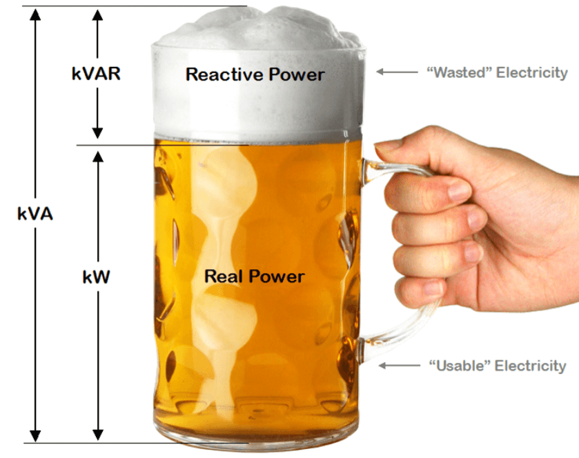
Figure 11: Power Factor Beer Mug Analogy
Power Factor Example
An analogy with a beer mug can help simplify the concept of power factors. The liquid beer represents active power, measured in kilowatts (kW), which is the effective power doing useful work. The foam on top symbolizes reactive power, measured in kilovolt-amperes reactive (kVAR), which doesn’t contribute to productive output but causes heat and mechanical vibrations. The entire mug stands for apparent power, measured in kilovolt-amperes (kVA), reflecting the total power drawn from the energy provider. Ideally, the power used by electrical circuits would match the power supplied, resulting in a power factor of one. However, inefficiencies often cause the demanded power to exceed the supplied capacity, adding strain to the utility infrastructure.
To manage these inefficiencies and maintain stability, utilities impose demand charges on large power users. These charges are based on the highest average load during a specific period, usually between 15 to 30 minutes. This strategy ensures utilities can maintain enough capacity to handle peak loads, which are serious moments when demand hits its maximum and could destabilize the power system if not managed properly. For substantial power users, the entire billing cycle’s charges are often calculated based on these peak usage times. Utilities impose surcharges on consumers with a low power factor, akin to the higher operating costs of an inefficient vehicle. Achieving a power factor of one in alternating current (AC) circuits is rare due to inherent line impedances, leading to unavoidable in.
The Downsides of a Low Power Factor
In alternating current (AC) systems, especially in three-phase circuits, the power factor is a stable parameter. The lower the power factor, the greater the current.
A low power factor increases the current flow, leading to several disadvantages. One primary consequence is higher power losses, calculated by the formula Power Loss = I² x R. For instance, a power factor of 0.8 results in power losses approximately 1.56 times greater than at a power factor of one (unity).
The use of electrical machinery like transformers and switchgear with higher kVA ratings becomes necessary due to increased power losses caused by a lower power factor, resulting in larger and more expensive equipment. This situation also leads to the need for thicker wiring to manage the higher current flow, which in turn escalates infrastructure costs.
Benefits of Optimizing Power Factor
Optimizing the power factor in electrical systems typically involves installing capacitors, using synchronous motors, or employing static VAR compensators. These measures offer several significant benefits.
Increased Efficiency and Cost Savings
Improving the power factor boosts system efficiency by reducing the reactive power component. This directly decreases the total power drawn from the utility grid, leading to lower electricity bills. A better power factor mitigates voltage drops across the system, protecting equipment from potential damage, extending its lifespan, and improving performance. It also allows for the use of smaller, more cost-effective conductors, cutting down on expenses for materials like copper.
Enhanced System Capacity and Reduced Line Losses
Managing the power factor effectively cuts line losses and reduces the size of required electrical machinery. This enhancement in system efficiency is particularly noticeable in high power factor scenarios. It not only lowers operational costs but also increases the power system's capacity to handle additional loads without the risk of overloading.
Compliance and Cost Avoidance
Aligning with utility standards is another advantage, as many service providers impose penalties for low power factors. Maintaining a high power factor can help avoid these penalties, leading to further cost savings.
Environmental Benefits
From an environmental perspective, improving the power factor reduces the energy demand needed to run electrical systems. This decrease in energy consumption lowers greenhouse gas emissions, contributing to more sustainable and environmentally friendly energy use practices.
Conclusion
Conclusively, the mastery of the power factor in electrical systems encapsulates a significant aspect of modern electrical engineering, emphasizing a meticulous balance between theoretical knowledge and practical application. By dissecting the nuances of power factors through advanced mathematical formulas and practical examples, this exploration underscores the pervasive impact of power factors on the efficiency and sustainability of electrical systems. Effective management of power factors not only minimizes operational costs and enhances equipment longevity but also contributes to environmental sustainability by reducing unnecessary energy wastage.
The strategic integration of correction devices such as capacitors and synchronous condensers, modified to specific system needs, serves as a testament to the ingenuity of power engineering. As we continue to confront the challenges posed by energy demands and environmental concerns, the role of optimized power factor remains a cornerstone in the quest for more reliable, efficient, and responsible electrical power systems. The enduring pursuit of improvement in power factors through technology and innovation reflects the broader commitment of the field to adapt and thrive in an ever-evolving energy landscape.
Frequently Asked Questions [FAQ]
1. How to calculate power factor in 3-phase?
The power factor in a three-phase system can be calculated using the formula: 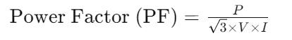 where PPP is the total real power in watts, VVV is the line-to-line voltage in volts, and III is the line current in amperes. This formula assumes a balanced load and does not directly take into account phase angles; for unbalanced loads, measurements for each phase must be used.
2. Why do we calculate the power factor?
Calculating the power factor is key because it helps in assessing the efficiency of the power delivery from the power source to the load. A lower power factor indicates that more current is needed to supply the same amount of power, leading to increased energy losses in the power system. Improving power factors can reduce these losses, decrease electricity costs, and relieve stress on electrical components like cables and transformers.
3. How do you measure the power factor?
Power factor can be measured using a power meter that directly displays the power factor by measuring both the real power (active power) and the apparent power (total power). These meters calculate the phase difference between the voltage and current waveforms to determine the power factor. For more precise industrial applications, specialized power factor meters are used.
4. What is the easiest way to calculate power?
For basic applications, the easiest way to calculate power (specifically, real power) is by using the formula: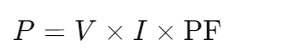 where PPP is power in watts, VVV is voltage in volts, III is current in amperes, and PFPFPF is the power factor. This straightforward method gives a quick estimation of power in circuits where voltage, current, and power factor are known.
5. What are the 3 formulas of power?
Real Power (P):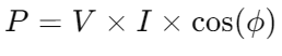 in watts, where
 is the phase angle between the current and voltage.
Apparent Power (S):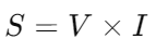 in volt-amperes, representing the total power in the circuit, combining both real and reactive power.
Reactive Power (Q):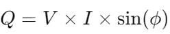 in volt-amperes reactive, which is the power stored in the field of the electrical system and returned to the source in each cycle.
About us
ALLELCO LIMITED
Read more
Quick inquiry
Please send an inquiry, we will respond immediately.
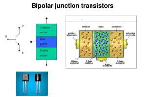
A Complete Guide to Understanding Bipolar Junction Transistors (BJT)
on June 13th
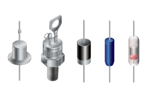
Basics of diode and rectifier
on June 12th
Popular Posts
-

What is GND in the circuit?
on January 1th 2937
-

RJ-45 Connector Guide: RJ-45 Connector Color Codes, Wiring Schemes, R-J45 Applications, RJ-45 Datasheets
on January 1th 2498
-

Fiber Connector Types: SC Vs LC And LC Vs MTP
on January 1th 2089
-

Understanding Power Supply Voltages in Electronics VCC, VDD, VEE, VSS, and GND
on November 9th 1888
-

Comparison Between DB9 and RS232
on January 1th 1760
-

What Is An LR44 Battery?
Electricity, that ubiquitous force, quietly permeates every aspect of our daily lives, from trivial gadgets to life-threatening medical equipment, it plays a silent role. However, truly grasping this energy, especially how to store and efficiently output it, is no easy task. It is against this background that this article will focus on a type of coin cell battery that may seem insignificant on the...on January 1th 1712
-

Understanding the Fundamentals:Inductance Resistance, andCapacitance
In the intricate dance of electrical engineering, a trio of fundamental elements takes center stage: inductance, resistance, and capacitance. Each bears unique traits that dictate the dynamic rhythms of electronic circuits. Here, we embark on a journey to decipher the complexities of these components, to uncover their distinct roles and practical uses within the vast electrical orchestra. Inductan...on January 1th 1651
-

CR2430 Battery Comprehensive Guide: Specifications, Applications and Comparison to CR2032 Batteries
What is CR2430 battery ?Benefits of CR2430 BatteriesNormCR2430 Battery ApplicationsCR2430 EquivalentCR2430 VS CR2032Battery CR2430 SizeWhat to look for when buying the CR2430 and equivalentsData Sheet PDFFrequently Asked Questions Batteries are the heart of small electronic devices. Among the many types available, coin cells play a crucial role, commonly found in calculators, remote controls, and ...on January 1th 1548
-

What Is RF and Why Do We Use It?
Radio Frequency (RF) technology is a key part of modern wireless communication, enabling data transmission over long distances without physical connections. This article delves into the basics of RF, explaining how electromagnetic radiation (EMR) makes RF communication possible. We will explore the principles of EMR, the creation and control of RF signals, and their wide-ranging uses. The article ...on January 1th 1537
-

CR2450 vs CR2032: Can The Battery Be Used Instead?
Lithium manganese batteries do have some similarities with other lithium batteries. High energy density and long service life are the characteristics they have in common. This kind of battery has won the trust and favor of many consumers because of its unique safety. Expensive tech gadgets? Small appliances in our homes? Look around and you'll see them everywhere. Among these many lithium-manganes...on January 1th 1505
HOT Part Number
-

LT1763CDE#TRPBF
Analog Devices Inc.
IC REG LIN POS ADJ 500MA 12DFN
SBL10L30-E3/45
Vishay General Semiconductor - Diodes Division
DIODE SCHOTTKY 30V 10A TO220AC
PIC16F726-E/SS
Microchip Technology
IC MCU 8BIT 14KB FLASH 28SSOP
C1005X5R1E684K050BC
TDK Corporation
CAP CER 0.68UF 25V X5R 0402
PIC18F4580T-I/PT
Microchip Technology
IC MCU 8BIT 32KB FLASH 44TQFP
STK672-340-E
onsemi
IC MOTOR DRIVER UNIPOLAR 12SIP
GRM1885C1E152JA01D
Murata Electronics
CAP CER 1500PF 25V C0G/NP0 0603
AOZ1966DI
Alpha & Omega Semiconductor Inc.
IC REGULATOR DFN
ICL7663SACPA
Renesas Electronics America Inc
IC REG LINEAR POS ADJ 8DIP
MC68EC000FU16
Freescale Semiconductor
MPU, 32-BIT, 16.67MHZ PQFP64
LTC1421ISW#PBF
Analog Devices Inc.
IC HOT SWAP CTRLR GP 24SOIC
FQP2P25
onsemi
MOSFET P-CH 250V 2.3A TO220-3
MAX5069DAUE+
Analog Devices Inc./Maxim Integrated
IC REG CTRLR FWRD CONV 16TSSOP
EPCS16SI16N
Intel
IC CONFIG DEVICE 16MBIT 16SOIC
SPC5606BF1VLU6R
NXP USA Inc.
IC MCU 32BIT 1MB FLASH 176LQFP
ATF-54143-TR1G
Broadcom Limited
FET RF 5V 2GHZ SOT-343
MAX154BCNG
Analog Devices Inc./Maxim Integrated
IC ADC 8BIT FLASH 24DIP
RT0402DRE0762RL
YAGEO
RES SMD 62 OHM 0.5% 1/16W 0402 -
TUSB2046BVFR
Texas Instruments
IC HUB CONTROLLER USB 32LQFP
MBRB60H100CTT4G
onsemi
DIODE ARRAY SCHOTTKY 100V D2PAK
LM258DR2
onsemi
IC OPAMP DUAL LOW POWER 8SOIC
DSPIC33CH64MP203-E/M5
Microchip Technology
IC MCU 16BIT 88KB FLASH 36UQFN
STS8DNF3LL
STMicroelectronics
MOSFET 2N-CH 30V 8A 8-SOIC
SST25VF512A-33-4C-QAE
Microchip Technology
IC FLASH 512KBIT SPI 33MHZ 8WSON
SMCJ18A
Meritek
TVS DIODE 18VWM 29.2VC
SM8S33A-E3/2D
Vishay General Semiconductor - Diodes Division
TVS DIODE 33VWM 53.3VC DO218AB
MS-156HF
Hirose Electric Co Ltd
CONN COAX SWITCH RCPT STR 50OHM
CS5363-DZZR
Cirrus Logic
IC ADC 24BIT SRL 192KHZ 48-LQFP
VS-300CNQ045PBF
Vishay General Semiconductor - Diodes Division
DIODE ARRAY SCHOTTKY 45V TO244
ATMEGA644P-A15AZ
Atmel
IC MCU 8BIT 64KB FLASH 44TQFP
SNJ54HC05J
Texas Instruments
MILITARY 6-CH, 2-V TO 6-V INVERT
STP11NM60FP
STMicroelectronics
MOSFET N-CH 600V 11A TO220FP
MP6906GS-Z
Monolithic Power Systems Inc.
FAST TURN-OFF, INTELLIGENT RECTI
TLC3574IN
Texas Instruments
SAR ADC, 14-BIT, SERIAL ACCESS
LQH31HNR39K03L
Murata Electronics
FIXED IND 390NH 330MA 338MOHM SM
1N5819
NTE Electronics, Inc
DIODE SCHOTTKY 40V 1A DO41 -
C1608C0G2A561K080AA
TDK Corporation
CAP CER 560PF 100V C0G 0603
PT7A7534WE
Diodes Incorporated
IC SUPERVISOR 1 CHANNEL 8SOIC
TMS320F2808ZGMA
Texas Instruments
IC MCU 32BIT 128KB FLASH 100BGA
FAN53610AUC30X
Fairchild Semiconductor
SWITCHING REGULATOR, VOLTAGE-MOD
LTC1451CS8#PBF
Analog Devices Inc.
IC DAC 12BIT V-OUT 8SOIC
SN74HC21NSR
Texas Instruments
IC GATE AND 2CH 4-INP 14SOP
DF3DZ-10P-2H(21)
Hirose Electric Co Ltd
CONN HEADER SMD R/A 10POS 2MM
1812AA151KAT1AJ
KYOCERA AVX
CAP CER 150PF 1KV C0G/NP0 1812
LTM2881CV-3#PBF
Analog Devices Inc.
DGTL ISO 2.5KV RS422/RS485 32LGA
12065C104MA79A
KYOCERA AVX
CAP CER 0.1UF 50V X7R 1206
LT1490AIS8#PBF
Analog Devices Inc.
IC OPAMP GP 2 CIRCUIT 8SO
FDP083N15A-F102
onsemi
MOSFET N-CH 150V 83A TO220-3
51504C
Murata Power Solutions Inc.
CMC 4.1A 2LN TH
TCM320AC54CDW
Texas Instruments
IC COMBO CODEC/FILTER 16SOIC
MC9S08SE4VWL
Freescale Semiconductor
IC MCU 8BIT 4KB FLASH 28SOIC
TPS630242YFFT
Texas Instruments
IC REG BCK BST 3.3V 20DSBGA
FDU8780
Fairchild Semiconductor
MOSFET N-CH 25V 35A IPAK
2540-6002UG
3M
CONN HEADER VERT 40POS 2.54MM