Mastering the Basics of Diodes and Rectifiers
In the rapidly evolving world of electronics, diodes stand as a foundation component, useful for various applications ranging from power conversion to protecting delicate electronic circuits. A diode, primarily, is a device that permits the flow of electrical current in one direction while blocking it in the opposite direction, ensuring components function correctly and safely. Whether it's in simple rectification tasks, protecting against reverse current flow, or ensuring the integrity of high-voltage generators, diodes prove to be a requisite tool in the electronics toolkit. This article digs into the intricate workings of diodes, exploring their physical properties, operational mechanisms, and more.Catalog
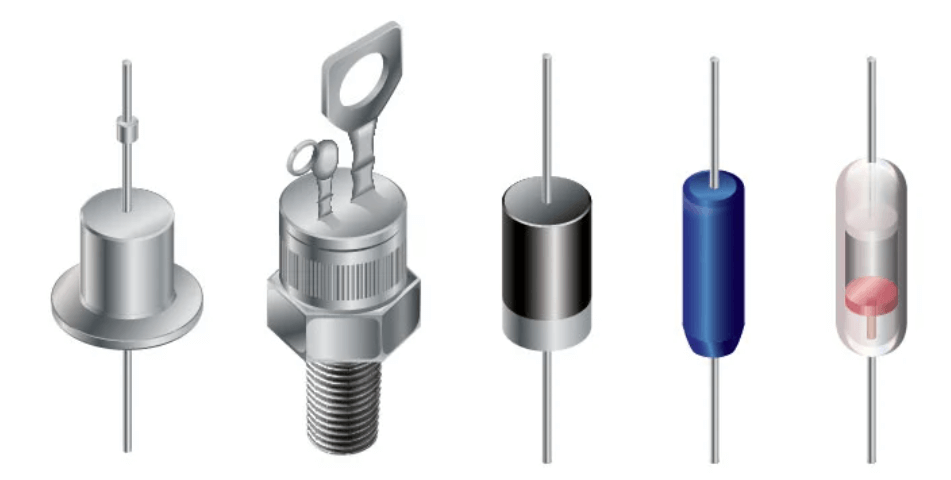
Figure 1: Diodes
Diodes Overview
A diode is a primary electronic component that allows current to flow in one direction while significantly restricting it in the opposite direction. The most common type used in modern electronics is the semiconductor diode. Other important types include Zener diodes and Schottky diodes. In circuit diagrams, diodes are depicted with symbols that show the preferred direction of current flow.
Diodes are classified based on their current handling capacity. Small signal diodes manage currents up to 1 ampere and are suitable for low-power applications like signal modulation. Diodes that handle currents above this level are called rectifiers and are key in power conversion processes.
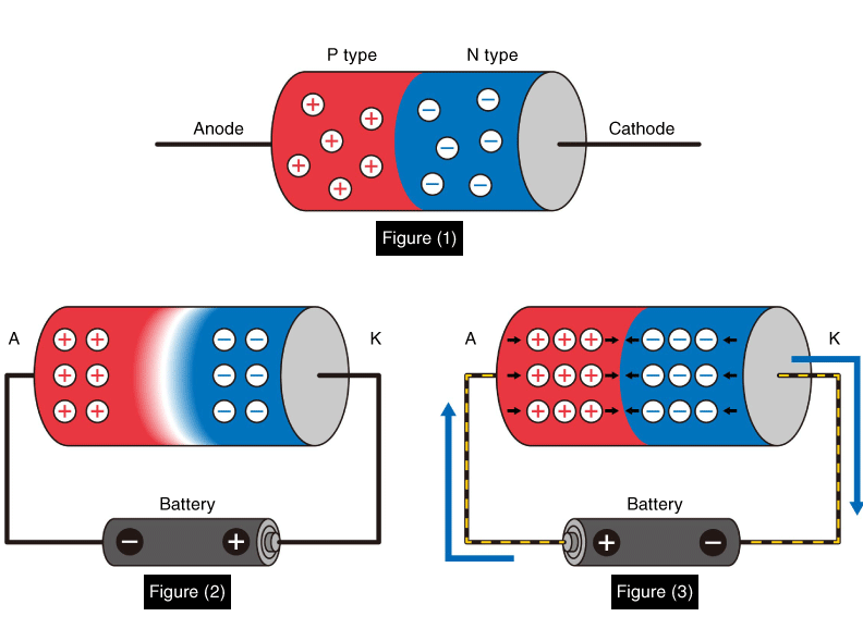
Figure 2: Working Diodes
How Diodes Work?
Think of a diode as a one-way valve for electricity. It allows current to pass only when certain conditions are met. When a diode is forward-biased (meaning the anode is connected to a higher voltage than the cathode), it conducts electricity, completing the circuit and allowing devices like lamps to light up.
When the diode is reverse-biased (the cathode is at a higher voltage than the anode), it stops conducting. This action breaks the circuit and prevents any current flow, effectively stopping any connected devices from operating.
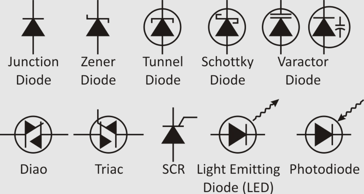
Figure 3: Diodes Symbol and Meaning
Diode Symbols
The symbols for diodes in schematic diagrams help users understand and troubleshoot circuits. The arrow in the diode symbol points in the direction of conventional current flow (from positive to negative), which is the opposite direction of electron flow. This symbolic representation aids in the intuitive understanding of how diodes function within a circuit, ensuring efficient and safe operation.
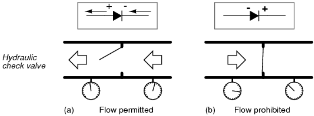
Figure 4: Hydraulic Check Valve Analogy
Hydraulic Check Valves: An Effective Analogy
To better know how diodes work, let's compare them to hydraulic check valves. A hydraulic check valve controls the flow of fluid, allowing it to move in only one direction based on pressure differences. When the pressure on the upstream side is high enough, it overcomes the valve's resistance and lets the fluid through. Similarly, diodes control the flow of electrical current. Voltage differences act like pressure in a hydraulic system. When a diode is forward-biased (the anode is at a higher voltage than the cathode), the voltage "pressure" pushes electrons across the junction, allowing current to flow, similar to a check valve opening to let fluid pass.
In reverse bias (when the cathode is at a higher voltage), the voltage works against the flow of electrons, effectively stopping the current. This is similar to a check valve closing and blocking fluid flow. The behavior of diodes is key for directing current in circuits, protecting sensitive components from reverse currents, and improving the efficiency and safety of electronic systems. The hydraulic check valve analogy helps to visualize diode operations and emphasizes their role in controlling the direction of current. Proper voltage orientation is needed to achieve desired electronic functions and maintain system integrity.
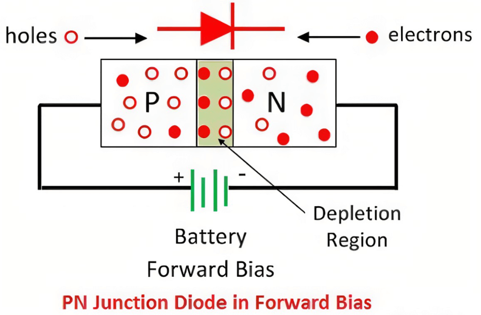
Figure 5: Forward Bias Diode
Exploring the Dynamics of Forward Bias in Diodes
In a forward bias configuration, a diode conducts electrical current effectively with a minimal voltage drop across its junction. This small voltage drop is imperative because it ensures most of the battery's voltage is available for other circuit components, like lamps, thereby improving the system's energy efficiency.
The key to this operation is the behavior of the depletion region at the diode's P-N junction. Without any applied voltage, this region acts as a barrier, preventing electron flow and insulating the diode. When a positive voltage is applied to the anode and a negative voltage to the cathode, the depletion region starts to shrink. The forward voltage reduces the thickness of this barrier until it becomes negligible, allowing electrons to move freely across the junction.
As the barrier thins, electron mobility increases, leading to a steady flow of current. This change within the diode under forward bias is like opening a gate that was previously closed, enabling unrestricted current flow. The efficiency of this process can be compared to a mechanical switch, which might have more resistance and energy loss. In dissimilarity, the diode acts almost like an ideal switch, allowing current flow in the forward-biased state and blocking it when reverse-biased.
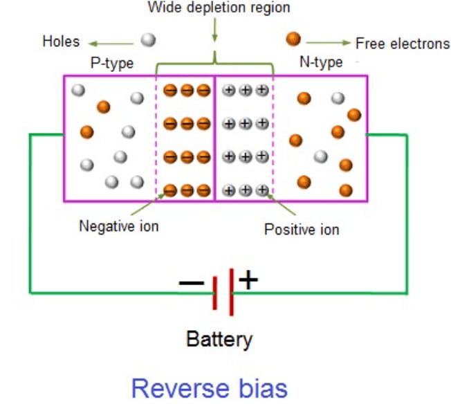
Figure 6: Reverse Bias Diode
Basics of Reverse Bias in Diode Configurations
In reverse-biased mode, a diode acts primarily as a barrier against the electrical current, demonstrating a significant increase in resistance. This resistance occurs due to the expansion of the depletion zone within the diode’s P-N junction when a negative voltage is applied to the anode relative to the cathode. This expansion enhances the diode's ability to obstruct current flow, required in rendering the diode an insulator except for a minor leakage current which is generally inconsequential for most applications.
This configuration is key for safeguarding sensitive components in electronic circuits. The expanded depletion layer forms an effective blockade against reverse currents that might otherwise cause damage or interference by flowing back through the circuit. This protective mechanism is particularly valuable under conditions that could induce electrical stress or lead to component failure, thus maintaining the integrity and functionality of electronic devices.
Furthermore, the Peak Inverse Voltage (PIV) is a serious factor in a diode's reverse-bias operation. PIV, the maximum voltage that a diode can withstand without breakdown, must be carefully considered to ensure the diode's durability and reliability in circuit designs. Temperature fluctuations can influence the PIV, affecting the diode’s ability to resist breakdown under reverse bias. This temperature sensitivity necessitates meticulous selection and management of diodes to ensure consistent and reliable performance across various environmental conditions.
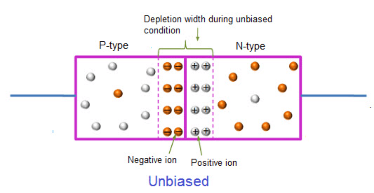
Figure 7: Unbiased Rectifier Diode
Role of Unbiased Rectifier Diodes
An unbiased rectifier diode, also called a non-biased diode, operates without any external voltage or bias. In this neutral state, the diode acts mainly as an open circuit, blocking electrical current flow. This inactive condition remains until the applied voltage exceeds its forward voltage threshold, typically about 0.7 volts for silicon diodes. Below this threshold, the diode restricts significant current flow, making it useful for regulating electrical circuits without external influence.
The functionality of the unbiased rectifier diode is key in electronic systems, especially those designed to prevent accidental current flow. When no voltage is applied, the diode protects sensitive components by blocking electrical transmission. Only with a sufficient forward bias voltage does the diode switch to an "active" state, allowing current to flow in one direction. This selective conduction is key in converting alternating current (AC) to direct current (DC). The diode’s ability to remain non-conductive under certain conditions is needed for the operational stability and efficiency of many electronic devices, highlighting its required role in modern electronic design.
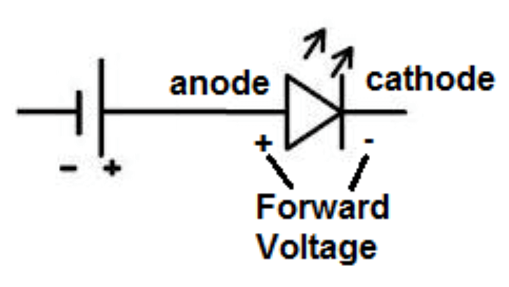
Figure 8: Forward Voltage
Forward Voltage Explained
Forward voltage is a key parameter in diode performance. It represents the minimum voltage needed to activate the diode by reducing the depletion region at its P-N junction. This threshold varies with the semiconductor material used. For instance, silicon diodes typically need about 0.7 volts, while germanium diodes require around 0.3 volts. These values depend on the electrical properties of the materials, influencing the diode's efficiency and suitability for various electronic applications.
The specific forward voltage required is inherent to the semiconductor material. Silicon diodes, needing 0.7 volts, are common in many applications due to their robustness. Germanium diodes, which activate at 0.3 volts, are used in applications needing lower voltage thresholds. Considering these material-specific characteristics helps in selecting the right diode for a given application.
A substantial advantage of diodes is the stability of the forward voltage under varying currents. This stability allows designers to predict the voltage drop across diodes accurately, simplifying circuit design. Consistent forward voltage ensures uniform current flow, which enhances the predictability and functionality of electronic circuits.
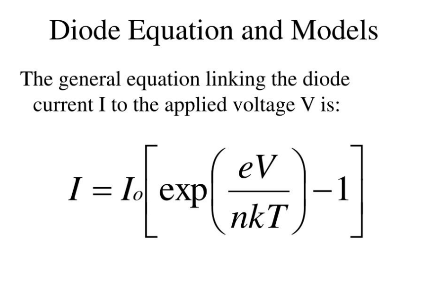
Figure 9: Diode Equation
Unraveling the Diode Equation
The diode equation is required for understanding how current flows through a diode based on the voltage applied. It takes into account the diode's junction temperature and key physical constants, accurately modeling the current response to a given voltage. This relationship is settling for designing circuits that require precise voltage and current control.
Although the diode equation may seem complex, it has significant practical applications, especially in precision-dependent devices like temperature sensors. In these devices, diodes are used to accurately link temperature changes to voltage shifts.
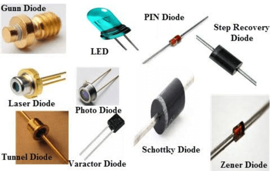
Figure 10: Types Of Diodes
Classifying Diodes: Different Types and Their Functions
Diodes come in various types, each designed for specific functions within electronic circuits. Considering their unique roles enhances circuit performance and reliability.
Rectifier Diodes: Rectifier diodes are built to handle high currents. They convert alternating current (AC) to direct current (DC), making them useful in power supplies and battery chargers.
Switching Diodes: Switching diodes are optimized for rapid operation. They are key in digital and radio frequency (RF) circuits, where fast switching speeds are needed for improved performance.
Zener Diodes: Zener diodes are useful for voltage regulation. They provide a stable reference voltage, ensuring consistent performance in circuits that require precise voltage control.
Light-emitting diodes (LEDs): LEDs convert electrical energy into light. They are used for illumination, signaling, and displays, playing a key role in both practical and decorative applications.
Avalanche Diodes: Avalanche diodes are designed to manage voltage spikes. They protect circuits from transient voltage surges, preventing damage to other components.
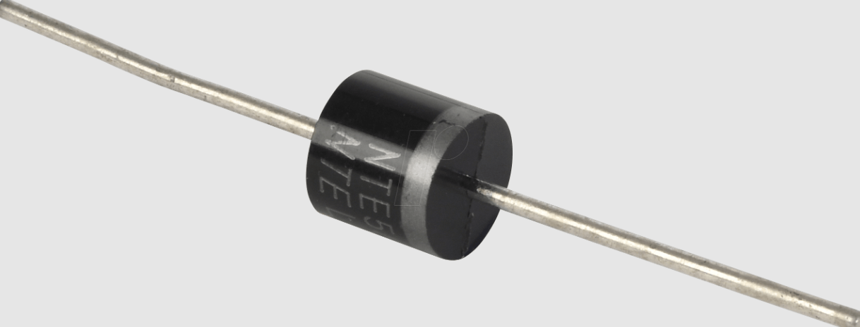
Figure 11: Rectifier
Two Different Types of Rectifiers
Rectifiers are a specialized type of diode designed to convert alternating current (AC) into direct current (DC). Rectifiers come in two main forms: half-wave and full-wave.
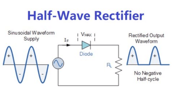
Figure 12: Half-Wave Rectifiers
Half-wave rectifiers allow only one-half of the AC waveform to pass through, blocking the opposite half. This design is simpler and cheaper but less efficient, as it only uses half of the AC cycle.
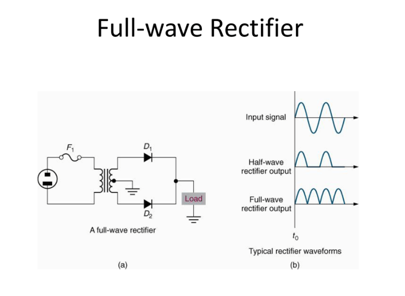
Figure 13: Full-Wave Rectifiers
Full-wave rectifiers utilize the entire AC waveform. They can either use a bridge configuration or a center-tapped transformer to convert the negative half of the AC cycle into a positive one. This approach improves efficiency and output stability.
Exploring the Role of Rectifiers in Electrical Circuit Design
Role in High-Voltage Generators
Rectifiers are influential in developing high-voltage generators, which are needed for applications like early 20th-century particle accelerators. These generators use a series of rectifiers arranged in stages to gradually increase the voltage, demonstrating the rectifier's ability to efficiently manage and amplify high voltages.
Multi-Stage Voltage Increase
In this setup, rectifiers are placed in multiple stages to incrementally step up the voltage. Each stage adds a specific amount of voltage, effectively boosting the overall output. This configuration showcases the rectifier's capability to handle and control high-energy environments. Rectifiers are used in multiple stages, which emphasizes their basic significance in electrical engineering. Rectifiers play a role in high-energy applications because they cannot only convert voltages but also regulate them in intricate systems.
Techniques for Testing Rectifier Diodes
Testing a rectifier diode is required to ensure its effectiveness and reliability in electronic circuits. You can use a multimeter to perform two primary tests: resistance measurement and voltage drop check.
Resistance Measurement
Set your multimeter to the ohmmeter (resistance) setting.
Connect the positive lead of the multimeter to the diode's anode (positive side) and the negative lead to the cathode (negative side). In this forward-biased state, a healthy silicon diode typically shows a resistance that translates to a voltage drop of about 0.7 volts, indicating it functions normally.
Reverse the leads, connecting the positive lead to the cathode and the negative lead to the anode. In this reverse-biased state, the multimeter should read high resistance or display "OL" (over limit), confirming that the diode blocks reverse current effectively.
Voltage Drop Check
Switch the multimeter to its diode check setting, designed to measure the voltage drop across the diode.
Connect the positive lead to the anode and the negative lead to the cathode. The multimeter should show a voltage drop close to 0.7 volts for a silicon diode, which is its typical forward voltage.
Swap the leads, placing the positive lead on the cathode and the negative on the anode. The multimeter should indicate no significant voltage drop, similar to the infinite resistance reading of the ohmmeter test.
Conclusion
As an effective way to regulate current flow and safeguard delicate components, diodes are key to the integrity and operation of electronic circuits. Their diverse types, including rectifier, Zener, and Schottky diodes, cater to a wide range of applications, from power conversion to voltage regulation and signal modulation. The in-depth analysis of forward and reverse bias configurations elucidates how diodes achieve their remarkable efficiency and protective functions.
Frequently Asked Questions [FAQ]
1. What is the principle of diode as a rectifier?
A diode functions as a rectifier by allowing electric current to flow in only one direction—forward. This ability stems from its structure, composed of a semiconductor material forming a junction between two differently doped regions: the P-type and the N-type. When voltage is applied across the diode such that the P-type is connected to the positive side of the voltage source and the N-type to the negative, the diode allows current to pass (forward bias). If reversed (reverse bias), the flow of current is blocked. This selective flow is used to convert alternating current (AC) into direct current (DC).
2. What is the function of the diode?
Beyond rectification, diodes serve several purposes:
Voltage Regulation: Diodes like Zener diodes maintain a constant voltage across electronic components.
Signal Demodulation: Diodes are used in radio and other signal technologies to extract signals from carrier waves.
Protection: Diodes safeguard sensitive electronics by diverting excess voltage (in applications like surge protectors).
3. What is the working point of a diode?
The working point or operating point of a diode refers to the voltage and current conditions at which it operates within a circuit. This point is determined by the intersection of the diode's characteristic curve (showing current vs. voltage behavior) and the load line of the circuit. The working point changes based on the circuit configuration and the applied voltage.
4. What is rectifier importance?
Rectifiers are key for converting AC to DC, which is needed for most electronic devices that require a steady, unidirectional flow of electricity. This conversion is compulsory because many devices, from small electronics to large industrial machines, operate only on DC. Efficient rectification impacts the performance, efficiency, and safety of these systems.
5. What are the characteristics of a diode?
Key characteristics of a diode include:
Forward Voltage Drop: Typically, around 0.7 volts for silicon diodes, this is the voltage required to start conducting current.
Reverse Breakdown Voltage: The maximum reverse voltage a diode can withstand before it starts conducting in reverse.
Current Handling Capability: This determines how much current the diode can safely pass without overheating or being damaged.
Reverse Recovery Time: The time it takes for a diode to cease conducting in reverse once the forward current has been stopped. This is especially imperative in high-frequency circuits.