Discovering Ring Counters: An In-Depth Guide to Their Functionality, Classifications, and Uses
A ring counter is a digital circuit made up of flip-flops connected in a closed loop, enabling sequential and cyclic operations used in digital systems. This article examines ring counters, starting from their basic operation to more complex forms like the 4-bit and 8-bit versions, detailing their initialization, mechanics, and uses.Catalog
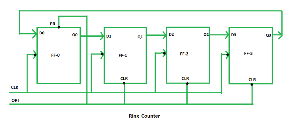
Figure 1: Ring Counter
Basics of Ring Counters
A ring counter is a special kind of shift register, designed in a closed-loop format where the output from the last flip-flop is sent back to the first. This looped arrangement is what sets it apart from standard shift registers, where the data flow stops after the final flip-flop. The operation of a ring counter revolves around a set of flip-flops. The number of states the counter can hold directly depends on how many flip-flops are used in the circuit. For instance, a 4-bit ring counter contains four flip-flops. In practical terms, each flip-flop follows a specific sequence, allowing the ring counter to handle significant tasks like timing and sequencing in digital systems.
In a typical ring counter, a clock pulse (CLK) controls the operation of all flip-flops at the same time, making it a synchronous system. Each flip-flop also has two special inputs—preset (PR) and clear (CLR)—that take priority over other inputs. When the preset input receives a low signal, it forces the flip-flop's output to high. Similarly, when the clear input receives a low signal, it resets the flip-flop's output to low. These preset and clear commands ensure that the outputs remain stable and unaffected by other inputs or clock signals.
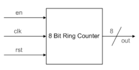
Figure 2: 8-bit Ring Counter
Decoding the 8-bit Ring Counter
An 8-bit ring counter is a digital circuit made up of eight D-type flip-flops arranged in a continuous loop. The output from the eighth flip-flop is fed back into the input of the first, creating an unbroken cycle. This closed-loop design allows the counter to step through a series of distinct states, with each state corresponding to one of the flip-flops being active. The 8-bit configuration can handle a total of eight unique states, which increases the counter’s complexity compared to smaller configurations.
The operation of the 8-bit ring counter begins by setting the first flip-flop to an active state while the remaining flip-flops are inactive. A clock signal is then applied uniformly to all flip-flops, ensuring that state transitions happen at the same time across the entire circuit. As the clock pulses, the active state shifts from one flip-flop to the next in a predictable cycle. This sequential toggling continues until the last flip-flop passes its output back to the first, completing the loop.
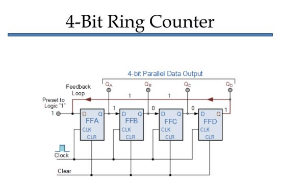
Figure 3: 4-bit Ring Counter
Operating a 4-bit Ring Counter
To operate a 4-bit ring counter, it is typically initialized with a starting state of '0001'. In this setup, the first flip-flop (FF0) is set to output '1', while the other three flip-flops (FF1, FF2, and FF3) are cleared to '0'. This initial configuration ensures that only one flip-flop holds the '1' state, which will then circulate through the rest of the flip-flops with each clock cycle.
As the clock pulses, the '1' shifts from FF0 to FF1, then to FF2, FF3, and eventually back to FF0, creating a repeating loop. This progression continues with each flip-flop taking turns holding the '1' state, while the others remain '0'. This pattern of state changes forms the basic operation of the ring counter, ensuring a predictable sequence as it cycles through all four flip-flops.
To better understand the behavior of the ring counter, waveform simulations using tools like Verilog HDL on platforms such as Xilinx can be helpful. These simulations generate a graphical representation of the counter's state transitions, allowing you to see how the '1' moves from one flip-flop to the next with each clock pulse. For example, during one clock cycle, the '1' shifts from FF0 to FF1, and in the next cycle, it moves to FF2, continuing until it returns to FF0 after reaching FF3. These visual tools are not only helpful for monitoring the sequential shifts but also for confirming the accuracy of the timing and transitions in the design. They offer a clear view of how the ring counter functions, which is suitable for verifying that the device performs correctly in real-world applications.
Deciphering the Truth Table of Ring Counters
A truth table is a serious tool used to map out the input and output states of a ring counter, giving a clear overview of how the counter operates in digital circuits. For a 4-bit ring counter, the table shows how the '1' state moves through each flip-flop output (Q0, Q1, Q2, Q3) in a repeating cycle. The inputs, such as the overriding input (ORI) and clock pulse (CLK), are also listed to show how they affect the state transitions. This table captures the counter’s cyclic behavior, where the '1' progresses from one flip-flop to the next and eventually loops back to the starting point.
In each clock cycle, the '1' shifts from one output to the next, moving from Q0 to Q1, Q1 to Q2, Q2 to Q3, and finally back to Q0. This sequential movement is the essence of how a ring counter functions, and it directly supports the needs of systems that rely on repeated, predictable sequences. Devices like digital watches, rotation sensors, and position encoders all benefit from this cyclical operation, where accuracy and timing are used.
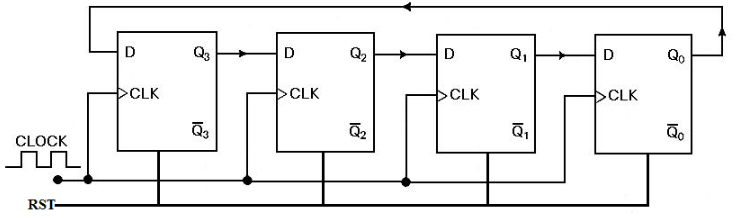
Figure 4: Verilog HDL Program for Ring Counter
Ring Counter Design in Verilog HDL
The following Verilog HDL program is designed to model the behavior of a ring counter using a modular approach. Each module in the code corresponds to a flip-flop in the ring counter, with the output from one module feeding directly into the input of the next. This chain of connections is controlled by rising edge clock pulses, which synchronize the state transitions across all flip-flops, ensuring the system operates in a coordinated manner.
Various Types of Ring Counters
Ring counters come in two main types, each with its unique operational characteristics: the straight ring counter and the twisted ring counter. Both serve different purposes depending on the needs of the digital system.
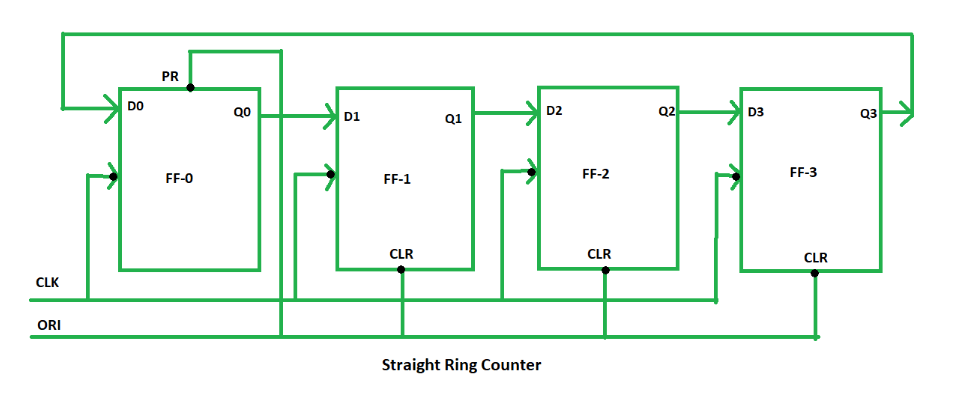
Figure 5: Straight Ring Counter (One-hot Counter)
A straight ring counter, often called a "one-hot" counter, operates by passing a single '1' through a series of flip-flops in a loop. With each clock pulse, the '1' moves to the next flip-flop while all other flip-flops remain at '0'. This simple, cyclic design is ideal for applications that require only one active state at a time, such as basic sequence generators or shift registers. The straightforward nature of the straight ring counter ensures ease of use and reliability in systems where a simple repeating pattern is needed.
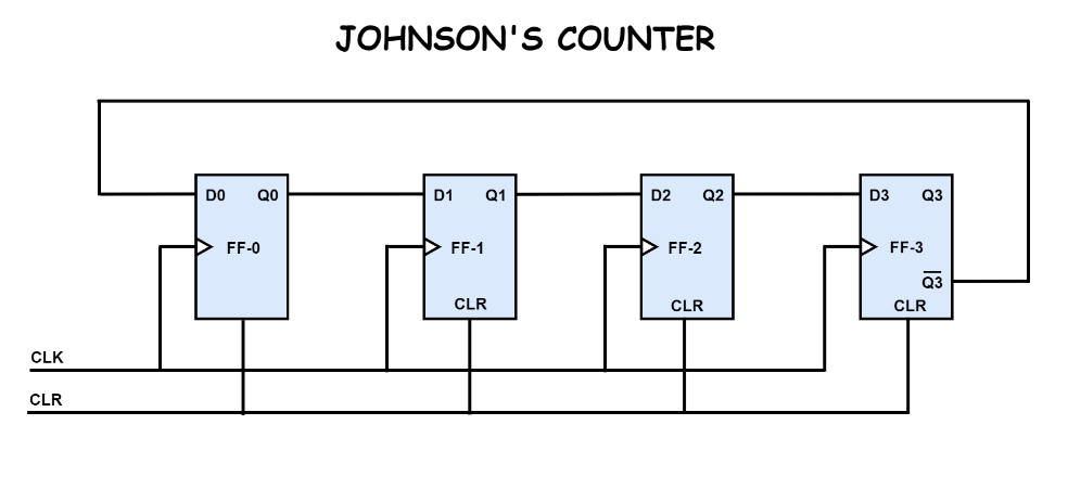
Figure 6: Twisted Ring Counter (Johnson Counter)
The twisted ring counter, also known as a Johnson counter, adds a significant modification to the basic design. In this version, the output of the last flip-flop is inverted before it is fed back into the input of the first flip-flop. This inversion creates a sequence where a series of ones is followed by a series of zeros, effectively doubling the number of distinct states compared to the straight ring counter. As a result, the Johnson counter can handle more complex tasks, making it a better choice for applications that require a wider range of states, such as digital position encoders or more advanced sequencing operations.
Comparing Ring Counters with Johnson Counters
The main difference between a ring counter and a Johnson counter lies in how they handle the feedback loop, which affects the number of states and the overall behavior of each counter.
Ring Counter: In a ring counter, the output from the last flip-flop is fed directly back into the input of the first flip-flop without any changes. Because of this direct loop, the total number of states is equal to the number of flip-flops in the counter. For example, if there are four flip-flops, the counter will cycle through four states. Each flip-flop holds a high ('1') for one clock cycle and stays low ('0') for the rest of the time, creating a simple, repeating sequence of states.
Johnson Counter: A Johnson counter, on the other hand, introduces inverted feedback from the output of the last flip-flop back to the input of the first. This inversion allows the counter to generate more states than the ring counter—doubling the number. Each flip-flop goes through two stages: first, it holds a high ('1') and then a low ('0'), before switching to the opposite state. This means that a four-flip-flop Johnson counter would cycle through eight states. In addition, this design reduces the output frequency, with the output frequency being half that of the input clock signal.
Evaluating the Pros and Cons of Using Ring Counters
Ring counters have distinct benefits and drawbacks that influence their suitability in digital circuit designs.
Pros
Simple Design: One of the main strengths of a ring counter is its straightforward construction. Unlike other counters, it doesn't require additional components like decoders. This simplicity makes it easier and more cost-effective to implement, particularly in systems that need basic encoding or decoding without complex hardware.
Fewer Components: The feedback loop structure of a ring counter allows it to function with fewer components compared to other counter types. This reduction in parts not only lowers costs but also increases reliability, as fewer components mean less risk of hardware failure.
Cons
Limited Number of States: A major limitation of the ring counter is that the number of states is directly tied to the number of flip-flops. If you need more states, you have to add more flip-flops, which may not be practical in applications that demand a larger number of states.
No Self-Starting Capability: Ring counters typically cannot start from any arbitrary state. They need a specific preset condition to begin operating, which can be a disadvantage in systems where flexibility and quick startup are wanted. This means extra steps or components might be required to ensure the counter initializes correctly.
Diverse Applications of Ring Counters in Modern Electronics
Ring counters play a key role in various digital systems, thanks to their simple yet effective cyclic operation. Their ability to move through a fixed number of states in a controlled sequence makes them highly useful across a range of applications.
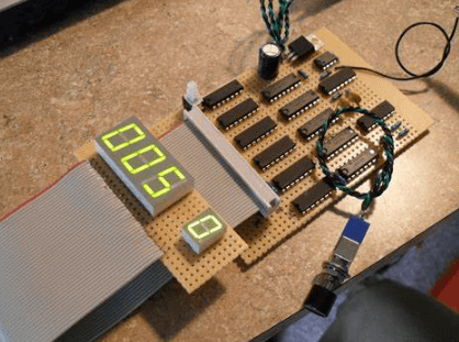
Figure 7: Frequency Counting and Digital Clocks
Ring counters are often used in frequency counters and digital clocks because they can cycle through a set number of states with precision and reliability. This makes them ideal for tasks that require accurate tracking of time or frequency, ensuring stable and predictable operation.

Figure 8: Timers
In timing applications, ring counters are used to measure intervals and trigger specific events. By progressing through their states in sync with a clock signal, they provide a straightforward way to manage timing, ensuring events occur at the right moment based on the counter’s current state.
Figure 9: Finite-State Machines (FSM)
Ring counters are commonly integrated into finite-state machines, particularly in environments like ASIC (Application-Specific Integrated Circuit) and FPGA (Field-Programmable Gate Array) design. Their predictable state transitions make them ideal for controlling the flow of operations in these systems, ensuring each state change is handled smoothly and accurately.
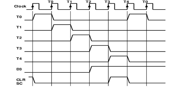
Figure 10: Timing Signals
Ring counters are also valuable for generating timing signals, which are useful for coordinating the operation of more complex circuits. By producing these signals in a regular, cyclic manner, they help ensure different parts of a circuit remain synchronized.
Figure 11: Pseudo-Random Number Generation
In cryptographic systems, ring counters are used to generate pseudo-random numbers, which are dangerous for encryption algorithms. The counters' ability to shift through states predictably while still maintaining randomness in output makes them useful in this sensitive application.

Figure 12: Circular Storage Management
In memory systems, ring counters assist in managing circular queues, ensuring that data is stored and retrieved efficiently. Their cyclic nature allows them to handle the repeated cycling of data in a controlled way, making them ideal for managing buffers and other storage systems that rely on continuous data flow.
Conclusion
Ring counters represent an ultimate yet versatile component in digital circuit design, characterized by their simple construction and effective operation across a multitude of applications. Despite their limitations, such as a fixed number of states and lack of self-starting capability, the simplicity and reliability of ring counters make them requisite in the design of modern digital systems.
Frequently Asked Questions [FAQ]
1. What are the applications of the Johnson counter?
Johnson counters, also known as twisted ring counters, are primarily utilized in digital electronics for creating delay timers and generating symmetric square waveforms. These counters find practical applications in digital clocks for time sequencing, in control systems as divide-by-N counters where they manage sequence operations, and in driving numeric displays where they cyclically produce a set of binary values. Operators often rely on Johnson counters for their simplicity and reliability in producing a high number of states with fewer flip-flops than other counters.
2. What is the classification of a ring counter?
Ring counters are classified based on their operational synchronization:
Synchronous Ring Counter: All flip-flops are driven by a common clock signal, making transitions occur simultaneously across all flip-flops.
Asynchronous (or Ripple) Ring Counter: The output of one flip-flop becomes the clock input for the next, leading to sequential transitions that ripple through the counter.
3. How to use a ring counter?
To use a ring counter effectively:
Initialization: Begin by setting all flip-flops to 0 except for one, which should be set to 1. This setup creates a single '1' that circulates the ring.
Clock Input: Apply a clock pulse. With each pulse, the '1' shifts from one flip-flop to the next in sequence.
Monitoring Outputs: Each flip-flop output can be monitored to track the position of the '1' in the circuit, useful for timing and sequence control
4. Is the ring counter asynchronous or synchronous?
Ring counters can be either synchronous or asynchronous, depending on their design:
Synchronous Ring Counter: All flip-flops change state simultaneously with the clock signal.
Asynchronous Ring Counter: The flip-flops change state sequentially following the activation of the preceding flip-flop, causing a ripple effect.
5. What is the difference between the ring counter and the Jones counter?
The key differences between a ring counter and a Johnson counter are:
Memory Utilization: A ring counter with n flip-flops can represent n states, while a Johnson counter can represent 2n states, making Johnson counters more efficient in terms of state representation per flip-flop.
Circuit Complexity: Johnson counters are more complex as they require additional wiring and setup compared to ring counters.
Output Waveforms: Johnson counters generate a more complex set of output waveforms, which can be advantageous in applications requiring detailed timing patterns, such as in waveform generation in communication systems.
About us
ALLELCO LIMITED
Read more
Quick inquiry
Please send an inquiry, we will respond immediately.
7805 Voltage Regulator
on September 19th
LM741 Op-Amp: Features, Specifications, and Applications
on September 18th
Popular Posts
-

What is GND in the circuit?
on January 1th 2937
-

RJ-45 Connector Guide: RJ-45 Connector Color Codes, Wiring Schemes, R-J45 Applications, RJ-45 Datasheets
on January 1th 2498
-

Fiber Connector Types: SC Vs LC And LC Vs MTP
on January 1th 2088
-

Understanding Power Supply Voltages in Electronics VCC, VDD, VEE, VSS, and GND
on November 9th 1888
-

Comparison Between DB9 and RS232
on January 1th 1759
-

What Is An LR44 Battery?
Electricity, that ubiquitous force, quietly permeates every aspect of our daily lives, from trivial gadgets to life-threatening medical equipment, it plays a silent role. However, truly grasping this energy, especially how to store and efficiently output it, is no easy task. It is against this background that this article will focus on a type of coin cell battery that may seem insignificant on the...on January 1th 1712
-

Understanding the Fundamentals:Inductance Resistance, andCapacitance
In the intricate dance of electrical engineering, a trio of fundamental elements takes center stage: inductance, resistance, and capacitance. Each bears unique traits that dictate the dynamic rhythms of electronic circuits. Here, we embark on a journey to decipher the complexities of these components, to uncover their distinct roles and practical uses within the vast electrical orchestra. Inductan...on January 1th 1651
-

CR2430 Battery Comprehensive Guide: Specifications, Applications and Comparison to CR2032 Batteries
What is CR2430 battery ?Benefits of CR2430 BatteriesNormCR2430 Battery ApplicationsCR2430 EquivalentCR2430 VS CR2032Battery CR2430 SizeWhat to look for when buying the CR2430 and equivalentsData Sheet PDFFrequently Asked Questions Batteries are the heart of small electronic devices. Among the many types available, coin cells play a crucial role, commonly found in calculators, remote controls, and ...on January 1th 1545
-

What Is RF and Why Do We Use It?
Radio Frequency (RF) technology is a key part of modern wireless communication, enabling data transmission over long distances without physical connections. This article delves into the basics of RF, explaining how electromagnetic radiation (EMR) makes RF communication possible. We will explore the principles of EMR, the creation and control of RF signals, and their wide-ranging uses. The article ...on January 1th 1537
-

CR2450 vs CR2032: Can The Battery Be Used Instead?
Lithium manganese batteries do have some similarities with other lithium batteries. High energy density and long service life are the characteristics they have in common. This kind of battery has won the trust and favor of many consumers because of its unique safety. Expensive tech gadgets? Small appliances in our homes? Look around and you'll see them everywhere. Among these many lithium-manganes...on January 1th 1505
HOT Part Number
-

TLV2324IPWR
Texas Instruments
IC CMOS 4 CIRCUIT 14TSSOP
MOC3063XSM
Isocom Components 2004 LTD
OPTOISOLATOR 5.3KV TRIAC 6SMD
SMAJ48A
Taiwan Semiconductor Corporation
TVS DIODE 48VWM 77.4VC DO214AC
NL17SZ14DFT2G
onsemi
IC INVERT SCHMITT 1CH 1-IN SC88A
SP3225EEA-L
MaxLinear, Inc.
IC TRANSCEIVER FULL 2/2 20SSOP
MG200J6ES61
Powerex Inc.
IGBT MOD 600V 200A 1000W
MC34152DR2
onsemi
IC GATE DRVR LOW-SIDE 8SOIC
KSZ8995XA
Microchip Technology
IC 10/100 INTEG SWITCH 128PQFP
NCV1117DT15RKG
onsemi
IC REG LINEAR 1.5V 1A DPAK
VLS2010ET-150M
TDK Corporation
FIXED IND 15UH 400MA 1.476OHM SM
LQP03TG1N0B02D
Murata Electronics
FIXED IND 1NH 600MA 150 MOHM SMD
TL3844P
Texas Instruments
IC REG CTRLR BST FLYBK PWM 8-DIP
QS3861PAG8
Renesas Electronics America Inc
IC BUS SWITCH 10 X 1:1 24TSSOP
TL4050C41QDCKR
Texas Instruments
IC VREF SHUNT 0.5% SC70-5
GRM3196T2A390JD01D
Murata Electronics
CAP CER 39PF 100V T2H 1206
LTC3555IUFD-1#TRPBF
Analog Devices Inc.
IC USB POWER MANAGER 28-QFN
ADG4613BRUZ
Analog Devices Inc.
IC SW SPST-NO/NC 5.1OHM 16TSSOP
ISL6237IRZ
Renesas Electronics America Inc
IC REG CTRLR NOTEBK 4OUT 32QFN -
794955-1
TE Connectivity AMP Connectors
CONN PIN 18-22AWG CRIMP TIN
A3PE3000-FGG484I
Microchip Technology
IC FPGA 341 I/O 484FBGA
1N3167R
Powerex Inc.
DIODE STUD MNT 240A 350V DO-9
SBA120CS_R1_00001
Panjit International Inc.
DIODE SCHOTTKY 20V 1A SOD323
CC1808MKX7RDBB102
YAGEO
CAP CER 1000PF 2KV X7R 1808
HC4P5504B1-5
Intersil
ITU LOW COST, PABX SLIC WITH 40M
PTVS18VS1UR,115
Nexperia USA Inc.
TVS DIODE 18VWM 29.2VC SOD123W
PAM2400AAA300
Diodes Incorporated
IC REG BOOST 3V 400MA SOT23-3
VT281BFCX-ADJ
Analog Devices Inc./Maxim Integrated
IC CHIP SMD
AD8421BRMZ
Analog Devices Inc.
IC INST AMP 1 CIRCUIT 8MSOP
TPS2330IPW
Texas Instruments
IC HOT SWAP CTRLR GP 14TSSOP
SI8512-C-IM
Skyworks Solutions Inc.
SENSOR CURRENT XFMR 10A AC
SMBJ15A-TR
STMicroelectronics
TVS DIODE 15VWM 24.4VC SMB
MMSZ4699T1G
onsemi
DIODE ZENER 12V 500MW SOD123
C1608X7R1A155M080AC
TDK Corporation
CAP CER 1.5UF 10V X7R 0603
KLDR005.T
Littelfuse Inc.
FUSE CARTRIDGE 5A 600VAC/300VDC
BUF634AIDRBR
Texas Instruments
IC OPAMP GP 1 CIRCUIT 8SON
CC0603BRNPO9BN3R3
YAGEO
CAP CER 3.3PF 50V C0G/NPO 0603 -
SDR1806-331KL
Bourns Inc.
FIXED IND 330UH 1A 580 MOHM SMD
SN54128J
Texas Instruments
MILITARY SINGLE 4-INPUT, 4.5-V T
UES2603
Microchip Technology
DIODE GEN PURP 150V 30A TO204AD
IR3596MHA05TRP
Infineon Technologies
IC DC/DC MULTIPHASE CTLR
22-11-1051
Molex
KK2.5MM FL WAF.ASS. GOLD 504505A
CDBA340L-G
Comchip Technology
DIODE SCHOTTKY 40V 3A DO214AC
CSTCW27M0X51-R0
Murata Electronics
CER RESONATOR
ADM101EWARMZ-REEL7
Analog Devices Inc.
IC TRANSCEIVER FULL 1/1 10MSOP
ATXMEGA64B1-AU
Atmel
IC MCU 8/16BIT 64KB FLSH 100TQFP
CC0805JRNPO9BN391
YAGEO
CAP CER 390PF 50V C0G/NPO 0805
UNR5219G0L
Panasonic Electronic Components
TRANS PREBIAS NPN 150MW SMINI3
C2012X7S2A105K125AE
TDK Corporation
CAP CER 1UF 100V X7S 0805
MIC5370-MMYMT-TR
Microchip Technology
IC REG LINEAR 2.8V/2.8V 6TMLF
26LS31/BEA
Rochester Electronics, LLC
DUAL MARKED (5962-7802301MEA)
MRFE6S9135HSR3
NXP USA Inc.
FET RF 66V 940MHZ NI-880S
CD74HC4520M96
Texas Instruments
IC BINARY COUNTR DL 4BIT 16SOIC
S9S08QD4J2MSC
Freescale Semiconductor
IC MCU 8BIT 4KB FLASH 8SOIC
1871058-4
TE Connectivity AMP Connectors
CONN PCI EXP FMALE 164POS 0.039