LM741 Op-Amp: Features, Specifications, and Applications
The LM741 op-amp is a popular and flexible electronic component. This article goes over the pin layout, functions, specs, and different ways the LM741 can be used, while also comparing it to similar models like the LM358.Catalog
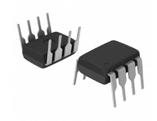
Figure 1: LM741
What Is the LM741 Op-Amp?
The LM741 op-amp improves how circuits work and is better than older models like the LM709. The LM741 is a high-gain amplifier and can be used in many types of circuits, including ones with other models like the 709C, LM201, MC1439, and 748. It has strong protection against overloads, so it works reliably without problems like latch-ups or oscillations. This is great for use in mathematical operations and as a comparator, and it can work with either one or two power supplies.
The LM741 Pin Configuration
|
PIN NAME |
PIN NO. |
I/O |
DESCRIPTION |
|
OFFSET NULL |
1 |
I |
Offset null pin used to eliminate the offset voltage and balance
the input voltages. |
|
INVERTING INPUT |
2 |
I |
Inverting signal input |
|
NON-INVERTING INPUT |
3 |
I |
Non-inverting signal input |
|
V- |
4 |
I |
Negative supply voltage |
|
OFFSET NULL |
5 |
I |
Offset null pin used to eliminate the offset voltage and balance
the input voltages. |
|
OUTPUT |
6 |
O |
Amplified signal output |
|
V+ |
7 |
I |
Positive supply voltage |
|
NC |
8 |
I |
No Connect, should be left floating |
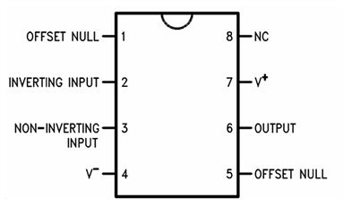
Figure 2: NAB Package 8-Pin CDIP or PDIP Top View
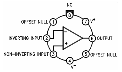
Figure 3: LMC Package 8-Pin TO-99 Top View
The LM741 Pin Functions
• Pin 1: Offset Null
This pin, paired with Pin 5, allows you to fine-tune the output of the op-amp by adjusting the DC offset voltage. When connected to a potentiometer, it helps compensate for any small errors or shifts in the input offset voltage, effectively balancing the output to zero.
• Pin 2: Inverting Input (-)
This pin receives the input signal and inverts it. If the signal at this pin increases, the output decreases, and if the input decreases, the output rises. The relationship between the input and output depends on how the feedback loop is set up. Common in circuits like inverting amplifiers (where the output is the opposite of the input) and in setups that add multiple signals together or process signals mathematically.
• Pin 3: Non-Inverting Input (+)
Signals sent to this pin are amplified and output without being inverted, meaning the output stays in phase with the input. The gain, or how much the signal is amplified, is determined by external resistors connected in the feedback loop of the circuit. Important in circuits where the signal phase needs to stay the same, like in non-inverting amplifiers and voltage followers (help buffer signals).
• Pin 4: V- (Negative Voltage Supply)
Connects to the negative side of the power supply, allowing the op-amp to operate over a full range, in setups that need both positive and negative voltages. Used in dual power supply systems, where the op-amp needs to handle signals that go both above and below zero volts.
• Pin 5: Offset Null
This pin works in conjunction with Pin 1 to adjust the output's DC offset. By tweaking a connected potentiometer, users can calibrate the op-amp to ensure that a zero-volt input results in a zero-volt output, correcting for any minor internal mismatches. Used in calibration circuits to reduce errors in sensitive equipment like test devices and precision instruments.
• Pin 6: Output
This is the pin where the processed, amplified signal is output. It combines the effects of the signals applied at Pins 2 and 3, with the overall behavior depending on the circuit design. The amplified signal is taken from this pin for use in various applications, from simple audio amplifiers to more complex active filters and signal processing systems.
• Pin 7: V+ (Positive Voltage Supply)
Connects to the positive power supply and determines the upper limit of the op-amp’s output. It provides the required voltage for the op-amp to function.
Used in both single and dual power supply circuits to help the op-amp generate output voltages as high as the positive supply allows.
• Pin 8: NC (No Connection)
This pin is not internally connected to any part of the op-amp’s circuitry and has no functional role in the device’s operation. While left unconnected, this pin can occasionally be used for mechanical support, ensuring physical stability when the op-amp is installed on a circuit board.
Specifications of the LM741
|
Parameter |
Device |
Min |
Max |
Unit |
|
Supply voltage |
LM741, LM741A |
- |
±22 |
V |
|
LM741C |
- |
±18 |
V |
|
|
Power dissipation |
- |
500 |
mW |
|
|
Differential input
voltage |
- |
±30 |
V |
|
|
Input voltage |
- |
±15 |
V |
|
|
Output short circuit
duration |
- |
Continuous |
- |
|
|
Operating temperature |
LM741, LM741A |
-50 |
125 |
°C |
|
LM741C |
0 |
70 |
°C |
|
|
Junction temperature |
LM741, LM741A |
150 |
°C |
|
|
LM741C |
- |
100 |
°C |
|
|
Soldering information |
PDIP package (10
seconds) |
260 |
°C |
|
|
CDIP or TO-99 package (10
seconds) |
300 |
°C |
||
|
Storage temperature, Tstg |
-65 |
150 |
°C |
|
ESD Ratings
|
Parameter |
Description |
Test Method |
Value |
Unit |
|
V(ESD) |
Electrostatic discharge |
Human body model (HBM),
per ANSI/ESDA/JEDEC JS-001 |
±400 |
V |
Recommended Operating Conditions
|
Parameter |
Device |
Min |
Nom |
Max |
Unit |
|
Supply voltage (VDD-GND) |
LM741, LM741A |
±10 |
±15 |
±22 |
V |
|
|
LM741C |
+10 |
+15 |
+18 |
V |
|
Temperature |
LM741, LM741A |
-55 |
|
125 |
°C |
|
|
LM741C |
0 |
|
70 |
°C |
Thermal Information
|
Thermal Metric |
LM741 |
Unit |
|||
|
LMC (TO-99) |
NAB (CDIP) |
P (PDIP) |
|||
|
8 PINS |
8 PINS |
8 PINS |
|||
|
RθJA |
Junction-to-ambient thermal resistance |
170 |
100 |
100 |
°C/W |
|
RθJC(top) |
Junction-to -case (top) thermal resistance |
25 |
- |
- |
°C/W |
Electrical Characteristics
|
Parameter |
Test
Conditions |
Min |
Typ |
Max |
Unit |
|
|
Input offset voltage |
RS ≤ 10 kΩ |
TA = 25°C |
- |
1 |
5 |
mV |
|
TAMIN ≤ TA
≤ TAMAX |
- |
- |
6 |
|||
|
Input offset voltage
adjustment range |
TA = 25°C, VS
= ±20 V |
- |
±15 |
|
mV |
|
|
Input offset current |
TA =
25°C |
- |
20 |
200 |
nA |
|
|
TAMIN ≤ TA
≤ TAMAX |
- |
85 |
500 |
|||
|
Input bias current |
TA =
25°C |
- |
80 |
500 |
nA |
|
|
TAMIN ≤ TA
≤ TAMAX |
- |
- |
1.5 |
μA |
||
|
Input resistance |
TA = 25°C, VS
= ±20 V |
0.3 |
2 |
- |
MΩ |
|
|
Input voltage range |
TAMIN ≤ TA
≤ TAMAX |
±12 |
±13 |
- |
V |
|
|
Large signal voltage
gain |
VS = ±15 V, VO
= ±10 V, RL ≥ 2kΩ |
TA = 25°C |
50 |
200 |
- |
V/ mV |
|
TAMIN ≤ TA
≤ TAMAX |
25 |
- |
- |
|||
|
Output voltage swing |
VS = ±15 V |
RL ≥ 10 kΩ |
±12 |
±14 |
- |
V |
|
RL ≥ 2 kΩ |
±10 |
±13 |
- |
|||
|
Output short circuit
current |
TA = 25°C |
- |
25 |
- |
mA |
|
|
Common-mode rejection
ratio |
RS ≤ 10 Ω, VCM
= ±12 V, TAMIN ≤ TA ≤ TAMAX |
80 |
95 |
- |
dB |
|
|
Supply voltage rejection
ratio |
VS = ±20 V to
VS = ±5 V, RS ≤ 10 Ω, TAMIN ≤ TA
≤ TAMAX |
86 |
96 |
- |
dB |
|
|
Transient response -
Rise time |
TA = 25°C, unity gain |
- |
0.3 |
- |
µs |
|
|
Transient response -
Overshoot |
- |
5% |
- |
|||
|
Slew rate |
TA = 25°C,
unity gain |
- |
0.5 |
- |
V/µs |
|
|
Supply current |
TA = 25°C |
- |
1.7 |
2.8 |
mA |
|
|
Power consumption |
VS = ±15 V |
TA = 25°C |
- |
50 |
85 |
mW |
|
TA = TAMIN |
- |
60 |
100 |
|||
|
TA = TAMAX |
- |
45 |
75 |
|||
Features of LM741
Overload Protection: The LM741 has built-in protection on both the input and output to prevent damage from overloads.
Latch-up Prevention: The LM741 is designed to avoid latch-up, even if the common-mode range is exceeded. This means it will keep working properly without needing to be turned off and on again.
Pin Compatibility: The LM741 can directly replace older models like the LM709C, LM201, MC1439, and LM748 in most cases. This makes it easy to swap out parts in existing designs.
Device Operating Modes of LM74
Open-Loop Amplifier: In this mode, the LM741 operates without feedback, meaning it has a very high gain. Small differences between the inverting and noninverting inputs can drive the output close to the supply voltage. When used this way, it acts like a comparator: if the noninverting input is positive, the output will be positive, and if it's negative, the output will be negative.
Closed-Loop Amplifier: In this configuration, negative feedback is used to control the gain. This reduces the gain compared to the open-loop mode and allows the overall behavior of the circuit to depend on the feedback network instead of just the amplifier itself. The circuit's response is determined by the transfer function.
LM741 Circuit Applications
Incorporating the LM741 into circuits unlocks several practical applications:
• Voltage Follower
In a voltage follower setup using the LM741 operational amplifier, the output voltage matches the input voltage. This configuration ensures that the amplifier has a high input impedance and low output impedance that helps protect the source from being influenced by the load in later parts of the circuit. It's commonly used to keep signals accurate in a circuit, making sure the input signal isn’t weakened by other components.
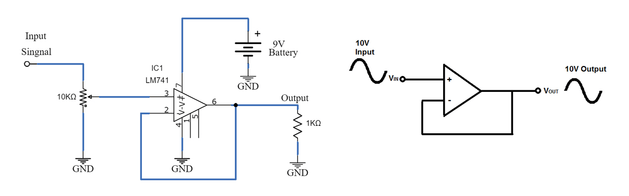
Figure 4: Voltage Follower Circuit using Op-Amp LM741
• Unity Gain Inverting Amplifier
A unity gain inverting amplifier with the LM741 flips the phase of the input signal without changing its strength. This is useful in areas like sound systems, where it helps correct phase issues or create specific effects by reversing the signal. Audio equipment often uses this setup to fix or manage the phase alignment in different sound channels.
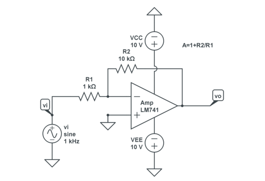
Figure 5: Unity Gain Circuit of LM741
• Bilateral Current Source
The LM741 can act as a bilateral current source, providing a steady current that doesn't change even if the direction of the load shifts.
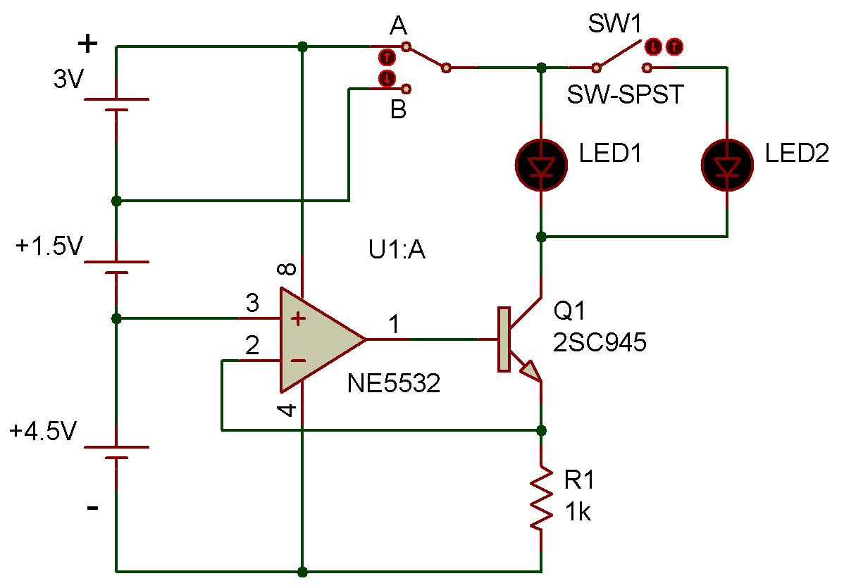
Figure 6: LM741 Op-Amp Constant Current Source
• AC to DC Converter
In AC to DC conversion, the LM741 helps change alternating current (AC) into direct current (DC). The amplifier smooths out the fluctuating AC signal to prevent disruptions or potential damage to electronic devices.
• Instrumentation Amplifier
When several LM741 amplifiers are combined, they can form an instrumentation amplifier that is used to boost small signals with high accuracy. These amplifiers are used in medical equipment, like ECG or EEG machines, and in industrial sensors to measure small changes in things like pressure or strain without affecting the original signal.
• Square Wave Generator
The LM741 can be configured to create square waves, and used in digital electronics and timing circuits. These waves help keep other circuits or devices in sync by providing regular, precise timing signals.
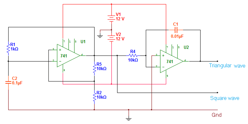
Figure 7: Waveform Generator using LM741
• Voltage Comparator
As a voltage comparator, the LM741 compares two input voltages and produces an output that shows which one is higher. This is useful in systems like battery chargers or power supplies, where the comparator monitors voltage levels to ensure proper operation and stable output.
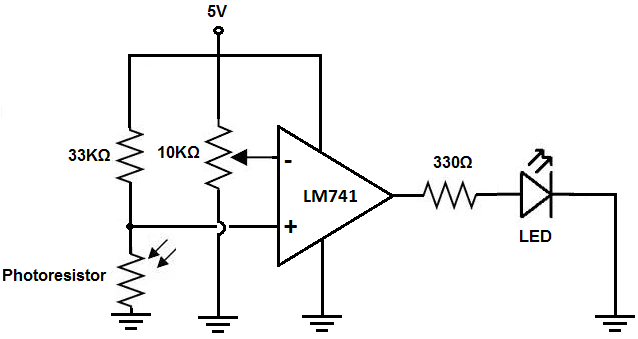
Figure 8: LM741 Op-Amp as a Comparator
• Power Supply Regulation
In power supplies, the LM741 helps regulate and stabilize the voltage, making sure the output stays steady even if the load or input voltage changes.
• Oscillator Circuits
The LM741 can be used in oscillator circuits to produce different types of repeating signals, like sine waves or square waves.
• Half-Wave Rectifier
The LM741 can be part of a half-wave rectifier that converts AC to DC by only processing one half of the AC signal. This simple design is used in low-power applications that don’t require high efficiency, offering an easy way to power devices from an AC source.
LM741 Equivalents and Alternatives
UA741: This op-amp is a close match to the LM741, with almost identical specifications.
MC1741: Another direct replacement, the MC1741 offers compatible performance and the same pinout as the LM741.
TBA221: This model provides similar performance characteristics and can be used as a straightforward substitute.
LM741A: A variant of the LM741, the LM741A offers improved noise reduction and slightly better accuracy.
LM741C: This version offers enhanced stability across a wider range of operating conditions while maintaining the same general performance as the LM741.
TL081: This op-amp features JFET inputs, and offer higher input impedance and lower bias current, well-suited for precision analog circuits.
OP07: Known for its ultra-low input offset voltage, the OP07 is ideal for precision instrumentation and measurement systems.
CA3140: With a MOSFET input stage, this model provides extremely high input impedance and very low bias current, excellent for sensor interfacing.
NE5534: This low-noise, high-performance op-amp is favored in audio applications due to its better stability and wider bandwidth.
LM201: A more advanced version, this op-amp is suited for single-supply operations and offers full overload protection.
MC1439: Very similar to the LM741, the MC1439 may provide better frequency response.
LM748: This alternative offers comparable functionality but includes adjustable frequency compensation, that can be fine-tuned for specific applications.
LM741 Advantages
- Stability
- Offset Adjustment Capability
- High Input Impedance
- Cost-Effectiveness
- Wide Operating Voltage Range
- Reasonable Frequency Response
- Compatibility with Other Op-Amps
How does LM741 Working?
The LM741 operational amplifier operates by using both positive and negative voltage from its power supply. It has two inputs: the non-inverting input (+), where an increase in input voltage causes the output voltage to rise, and the inverting input (-), where an increase in input voltage causes the output voltage to fall. The amplifier works by boosting the difference between the voltages at these two input pins. A feedback loop, usually connected from the output to the inverting input, is often used to control how much the signal is amplified.
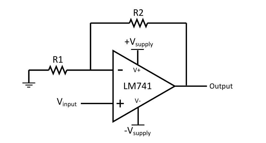
Figure 9: LM741 Circuit Program
Inverting Op-amp
In the inverting configuration, the input signal is applied to the inverting terminal of the op-amp, (pin 2). Meanwhile, the non-inverting terminal (pin 3) is connected to ground or a reference voltage. A feedback resistor is connected between the output (pin 6) and the inverting input (pin 2). This setup causes the output signal to be an inverted version of the input. When a positive voltage is applied to the inverting input, the output becomes negative, and when a negative voltage is applied, the output becomes positive.
The amount of amplification, or gain, that the inverting op-amp provides depends on the ratio between two resistors: the feedback resistor (Rf) and the input resistor (R1). The gain is calculated using the formula:
![]()
For example, if ![]() is 10kΩ and R1 is 1kΩ, the op-amp will have a gain of -10. This means the output will be ten times the input's amplitude but with the opposite polarity (inverted).
is 10kΩ and R1 is 1kΩ, the op-amp will have a gain of -10. This means the output will be ten times the input's amplitude but with the opposite polarity (inverted).
Non-inverting Op-amp
In the non-inverting configuration, the input signal is applied to the non-inverting terminal, (pin 3). The inverting terminal (pin 2) is connected to the output through a feedback resistor, while the input is fed directly into the non-inverting terminal. In this setup, the output retains the same polarity as the input, meaning a positive input voltage produces a positive output, and a negative input results in a negative output.
The gain in the non-inverting configuration is determined by the same two resistors (Rf and R1), but the formula differs:
![]()
For example, if Rf is 10kΩ and R1 is 1kΩ, the op-amp will have a gain of 11. This means the output will be 11 times larger than the input but it will keep the same polarity as the input signal.
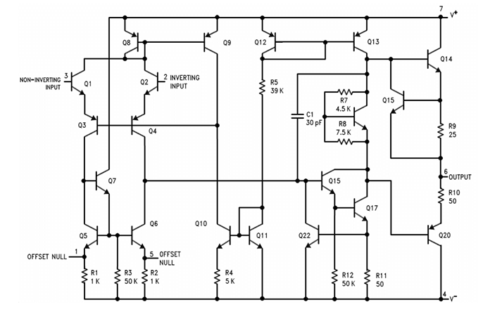
Figure 10: LM741 Functional Block Diagram
How to Connect the LM741 Op-Amp Chip to a Circuit?
To connect the LM741 Op-Amp for a 10x amplification, first, connect the positive power supply (+15V) to pin 7 and the negative power supply (-15V) to pin 4. These are the power connections required for the op-amp to function. Next, connect the input signal to pin 2 (the inverting input) that will invert the output signal. For the feedback loop, place a resistor (Rf) between pin 6 (the output) and pin 2. This resistor helps control the amplification level. At the same time, connect pin 3 (the non-inverting input) to ground to provide a stable reference voltage.
The gain of the amplifier is determined by the ratio of Rf (the feedback resistor) to Rin (the resistor between the input signal and ground), following the formula: ![]() . To achieve a gain of 10, set Rf to 10 times the value of Rin. For example, if Rin is 1kΩ, then Rf should be 10kΩ. The amplified, inverted output can then be taken from pin 6. After everything is connected, power the circuit and test it by inputting a signal. The output should be 10 times the input signal, but inverted. You can adjust the gain as needed by modifying the values of Rf and Rin.
. To achieve a gain of 10, set Rf to 10 times the value of Rin. For example, if Rin is 1kΩ, then Rf should be 10kΩ. The amplified, inverted output can then be taken from pin 6. After everything is connected, power the circuit and test it by inputting a signal. The output should be 10 times the input signal, but inverted. You can adjust the gain as needed by modifying the values of Rf and Rin.
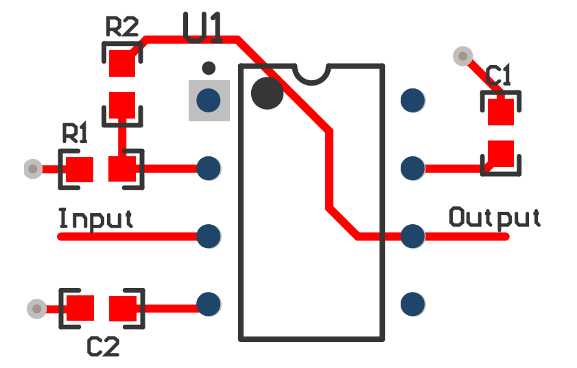
Figure 11: LM741 Layout
How to Safely Long Run LM741 in Circuit?
First, make sure the voltage stays between ±10 and ±22 volts (or 20 to 44 volts total). Going outside this range can damage the amplifier or cause it to not work properly. Also, it's require to control power use. Keep it under 500 mW using the formula P = V × I, where V is the supply voltage and I is the current. Staying under this limit will help avoid overloading the amplifier and make it last longer.
To reduce noise and instability, place a 0.1 µF decoupling capacitor near the power pins. This will help filter out unwanted noise, stabilize the amplifier, and stop annoying oscillations, making sure it runs smoothly. It’s also required to control the temperature around the amplifier. Keep the temperature between -55°C and +125°C, as too hot or too cold could cause problems with how the amplifier works.
If your amplifier is running close to its power limits, you should add heat sinks or other cooling options, if the space is small or doesn’t have good airflow. A clean and compact circuit design also helps. Shorter connections between parts reduce interference and signal loss, improving both performance and durability.
Finally, do regular checks. Look for any signs of wear, like discoloration on the board or the amplifier, and pay attention to the output signals for any strange changes. These might be early signs that the components are starting to wear out. Following these steps, will keep your amplifier safe and work well for a long time.
Comparing the LM741 to the LM358
|
Feature |
LM741 |
LM358 |
|
Supply Voltage |
±15V to ±22V |
3V to 32V (single supply) or ±1.5V to ±16V (dual supply) |
|
Input Bias Current |
~80 nA |
~45 nA |
|
Input Offset Voltage |
~1 mV |
~2 mV |
|
Bandwidth |
1 MHz |
700 kHz |
|
Slew Rate |
0.5 V/μs |
0.3 V/μs |
|
Power Efficiency |
Moderate |
High |
|
Precision |
High (due to lower offset and bias current) |
Moderate (acceptable for general applications) |
|
Applications |
High-voltage, high-precision circuits (e.g., sensor interfaces,
control systems) |
Low-power, low-speed circuits (e.g., battery-powered devices,
everyday electronics) |
LM741 Packaging Options
The LM741 operational amplifier comes in different packaging options, each suited to specific uses and manufacturing needs:
TO-99 (Metal Can): This package is made of strong metal, giving it great heat resistance and durability. It can handle high temperatures and physical stress. The metal also protects against electromagnetic interference (EMI), that helps keep the device stable in environments with a lot of electrical noise.
CDIP (Ceramic Dual In-line Package): The CDIP has a ceramic body that offers better heat and electrical isolation compared to plastic. This makes it ideal for precise applications like scientific instruments and measurement devices. The ceramic material also protects the device from things like moisture and temperature changes, ensuring reliable performance. Its durability helps prevent problems that could shorten the device’s life.
PDIP (Plastic Dual In-line Package): The PDIP is popular in consumer electronics because it's affordable and easy to use in circuit boards. It's designed for automated manufacturing, and helping to keep production costs low. While plastic isn't as strong as metal or ceramic, it works well for everyday electronics like home and office devices where extreme conditions aren't an issue.
Conclusion
The LM741 operational amplifier is a reliable and versatile component in electronics. Its performance in areas like input offset voltage, slew rate, and power consumption, combined with its flexibility in open-loop and closed-loop configurations, makes it a preferred choice for designers. The LM741’s adaptability, ease of integration, and features such as overload protection and high input impedance highlight its enduring relevance and offers guidance for future innovations in amplifier design.
Frequently Asked Questions [FAQ]
1. Can the LM741 be used as an audio amplifier?
Yes, the LM741 can be used as an audio amplifier, although it's not ideal for high-quality audio applications due to its limitations in bandwidth and noise performance. In practical use, an LM741 can amplify low-power audio signals well enough for basic applications, such as small personal projects or educational purposes. When set up as an audio amplifier, one would configure it in a non-inverting or inverting gain setup, connecting input audio to one of the op-amp's inputs and setting the gain with external resistors.
2. What is the minimum voltage for LM741?
The LM741 requires a minimum supply voltage of ±5V to operate correctly, but it performs better at higher voltages, up to ±15V or ±18V. In practice, operating at the minimum supply voltage may limit the dynamic range and headroom of the op-amp, potentially leading to increased distortion or clipping in audio applications.
3. How many transistors are in LM741?
The LM741 contains 20 transistors. These transistors are used in various stages within the op-amp, including differential input stages, gain stages, and output stages. This internal configuration is used for the op-amp's functionality, influencing its gain, bandwidth, and overall performance.
4. What is the maximum frequency of LM741?
The LM741 has a gain-bandwidth product of 1 MHz. This means the maximum frequency at which the op-amp can operate effectively depends on the gain at which it is configured. For example, at a gain of 10, the maximum frequency would be around 100 kHz. Beyond this frequency, the gain starts to roll off, affecting the amplifier's ability to handle higher frequencies accurately.
5. What is the output resistance of LM741 op-amp?
The output resistance of the LM741 is around 75 ohms. This value is important when considering the load that the op-amp can drive without loss of signal strength or distortion. Lower output resistance is better for driving heavier loads.
6. Which is better LM741 or UA741?
Both the LM741 and UA741 are very similar, as the UA741 is often considered a direct equivalent to the LM741. The choice between them comes down to specific manufacturer variations such as slight differences in offset voltage, bias current, or other parameters. For most standard applications, either can be used interchangeably. However, the specific selection might depend on availability, pricing, or minor specification differences.
7. What is the power consumption of LM741?
The power consumption of the LM741 depends on the supply voltage and conditions of operation. The quiescent power consumption (the power consumed when the op-amp is active but not driving a load) is about 85 mW at ±15V supply. This power consumption increases with the output load and frequency of operation.
About us
ALLELCO LIMITED
Read more
Quick inquiry
Please send an inquiry, we will respond immediately.
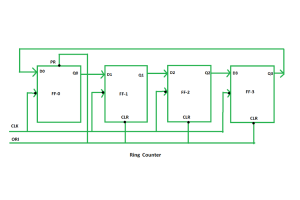
Discovering Ring Counters: An In-Depth Guide to Their Functionality, Classifications, and Uses
on September 18th
JRC4558 Op-Amp: Features, Specifications, and Applications
on September 18th
Popular Posts
-

What is GND in the circuit?
on January 1th 2937
-

RJ-45 Connector Guide: RJ-45 Connector Color Codes, Wiring Schemes, R-J45 Applications, RJ-45 Datasheets
on January 1th 2498
-

Fiber Connector Types: SC Vs LC And LC Vs MTP
on January 1th 2089
-

Understanding Power Supply Voltages in Electronics VCC, VDD, VEE, VSS, and GND
on November 9th 1888
-

Comparison Between DB9 and RS232
on January 1th 1761
-

What Is An LR44 Battery?
Electricity, that ubiquitous force, quietly permeates every aspect of our daily lives, from trivial gadgets to life-threatening medical equipment, it plays a silent role. However, truly grasping this energy, especially how to store and efficiently output it, is no easy task. It is against this background that this article will focus on a type of coin cell battery that may seem insignificant on the...on January 1th 1712
-

Understanding the Fundamentals:Inductance Resistance, andCapacitance
In the intricate dance of electrical engineering, a trio of fundamental elements takes center stage: inductance, resistance, and capacitance. Each bears unique traits that dictate the dynamic rhythms of electronic circuits. Here, we embark on a journey to decipher the complexities of these components, to uncover their distinct roles and practical uses within the vast electrical orchestra. Inductan...on January 1th 1651
-

CR2430 Battery Comprehensive Guide: Specifications, Applications and Comparison to CR2032 Batteries
What is CR2430 battery ?Benefits of CR2430 BatteriesNormCR2430 Battery ApplicationsCR2430 EquivalentCR2430 VS CR2032Battery CR2430 SizeWhat to look for when buying the CR2430 and equivalentsData Sheet PDFFrequently Asked Questions Batteries are the heart of small electronic devices. Among the many types available, coin cells play a crucial role, commonly found in calculators, remote controls, and ...on January 1th 1548
-

What Is RF and Why Do We Use It?
Radio Frequency (RF) technology is a key part of modern wireless communication, enabling data transmission over long distances without physical connections. This article delves into the basics of RF, explaining how electromagnetic radiation (EMR) makes RF communication possible. We will explore the principles of EMR, the creation and control of RF signals, and their wide-ranging uses. The article ...on January 1th 1537
-

CR2450 vs CR2032: Can The Battery Be Used Instead?
Lithium manganese batteries do have some similarities with other lithium batteries. High energy density and long service life are the characteristics they have in common. This kind of battery has won the trust and favor of many consumers because of its unique safety. Expensive tech gadgets? Small appliances in our homes? Look around and you'll see them everywhere. Among these many lithium-manganes...on January 1th 1507
HOT Part Number
-
LXML-PWC1-0100
Lumileds
LED LUXEON COOL WHITE 70CRI 3SMD
MAX16021LTER+T
Analog Devices Inc./Maxim Integrated
IC SUPERVISOR PP 2.640V 16TQFN
AD8610ARZ-REEL
Analog Devices Inc.
IC OPAMP JFET 1 CIRCUIT 8SOIC
GRM1887U2A750JZ01D
Murata Electronics
CAP CER 75PF 100V U2J 0603
MPM3515GQV-AEC1-Z
Monolithic Power Systems Inc.
DC DC CONVERTER 0.8-30V
TPS565208DDCR
Texas Instruments
IC REG BUCK ADJ 5A TSOT23-6
1N5261B
NTE Electronics, Inc
DIODE ZENER 47V 500MW
C1005CH1H180J050BA
TDK Corporation
CAP CER 18PF 50V CH 0402
170M4440
Eaton - Bussmann Electrical Division
FUSE SQUARE 250A 1.3KVAC RECT
ADSP-BF525KBCZ-6C2
Analog Devices Inc.
IC DSP 16BIT 600MHZ 289CSBGA
TLV320AIC3105IRHBT
Texas Instruments
IC STEREO AUDIO CODEC 32-VQFN
2N3507
Microchip Technology
NPN POWER SILICON TRANSISTORS
EMZA250ARA470MF61G
United Chemi-Con
CAP ALUM 47UF 20% 25V SMD
NS12575T100MN
Taiyo Yuden
FIXED IND 10UH 5.55A 18.72 MOHM
UC2525BDWTRG4
Texas Instruments
IC REG CTRLR MULT TOP 16SOIC
IRFR2407PBF
Infineon Technologies
MOSFET N-CH 75V 42A DPAK
TPS2223ADB
Texas Instruments
IC PWR SWITCH 3:4 24SSOP
LQP03HQ3N2B02D
Murata Electronics
FIXED IND 3.2NH 500MA 170MOHM SM -
ADA4411-3ARQZ
Analog Devices Inc.
IC AMP MPLEX AMP 24QSOP
ISL6525CB-T
Intersil
SWITCHING CONTROLLER
GRM0225C1E2R7WA03L
Murata Electronics
CAP CER 2.7PF 25V C0G/NP0 01005
SPH1668LM4H-1-8
Knowles
SILICON MICROPHONE
BC807-16
Yangjie Technology
SOT-23 PNP 0.3W -0.5A -50V Trans
ECASD61C226M030K00
Murata Electronics
CAP ALUM POLY 22UF 20% 16V SMD
ZL30261LDG1
Microchip Technology
IC CLOCK MULTIPLIER 56QFN
DD500S33HE3
Infineon Technologies
DD500S33 - RECTIFIER DIODE MODUL
C1005X5R1E225M050BC
TDK Corporation
CAP CER 2.2UF 25V X5R 0402
MIC5225-3.3YM5-TR
Microchip Technology
IC REG LINEAR 3.3V 150MA SOT23-5
MBRS260T3G
onsemi
DIODE SCHOTTKY 60V 2A SMB
DS1481S+
Analog Devices Inc./Maxim Integrated
IC INTERFACE SPECIALIZED 14SOIC
AYF531635
Panasonic Electric Works
CONN FFC FPC 16POS 0.5MM R/A
HMC921LP4ETR
Analog Devices Inc.
IC AMP GPS 400MHZ-2.7GHZ 24QFN
DF22L-2S-7.92C(28)
Hirose Electric Co Ltd
CONN RCPT HSG 2POS 7.92MM
111448-7
TE Connectivity AMP Connectors
CONN PLUG 30P IDC 26-28AWG GOLD
74LCX07MTR
STMicroelectronics
IC BUFFER NON-INVERT 3.6V 14SO
TMC2660C-PA-T
Trinamic Motion Control GmbH
IC MTR DRV BIPOLAR 3.3-5V 44PQFP -

TDA7379
STMicroelectronics
IC AMP CLASS AB DUAL/QUAD 38W
TPS22965NQWDSGTQ1
Texas Instruments
IC PWR SWITCH N-CHAN 1:1 8WSON
SPMWHT541MP5WAUKS5
Samsung Semiconductor, Inc.
LED LM561B PLUS WARM WHT 3500K
TLD1121ELXUMA1
Infineon Technologies
IC LED DRVR LINEAR 360MA 14SSOP
RP114K181D-TR
Nisshinbo Micro Devices Inc.
IC REG LIN 1.8V 300MA DFN1010-4
RKEF050
Littelfuse Inc.
PTC RESET FUSE 60V 500MA RADIAL
SZMM3Z51VT1G
onsemi
DIODE ZENER 51V 300MW SOD323
AD7870JP
Analog Devices Inc.
IC ADC 12BIT SAR 28PLCC
TPS2066CDGNR
Texas Instruments
IC PWR SWITCH N-CHAN 1:2 8MSOP
VE-211-MV
Vicor Corporation
DC DC CONVERTER 12V 150W
MAX6736XKTWD7+T
Analog Devices Inc./Maxim Integrated
IC SUPERVISOR MPU LP SC70-5
P2600SALRP
Littelfuse Inc.
THYRISTOR 220V 150A DO214AA
GRM1555C2A1R1CA01J
Murata Electronics
CAP CER 1.1PF 100V C0G/NP0 0402
12101U3R0BAT2A
KYOCERA AVX
CAP CER 3PF 100V NP0 1210
CC0603CRNPO9BN4R3
YAGEO
CAP CER 4.3PF 50V C0G/NPO 0603
MPC8548ECVTAUJD
Freescale Semiconductor
32-BIT, 1333MHZ, CMOS, PBGA783
FH28H-80S-0.5SH(05)
Hirose Electric Co Ltd
CONN FFC BOTTOM 80POS 0.5MM R/A
FQD1N60TF
Fairchild Semiconductor
MOSFET N-CH 600V 1A DPAK