Centrifugal Switch Guide - Types, Symbols, Operating Principles, and Applications
Centrifugal switches are commonly used in single-phase motors in modern industrial and household appliances. This switch uses the principle of centrifugal force to automatically control the start and stop of the motor, thereby ensuring that the motor operates in the best condition and avoiding potential risks such as overload and overheating. In this article, we will explore centrifugal switches. By deeply analyzing the composition and functions of centrifugal switches, we can better understand their core role in motor performance regulation.Catalog
1. Composition and Function of Centrifugal Switches
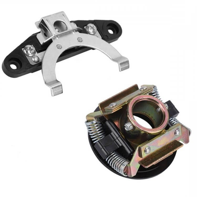
Centrifugal switches are the core components of motor control systems and mainly include two key parts. First, is the centrifugal mechanism, which is directly mounted on the shaft of the motor and moves as the shaft rotates. Second, the switch system is fixed and contains electrical contact devices, which are responsible for controlling the starting coil of the motor.
When the motor starts and begins to accelerate, the centrifugal mass in the centrifugal mechanism will expand outward due to the increase in speed. This outward movement is transmitted to the fixed switch through a series of precise mechanical linkages, triggering its action. In the early stage of motor startup, the centrifugal switch remains closed, which ensures that the starting coil can receive the necessary current. As the motor speed gradually increases, the outward thrust generated by the centrifugal mass also increases. Once the motor reaches the set running speed, this force is enough to push the mechanical linkage, causing the fixed switch to disconnect, thereby disconnecting the current of the starting coil, and the motor enters the normal operating mode.
When the motor stops running, due to the weakening of centrifugal force, the centrifugal block returns to its original position. This process also affects the fixed switch through a mechanical linkage, making it closed and preparing for the next start of the motor. This fallback action ensures that the motor can stop safely and sets the conditions for restarting.
2. Types and Applications of Centrifugal Switches
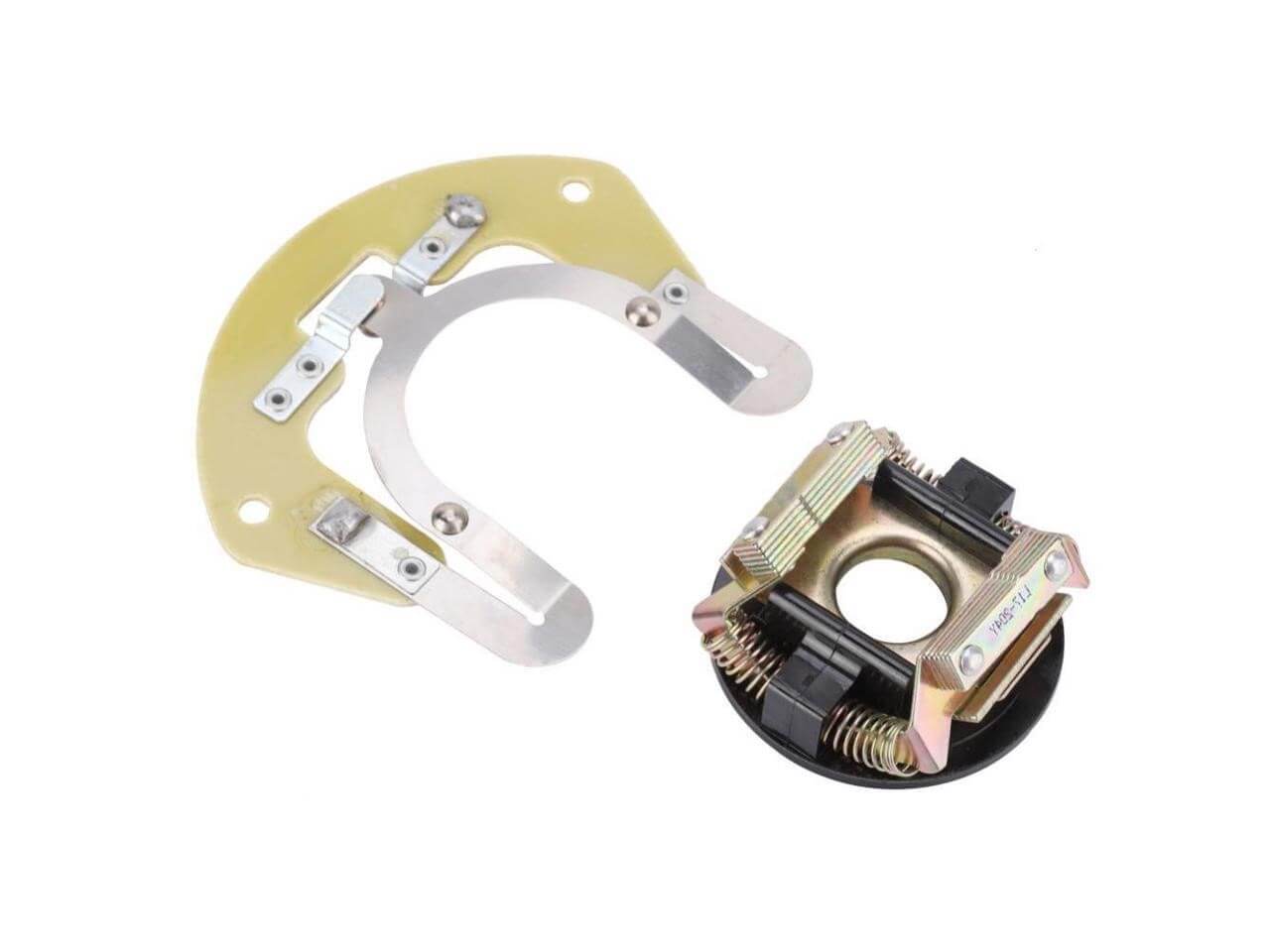
As the core component of the motor control system, centrifugal switches are divided into many types according to their functions and application environments. Each type of centrifugal switch has a specific operating mechanism and applicable scenarios, which enables it to effectively control the start and operation of the motor. The following are several common types of centrifugal switches:
Single capacitor phase shift type without centrifugal switch: This type of switch is widely used in low-power motors, such as electric fans. It uses a capacitor to adjust the phase of the current to help the motor start. This type of switch is widely used in small household appliances because of its simple operation. In actual use, it is necessary to ensure that the capacitor is connected to the circuit when the motor starts and disconnected after the start is completed to avoid unnecessary energy consumption.
Single capacitor phase-shift start centrifugal switch: This switch is commonly found in medium-sized household equipment, such as household fans. It combines a single capacitor and a centrifugal mechanism to ensure that the motor can start smoothly. Although this type of switch is less used in modern applications, it is still the first choice in scenarios that require cost-effectiveness and simple operation. When starting the motor, you need to pay close attention to the sound of the motor and the smoothness of the start to ensure that the centrifugal mechanism can be activated and disconnected at the right time.
Dual capacitor dual-value phase-shift centrifugal switch: This is the most common type of centrifugal switch, especially suitable for motors that require high starting torque, such as air compressors, cutting machines, and bench drills. It is equipped with two capacitors: one for enhancing the starting torque and the other for optimizing the performance during the operation of the motor. The operation of this switch is more complex, and the switching timing of the two capacitors must be precisely controlled to ensure the efficiency of the motor start and operation and its service life.
3. Working Principle of Centrifugal Switches
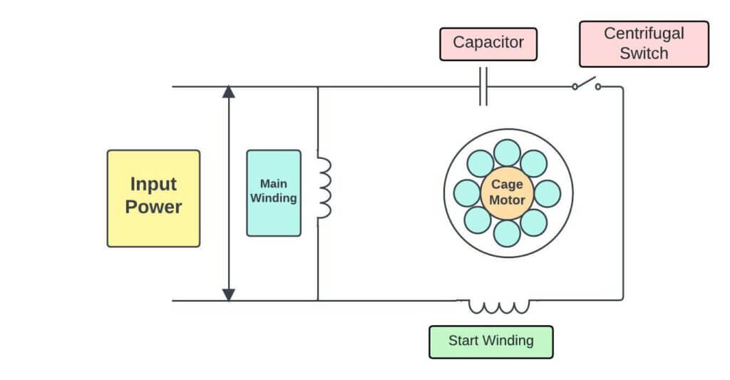
The centrifugal switch uses the rotational power and centrifugal force of a single-phase motor to control the starting circuit. Designed for single-phase motors, this switch is directly mounted on the rotor shaft of the motor and connected in series with the starting circuit. Here are the detailed steps and operation logic of this process:
Motor starting stage: In the initial stage when the motor is powered on and starts to start, the rotor is at rest. At this time, the centrifugal switch remains closed, allowing current to flow through the starting circuit, thereby assisting the motor to start. The operator must ensure that all circuit connections are correct and the circuit is intact at this stage to ensure a smooth flow of current.
Centrifugal force: As the motor speed gradually increases, the centrifugal mechanism begins to feel the effect of centrifugal force. The speed regulator assembly in the centrifugal switch, usually composed of a series of weights or arms, expands outward as the speed increases. This design ensures smooth movement and timely response of the assembly to accurately reflect the changes in motor speed.
Movement of the contact arm and circuit disconnection: When the motor speed reaches the set critical value, the increase in centrifugal force is enough to push the contact arm outward, which causes the centrifugal switch to open. This action disconnects the current in the starting circuit, and the motor transitions to a power supply state that relies solely on its operating circuit. At this critical moment, the operator should closely monitor the speed and operating sound of the motor to ensure that the motor can smoothly transition to normal operation.
Safety and energy consumption considerations: The design of the centrifugal switch not only ensures that the motor can start safely but also effectively reduces energy consumption by disconnecting the circuit in time. If the centrifugal switch fails to disconnect properly during the operation of the motor, it may cause the motor to overload or even damage. Therefore, the operator needs to continuously observe the operation of the motor and the integrity of the circuit to ensure that everything is running normally.
4. The Importance of Centrifugal Switches for Single-phase Motors
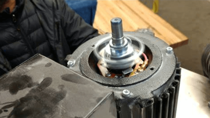
In single-phase motors, not only protect the motor from damage but also ensures that the motor can operate efficiently. This switch remains closed when the motor starts by mechanically controlling the centrifugal force, allowing current to pass through the starting circuit and provide the initial power required for starting. This allows the motor to smoothly transition from a stationary state to a running state, and during this process, it will be obvious that the sound of the motor starting is gradually getting louder and the vibration is gradually increasing.
After the motor starts, once the speed reaches the set value, the centrifugal switch will respond to the centrifugal force, automatically push the contact arm outward, and disconnect the starting circuit. This not only reduces energy consumption but also prevents thermal damage to the starting coil caused by long-term power supply. If the motor is overloaded or overheated, the sensitive response of the centrifugal switch can quickly cut off the main circuit and stop the motor immediately to avoid more serious mechanical or electrical damage.
The centrifugal switch also ensures that the motor operates under ideal electrical conditions, which helps improve the efficiency and output power of the motor. It allows the motor to use the starting coil during the starting phase when additional torque is required and automatically disconnects after reaching a stable operating state, thereby reducing unnecessary power consumption and mechanical wear.
5. Which Motors have Centrifugal Switches?
In the application of single-phase motors, the use of centrifugal switches depends on the starting method of the motor and the specific working requirements. The following are the situations in which various types of motors are equipped with centrifugal switches:
Dual capacitor single-phase motor: This type of motor is usually equipped with a centrifugal switch, which uses a dual capacitor design to provide higher starting torque and improved operating efficiency. In actual operation, you will immediately feel the quick response and strong power when the motor starts, which is mainly due to the role of the starting capacitor. When the motor reaches a stable speed, the centrifugal switch automatically disconnects the starting capacitor to reduce energy consumption, while keeping the running capacitor active and maintaining the efficient operation of the motor.
The capacitor starts a single-phase motor (without a running capacitor): This type of motor relies on capacitors when starting. Once a certain speed is reached, the centrifugal switch disconnects the capacitor and switches to the direct power supply. In operation, the motor starts with a significant initial impulse, followed by a smooth transition to steady-state operation, a change that is noticeable to the operator.
Resistor-started single-phase motors: These motors, equipped with centrifugal switches, use resistors to reduce the starting current and the load on the grid. After starting, the centrifugal switch disconnects the resistors, preventing energy loss and heat damage caused by long-term current passing through the resistors. Operators usually notice that the motor starts gently and the current rises slowly, ensuring a smooth start.
Single-phase deep well pumps: These types of motors are generally not equipped with centrifugal switches because they are designed to run continuously under a steady load and do not require frequent start-stop control. This means that there will be no starting current peaks or capacitor switching during use.
Single-value capacitor single-phase motors: These motors cannot have capacitors removed after starting because the capacitors provide the necessary additional current to maintain the stability of the motor both at start-up and during operation. Removing the capacitors can cause motor power loss and overheating problems. Therefore, maintenance must ensure that the capacitors are connected in good condition to prevent motor performance degradation or failure.
6. Symbol of a Centrifugal Switches for Single-phase Motor
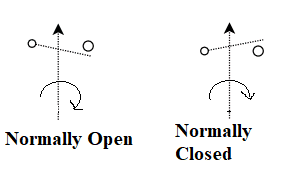
The symbol of the centrifugal switch is a circle with a plus sign in the middle, indicating the closed state of the switch.
The symbol of the centrifugal mechanism is a triangle, indicating the function of the centrifugal mechanism.
7. What is the Purpose of a Centrifugal Switches for the Motor?
Centrifugal switch for motors is widely used in various motors, such as fans, pumps, compressors, etc. In these devices, the centrifugal switch for motors plays an important role in protecting the motor from damage caused by overload or overspeed. In addition, centrifugal switches for motors can also be used to control the start and stop of motors, improving the safety and reliability of equipment.
- Single-phase induction motor: In this type of equipment, a centrifugal switch helps to start the motor smoothly and prevent current shock at start-up, thereby extending the service life of the motor.
- Compressor: In the compressor, the centrifugal switch controls the start of the motor so that it will not accept excessive load before reaching safe speed, which can avoid mechanical failure and energy waste.
- Pump: Pump equipment relies on the centrifugal switch to ensure that the motor starts when the water flow resistance is appropriate, thereby reducing possible mechanical wear and overcurrent problems during the start-up process.
- Fans: In fans, centrifugal switches are used to adjust the starting current to ensure that the motor smoothly transitions to the required operating speed, improving fan efficiency and safety.
- Blowers: Blowers use centrifugal switches to accurately control starting and stopping, ensuring reliable operation even under harsh working conditions, thereby protecting the overall structure of the motor and blower.
- Power tools: In power tools, the role of centrifugal switches is to immediately respond to the operator's start and stop commands, enhancing the operating safety and response speed of the tool.
- Industrial machinery: In complex industrial applications, centrifugal switches ensure that machinery operates under safe and preset parameters, thereby avoiding production interruptions caused by incorrect operation or mechanical failure.
8. Summary
Centrifugal switches are not only an important protection device in single-phase motors, but also a key technology to improve motor efficiency and reliability. Various types of centrifugal switches, such as single-capacitor phase-shifting type, dual-capacitor dual-value phase-shifting type, etc., can enable various motors to perform optimally in different application scenarios. These switches significantly improve the operating efficiency and safety of motors by accurately controlling the switching of starting and running capacitors and automatically disconnecting the circuit after the motor reaches the appropriate speed. Therefore, understanding and applying centrifugal switches is not only related to the performance of the motor but also directly affects the stability and economic benefits of the entire system. In the future design and maintenance of motors, optimizing the design and function of centrifugal switches will be an important direction to improve motor performance.
Frequently Asked Questions [FAQ]
1. What can replace a centrifugal switch?
A centrifugal switch can be replaced by an electronic relay or a solid-state circuit designed to perform the same function of switching the motor's start winding off once it reaches a certain speed. These electronic devices are more reliable in terms of durability and can handle frequent switching better than mechanical switches.
2. Where is the centrifugal switch located?
The centrifugal switch is typically located on the shaft of the motor or integrated into the motor's end bell. For most single-phase motors, this switch is mounted directly on the motor shaft and is actuated by the rotational motion of the shaft itself. It operates in direct relation to the motor’s speed.
3. Can the motor work without the centrifugal switch?
Technically, a motor can run without a centrifugal switch, but it would require manual disconnection of the start winding once the motor reaches operational speed. Without this switch, the start winding would stay engaged, leading to excessive heat buildup and potentially damaging the motor or shortening its lifespan.
4. How can I tell if the centrifugal switch is broken?
To diagnose a faulty centrifugal switch, you can observe a few key symptoms:
The motor fails to start but hums, indicating the start winding is not being disconnected as it should.
The motor starts but doesn't run at full speed or shows signs of overheating, suggesting the switch may be sticking in the closed position.
You can also use a multimeter to test continuity in the switch when the motor is off and at speed. If the continuity does not change from closed to open as the motor speeds up, the switch may be defective.
5. What happens when the centrifugal switch in the motor fails?
If the switch fails to close, the motor will not start as the starting winding necessary for the initial torque is not activated.If it fails to open after the motor reaches operating speed, the start winding will not disengage, causing excessive heat and potential damage to the motor. This prolonged engagement can burn out the start winding and lead to motor failure.
About us
ALLELCO LIMITED
Read more
Quick inquiry
Please send an inquiry, we will respond immediately.
Understanding the Buck Converters: Work Principle, Designing, and Operation
on May 30th
Understanding MOSFET: Types, Working Principles, and Applications
on May 30th
Popular Posts
-

What is GND in the circuit?
on January 1th 2946
-

RJ-45 Connector Guide: RJ-45 Connector Color Codes, Wiring Schemes, R-J45 Applications, RJ-45 Datasheets
on January 1th 2502
-

Fiber Connector Types: SC Vs LC And LC Vs MTP
on January 1th 2091
-

Understanding Power Supply Voltages in Electronics VCC, VDD, VEE, VSS, and GND
on November 9th 1898
-

Comparison Between DB9 and RS232
on January 1th 1765
-

What Is An LR44 Battery?
Electricity, that ubiquitous force, quietly permeates every aspect of our daily lives, from trivial gadgets to life-threatening medical equipment, it plays a silent role. However, truly grasping this energy, especially how to store and efficiently output it, is no easy task. It is against this background that this article will focus on a type of coin cell battery that may seem insignificant on the...on January 1th 1714
-

Understanding the Fundamentals:Inductance Resistance, andCapacitance
In the intricate dance of electrical engineering, a trio of fundamental elements takes center stage: inductance, resistance, and capacitance. Each bears unique traits that dictate the dynamic rhythms of electronic circuits. Here, we embark on a journey to decipher the complexities of these components, to uncover their distinct roles and practical uses within the vast electrical orchestra. Inductan...on January 1th 1662
-

CR2430 Battery Comprehensive Guide: Specifications, Applications and Comparison to CR2032 Batteries
What is CR2430 battery ?Benefits of CR2430 BatteriesNormCR2430 Battery ApplicationsCR2430 EquivalentCR2430 VS CR2032Battery CR2430 SizeWhat to look for when buying the CR2430 and equivalentsData Sheet PDFFrequently Asked Questions Batteries are the heart of small electronic devices. Among the many types available, coin cells play a crucial role, commonly found in calculators, remote controls, and ...on January 1th 1567
-

What Is RF and Why Do We Use It?
Radio Frequency (RF) technology is a key part of modern wireless communication, enabling data transmission over long distances without physical connections. This article delves into the basics of RF, explaining how electromagnetic radiation (EMR) makes RF communication possible. We will explore the principles of EMR, the creation and control of RF signals, and their wide-ranging uses. The article ...on January 1th 1550
-

CR2450 vs CR2032: Can The Battery Be Used Instead?
Lithium manganese batteries do have some similarities with other lithium batteries. High energy density and long service life are the characteristics they have in common. This kind of battery has won the trust and favor of many consumers because of its unique safety. Expensive tech gadgets? Small appliances in our homes? Look around and you'll see them everywhere. Among these many lithium-manganes...on January 1th 1519


