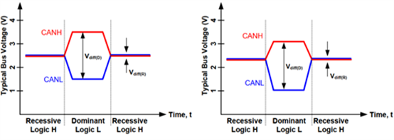
A Deep Dive into Oscilloscopes Simplifying Testing of CAN Bus Networks
Catalog
About us
ALLELCO LIMITED
Read more
Quick inquiry
Please send an inquiry, we will respond immediately.

Simple Formula to Convert Celsius to Fahrenheit
on January 6th

What Are Analog and Digital Signals
on January 5th
Popular Posts
-

What is GND in the circuit?
on January 1th 3036
-

RJ-45 Connector Guide: RJ-45 Connector Color Codes, Wiring Schemes, R-J45 Applications, RJ-45 Datasheets
on January 1th 2606
-

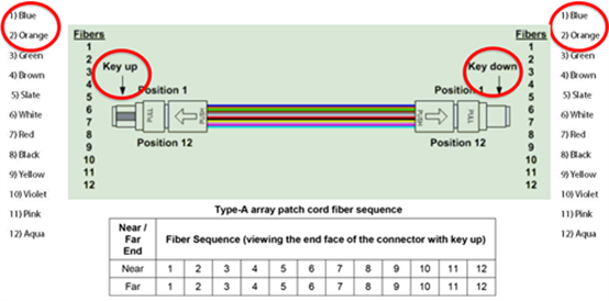
Fiber Connector Types: SC Vs LC And LC Vs MTP
on January 1th 2161
-

Understanding Power Supply Voltages in Electronics VCC, VDD, VEE, VSS, and GND
on November 13th 2064
-

Comparison Between DB9 and RS232
on January 1th 1788
-

What Is An LR44 Battery?
Electricity, that ubiquitous force, quietly permeates every aspect of our daily lives, from trivial gadgets to life-threatening medical equipment, it plays a silent role. However, truly grasping this energy, especially how to store and efficiently output it, is no easy task. It is against this background that this article will focus on a type of coin cell battery that may seem insignificant on the...on January 1th 1754
-

Understanding the Fundamentals:Inductance Resistance, andCapacitance
In the intricate dance of electrical engineering, a trio of fundamental elements takes center stage: inductance, resistance, and capacitance. Each bears unique traits that dictate the dynamic rhythms of electronic circuits. Here, we embark on a journey to decipher the complexities of these components, to uncover their distinct roles and practical uses within the vast electrical orchestra. Inductan...on January 1th 1704
-

CR2430 Battery Comprehensive Guide: Specifications, Applications and Comparison to CR2032 Batteries
What is CR2430 battery ?Benefits of CR2430 BatteriesNormCR2430 Battery ApplicationsCR2430 EquivalentCR2430 VS CR2032Battery CR2430 SizeWhat to look for when buying the CR2430 and equivalentsData Sheet PDFFrequently Asked Questions Batteries are the heart of small electronic devices. Among the many types available, coin cells play a crucial role, commonly found in calculators, remote controls, and ...on January 1th 1640
-

What Is RF and Why Do We Use It?
Radio Frequency (RF) technology is a key part of modern wireless communication, enabling data transmission over long distances without physical connections. This article delves into the basics of RF, explaining how electromagnetic radiation (EMR) makes RF communication possible. We will explore the principles of EMR, the creation and control of RF signals, and their wide-ranging uses. The article ...on January 1th 1618
-

Comprehensive guide to hFE in transistors
Transistors are crucial components in modern electronic devices, enabling signal amplification and control. This article delves into the knowledge surrounding hFE, including how to select a transistor's hFE value, how to find hFE, and the gain of different types of transistors. Through our exploration of hFE, we gain a deeper understanding of how transistors work and their role in electronic circu...on November 13th 1561
HOT Part Number
-
HFBR-2526ETZ
Broadcom Limited
FIBER OPTIC RCVR 1.67V VERSATILE
XMR-03V
JST Sales America Inc.
CONN HOUSING 3 POS 2.5MM
74AC251SJX
onsemi
IC MULTIPLEXER 1 X 8:1 16SOP
BZX84B30Q-7-F
Diodes Incorporated
TIGHT TOLERANCE ZENER SOT23 T&R
MAX253EUA+
Analog Devices Inc./Maxim Integrated
IC DRVR TRANSFORMER 1W 8UMAX
12063C474MAT4A
KYOCERA AVX
CAP CER 0.47UF 25V X7R 1206
RN5VD14AA-TR-FE
Nisshinbo Micro Devices Inc.
IC SUPERVISOR 1 CHANNEL SOT23-5
PD15-22C/TR8
Everlight Electronics Co Ltd
SENSOR PHOTODIODE 940NM 4SMD
S29GL512T10FHI010
Infineon Technologies
IC FLASH 512MBIT PARALLEL 64FBGA
M74HC373RM13TR
STMicroelectronics
IC LATCH OCTAL D-TYPE 20-SOIC
IL715ETR13
NVE Corporation
DGTL ISO 2.5KV GEN PURP 16SOIC
XC95288XL-7FG256I
AMD
IC CPLD 288MC 7.5NS 256FBGA
TPS57160ZQDGQRQ1
Texas Instruments
IC REG BUCK ADJ 1.5A 10MSOP
REG101NA-2.5/3K
Texas Instruments
IC REG LINEAR 2.5V 100MA SOT23-5
EKMC1603111
Panasonic Electric Works
SENSOR MOTION PIR 12M RANGE WHT
5AGXBB7D4F35I5G
Intel
IC FPGA 544 I/O 1152FBGA
SMC3K43CA-M3/57
Vishay General Semiconductor - Diodes Division
TVS DIODE 43VWM 69.4VC DO214AB
NRVBB60H100CTT4G
onsemi
DIODE SCHOTTKY 100V 30A D2PAK-3 -
74F244SC
onsemi
IC BUF NON-INVERT 5.5V 20SOIC
BD00HA3MEFJ-ME2
Rohm Semiconductor
IC REG LIN POS ADJ 300MA 8HTSOP
XC68C812A4PV5
Freescale Semiconductor
16-BIT, EEPROM, 5MHZ, HCMOS
MAL215252229E3
Vishay Beyschlag/Draloric/BC Components
CAP ALUM 22UF 20% 200V RADIAL
GRM1555C2A8R4DA01D
Murata Electronics
CAP CER 8.4PF 100V C0G/NP0 0402
LT6005IGN#TRPBF
Analog Devices Inc.
IC OPAMP GP 4 CIRCUIT 16SSOP
TPS61163YFFR
Texas Instruments
IC LED DRV RGLTR PWM 30MA 9DSBGA
SMAJ54A
Taiwan Semiconductor Corporation
TVS DIODE 54VWM 87.1VC DO214AC
PMN70EPEX
Nexperia USA Inc.
MOSFET P-CH 30V 4.4A 6TSOP
MC9S12C32VFUE16
NXP USA Inc.
IC MCU 16BIT 32KB FLASH 80QFP
AXT530124
Panasonic Electric Works
CONN SOCKET 30POS SMD GOLD
STGP30H60DF
STMicroelectronics
IGBT 600V 60A 260W TO220
XCV400-4FG676C
AMD
IC FPGA 404 I/O 676FCBGA
F930G336MAA
KYOCERA AVX
CAP TANT 33UF 20% 4V 1206
0326015.MXP
Littelfuse Inc.
FUSE CERM 15A 250VAC 60VDC 3AB
MLG1608B3N9ST000
TDK Corporation
FIXED IND 3.9NH 600MA 140MOHM SM
PE-65499NL
Pulse Electronics
XFRMR ISDN S-INTERFACE 1:2 T/H
OPA2373AIDGSR
Texas Instruments
IC CMOS 2 CIRCUIT 10VSSOP -

GS1531-CBE2
Semtech Corporation
IC VIDEO SERIALIZER 100BGA
10SVP56M
Panasonic Electronic Components
CAP ALUM POLY 56UF 20% 10V SMD
SLF7045T-680MR60-PF
TDK Corporation
FIXED IND 68UH 770MA 210MOHM SMD
LT1672IS8#TRPBF
Analog Devices Inc.
IC OPAMP GP 1 CIRCUIT 8SO
FWX-350A
Eaton - Bussmann Electrical Division
FUSE CARTRIDGE 350A 250VAC/VDC
HUFA76645S3S
Fairchild Semiconductor
MOSFET N-CH 100V 75A D2PAK
2SC5536A-TL-H
onsemi
RF TRANS NPN 12V 1.7GHZ 3SSFP
GCM1885C2A3R7CA16D
Murata Electronics
CAP CER 3.7PF 100V C0G/NP0 0603
ELT3043
Everlight Electronics Co Ltd
OPTOISOLATOR 5KV TRIAC 4DIP
LTC2460IMS#TRPBF
Analog Devices Inc.
IC ADC 16BIT SIGMA-DELTA 12MSOP
2225HC822KAZ1A
KYOCERA AVX
CAP CER 8200PF 3KV X7R 2225
PD20010-E
STMicroelectronics
TRANS RF N-CH FET POWERSO-10RF
AP2125KS-2.8TRG1
Diodes Incorporated
IC REG LINEAR 2.8V 300MA SC70-5
75K62100S66BX
Broadcom Limited
9M TERNARY IP-COPROCESSOR
MP6219DN-LF-Z
Monolithic Power Systems Inc.
IC PWR SWITCH N-CHAN 1:1 8SOIC
MAX9032AKA+T
Analog Devices Inc./Maxim Integrated
IC COMPARATOR 2 GEN PUR SOT23-8
TMS320DM6437ZWTQ4
Texas Instruments
IC DGTL MEDIA PROCESSOR 361-BGA
CY62137VNLL-70ZSXET
Infineon Technologies
IC SRAM 2MBIT PARALLEL 44TSOP II