A Comprehensive Guide to Rectifier Diodes: Structure, Working Mechanism, and Maintenance
Rectifier diodes are pivotal components in electronic circuits, performing the crucial task of converting alternating current (AC) to direct current (DC). Their operation hinges on a specialized semiconductor structure known as the PN junction, comprising a P-type semiconductor, rich in holes, and an N-type semiconductor, abundant in electrons. The fundamental principle behind their functionality is their ability to allow current flow in a single direction—from the anode to the cathode—thereby rectifying AC into DC. Understanding the nuances of their structure, such as the effects of forward and reverse bias conditions, is essential for optimizing their use in various applications, ranging from power supplies to signal modulation. The intricate balance between the applied external voltage and the internal barrier potential of the PN junction dictates the diode's conducting and blocking states. This dynamic interaction not only facilitates efficient power conversion but also plays a critical role in protecting circuits from reverse currents and voltage spikes.Catalog
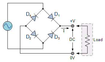
Figure 1: Full Wave Rectifier Diode
Basic Structure of Rectifier Diodes
Rectifier diodes are essential semiconductor devices in electronic circuits, converting alternating current (AC) to direct current (DC). Their core function relies on their ability to conduct current in only one direction, from the anode to the cathode. This is achieved through a special semiconductor structure known as the PN junction, composed of a P-type semiconductor rich in holes and an N-type semiconductor rich in electrons.
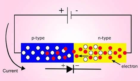
Figure 2: Diodes Internal Diagram
When a voltage is applied across a rectifier diode, the relationship between the external voltage and the barrier potential of the PN junction is crucial. In a forward-biased condition, where the P-side is at a higher potential than the N-side, the built-in barrier of the PN junction decreases. This allows current to flow from the P-side to the N-side, and the diode is said to be conducting. In this state, the voltage drop is typically around 0.7V for silicon diodes and about 0.3V for germanium diodes. This voltage drop is influenced by the material properties and the design of the diode.
Conversely, in a reverse-biased condition, where the N-side is at a higher potential than the P-side, the barrier height increases, preventing current flow. The diode is then blocked. While ideally, no current flows, in reality, a small leakage current exists but is usually negligible. However, if the reverse voltage exceeds a certain threshold known as the breakdown voltage, the diode will suddenly conduct a large current. This phenomenon, called reverse breakdown, occurs because the strong electric field within the semiconductor imparts sufficient energy to electrons, breaking covalent bonds and resulting in a surge of current.
These characteristics of rectifier diodes not only affect power conversion but also have an impact on circuit protection and signal modulation. In power supplies, they prevent potential reverse currents that could damage the power source or other components. Their basic properties enable their use in modulators, demodulators, wireless transmitters, receivers, and various other electronic devices.
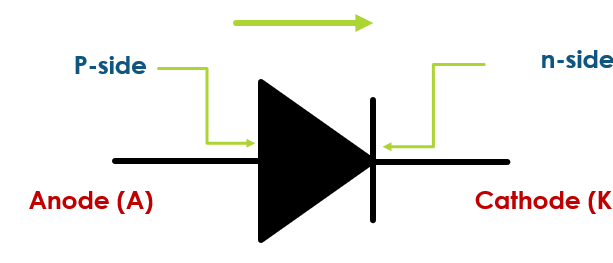
Figure 3: Symbol of Diode
Specific Parameters of Rectifier Diodes
The performance and applicability of rectifier diodes in electronic circuit design are affected by various technical parameters.
Maximum Average Rectified Current (IF)
This parameter indicates the maximum current a diode can continuously handle in the forward-biased condition. Matching the actual operating current to this parameter helps prevent overheating or damage. When selecting a diode, consider the expected current flow to ensure durability and reliability.
Maximum Reverse Working Voltage (VR)
This is the highest voltage a diode can safely withstand in the reverse-biased condition. It’s important to choose a diode with a VR higher than the maximum voltage that might occur in the circuit to avoid unintended breakdown. Ensuring this match protects the circuit from potential damage under abnormal conditions.
Breakdown Voltage (VB)
The breakdown voltage defines the limit at which a diode loses its ability to block current in the reverse direction, leading to a sudden surge of current. Selecting a diode with an appropriate VB ensures it can handle voltage spikes without causing catastrophic failures.
Maximum Operating Frequency (FM)
This parameter reflects how well a diode performs at various frequencies. Due to the inherent capacitance of the PN junction, diodes have limitations in handling high-frequency signals. In high-frequency applications, the junction capacitance can cause response delays, affecting rectification efficiency and signal integrity.
Reverse Recovery Time
The reverse recovery time is the time it takes for a diode to switch from conducting (forward-biased) to blocking (reverse-biased). This is particularly important in fast-switching circuits like switch-mode power supplies and frequency converters. A shorter recovery time reduces efficiency losses and thermal buildup, enhancing overall circuit performance and reliability.
Zero Bias Capacitance (Junction Capacitance)
This is the inherent capacitance across the PN junction when no external voltage is applied. It impacts the diode’s performance in high-frequency applications, especially in analog signal processing. Diodes with lower junction capacitance are preferred for high signal fidelity, as higher capacitance can cause signal distortion.
When working with rectifier diodes, the following steps and detailed observations can enhance practical understanding:
Evaluating IF and VR: Measure the actual current and voltage in your circuit. Select a diode with IF and VR ratings comfortably above these measurements to ensure reliability.
Assessing VB: Consider voltage spikes in your circuit. Choose a diode with a breakdown voltage higher than any possible transient voltages to protect against unexpected surges.
Determining FM and Junction Capacitance: For high-frequency applications, test the diode’s response. Ensure the diode can handle the required frequency without significant performance degradation.
Testing Reverse Recovery Time: In fast-switching circuits, observe the diode’s transition from conducting to blocking. Opt for diodes with shorter reverse recovery times to minimize efficiency loss and heat generation.
By carefully considering these parameters and following a logical sequence in testing and selection, one can ensure the chosen rectifier diode meets the specific needs of the electronic circuit, enhancing performance and longevity.
|
Rectifier diode name |
Peak
reverse |
Max. forward |
Peak surge |
Max
voltage |
|
1N4001 diode |
50 |
1 A |
30 A |
1.1 |
|
1N4002 diode |
100 |
1 A |
30 A |
1.1 |
|
1N4003 diode |
200 |
1 A |
30 A |
1.1 |
|
1N4004 diode |
400 |
1 A |
30 A |
1.1 |
|
1N4007 diode |
1000 |
1 A |
30 A |
1.1 |
|
1N5402 diode |
200 |
3 A |
200 A |
1.2 |
|
1N5406 diode |
600 |
3 A |
200 A |
1.2 |
|
1N5408 diode |
1000 |
3 A |
200 A |
1.2 |
Chart 1: The Most Common Rectifier Diodes and Their Characteristics
Working Mechanism of Rectifier Diodes
The working mechanism of rectifier diodes is fundamental to their crucial role in electronic circuit design. These devices operate by allowing current to flow in only one direction, enabling the conversion of AC to DC.
Forward Bias Condition
When a positive voltage is applied to the anode relative to the cathode, the PN junction barrier decreases. Electrons move from the N-type to the P-type semiconductor, while holes move from the P-type to the N-type. This movement allows current to flow, making the diode act like a closed switch.
Reverse Bias Condition
When a positive voltage is applied to the cathode relative to the anode, the PN junction barrier increases. This prevents charge carriers from crossing the junction, stopping current flow. The diode behaves like an open switch. Only a minimal leakage current flows unless the reverse voltage exceeds the breakdown voltage, at which point significant current can flow, potentially damaging the circuit.
The practical Operation is as follows:
Firstly, connect a rectifier diode in series with an LED and apply a voltage. Then, apply a positive voltage to the anode. The diode conducts, allowing current through the LED, causing it to light up. This demonstrates the diode’s ability to conduct in one direction. Next, apply a positive voltage to the cathode. The LED remains off, showing the diode blocks current in this direction, protecting the circuit from reverse voltage.
Rectifier diodes are used for voltage rectification, circuit protection, signal modulation, and as switching elements in various devices such as modulators, demodulators, and driver circuits. Their ability to control and direct current flow ensures optimal performance and reliability of electronic devices.
Advantages and Disadvantages of Rectifier Diodes
Advantages of Rectifiers
Versatility and Utility: Rectifiers are used in numerous applications, from consumer electronics to large-scale industrial processes. They ensure a stable power supply, critical for the functioning of various devices.
High Efficiency: Modern rectifiers use advanced semiconductor materials like silicon carbide (SiC) and gallium nitride (GaN). These materials offer higher thermal stability and electrical efficiency. Improved materials reduce energy loss during conversion, enhancing overall system efficiency.
Enhanced Reliability: With superior materials, rectifiers can manage higher voltages and currents more reliably. Better heat dissipation properties minimize the risk of overheating.
Smart Control: Modern rectifiers often incorporate intelligent control systems to optimize power management. These systems can automatically adjust output voltage and current to meet the varying needs of different devices, improving energy efficiency and operational flexibility.
Disadvantages of Rectifiers
Impact on Power Quality: During rectification, nonlinear loads can distort current waveforms, creating harmonics—extra frequencies above the fundamental frequency. However, harmonics can degrade the quality of the power supply and potentially harm other equipment connected to the grid.
Interference: Electrical noise is common in electronic systems, interfering with the normal operation of devices. Additional filters and power quality control technologies are often required to reduce these adverse effects.
To address these challenges, rectifier technology continues to evolve:
Material Innovations: These advanced materials, such as SiC and GaN, increase efficiency and performance, allowing rectifiers to handle higher voltages and currents while reducing energy losses.
Enhance Heat Management: Enhanced thermal stability reduces heat generation, ensuring reliable operation under high-stress conditions.
Optimized Power Management: Modern designs incorporate smart control technologies to automatically adjust power output, optimizing energy use and improving adaptability to different operational demands.
Despite challenges like electrical noise and harmonics, ongoing innovations in rectifier technology are continually improving their performance. The use of advanced materials and smart technologies ensures rectifiers remain indispensable in enhancing energy efficiency and reducing operational costs. These developments highlight the progress in electronics and the growing demand for efficient and reliable power solutions. Rectifiers will continue to be a cornerstone in future power systems and electronic devices, reflecting their critical role in modern technology.
What is the Function of a Rectifier Diode?
The rectifier’s diode is typically made from semiconductor materials such as germanium or silicon and forms an effective PN junction to perform its core function. Let's take an in-depth study of the working mechanism and main characteristics of rectifier diodes.
Forward Characteristics
The forward characteristics of a rectifier diode are central to its function. When a forward voltage is initially applied, it is usually insufficient to overcome the electric field within the PN junction. At this stage, the current is nearly zero, known as the "threshold voltage." Only when the forward voltage exceeds this threshold does the diode start to conduct. As the voltage increases further, the current rises rapidly, while the diode's terminal voltage remains relatively constant, demonstrating excellent conductivity. Applying a small forward voltage does not produce a significant current. Once the forward voltage surpasses the threshold, the diode begins to conduct. As voltage increases, current increases sharply. The terminal voltage remains stable even as the current rises, showing good conductivity.
Reverse Characteristics
The behavior of a rectifier diode under reverse bias is markedly different. In this state, if the applied reverse voltage does not exceed a specific threshold, the diode exhibits a very low reverse current, mainly due to minority carrier drift. The reverse saturation current is significantly influenced by temperature. Silicon diodes generally have a much lower reverse current than germanium diodes. As temperature rises, the number of minority carriers in the semiconductor material increases, leading to a higher reverse current. Applying a reverse voltage does not produce significant current unless a threshold is exceeded. Low reverse current is primarily due to this phenomenon. Higher temperatures increase the number of minority carriers, raising the reverse current. Silicon diodes have lower reverse currents compared to germanium diodes.
Reverse Breakdown
Reverse breakdown is a crucial electrical characteristic of rectifier diodes, occurring in two types: Zener breakdown and avalanche breakdown.
Zener Breakdown: This typically occurs in highly doped semiconductors with a narrow depletion region. A lower reverse voltage can break the covalent bonds, generating electron-hole pairs.
This phenomenon is governed by quantum mechanics.
Avalanche Breakdown: This happens at higher reverse voltages where the external electric field is strong enough to accelerate valence electrons. These electrons gain sufficient energy to break covalent bonds through collision, creating many electron-hole pairs. This results in a significant gain in electrons.
In both types, the process involves a significant increase in current once the breakdown voltage is reached, and it’s essential to control these effects to prevent damage to the diode and the circuit in which it is used.
Rectifier Circuits
Half-Wave Rectifier
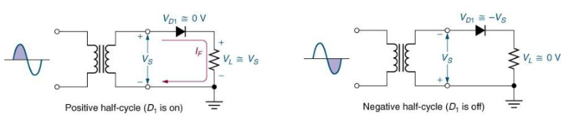
Figure 4: Half-Wave Rectifier Circuit
A half-wave rectifier is one of the simplest ways to achieve this conversion. The key component is a rectifier diode. When AC power is applied to the half-wave rectifier, the diode is forward-biased during the positive half-cycle, allowing current to pass through. During the negative half-cycle, the diode is reverse-biased, blocking the current. As a result, the output is a pulsating DC voltage that corresponds only to the positive half-cycle of the AC input. Although simple and low-cost, the main drawback of a half-wave rectifier is its inefficiency, as it doesn't utilize the negative half-cycle, leading to wasted energy.
The setup of the half-wave rectifier circuit is as follows:
• The rectifier diode is placed in series with the load. The diode conducts, allowing current to pass through.
• The diode blocks the current, preventing flow.
• Pulsating DC voltage corresponding to the positive AC cycle.
Full-Wave Rectifier
A full-wave rectifier offers a more efficient solution. Using a "diode bridge" composed of four diodes, it converts both halves of the AC cycle to a positive output. During the positive half-cycle, diodes D1 and D2 conduct, directing current through the load to the output. During the negative half-cycle, diodes D3 and D4 conduct, maintaining the same current direction through the load. This configuration effectively uses the entire AC cycle, improving energy utilization and providing a more stable DC output.
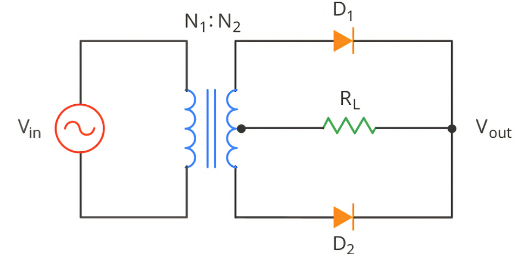
Figure 5: Full-Wave Rectifier Circuit
The full wave rectifier circuit is set up as follows:
• Four diodes are arranged to form a bridge.
• Diodes D1 and D2 conduct, current flows through the load.
• Diodes D3 and D4 conduct, current direction remains consistent.
• DC voltage utilizing both halves of the AC input.
Bridge Rectifier
The bridge rectifier circuit further enhances the full-wave rectifier, suitable for more complex and demanding applications. It includes a transformer and a main rectifier bridge to manage voltage and current more effectively. During the positive half-cycle, current flows to point A, where diode 2 conducts due to the higher voltage, directing current through the load to the output. In the negative half-cycle, despite the reversed current direction, the special configuration of diodes ensures the output current direction remains consistent. This design not only ensures continuous and stable current output but also improves overall efficiency and output quality. Bridge rectifiers excel in high-efficiency and high-stability applications like electric vehicle charging stations and large industrial power supplies.
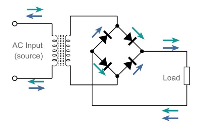
Figure 6: Bridge Rectifier Circuit
The bridge rectifier circuit is set up as follows:
• Adjusts the voltage to suitable levels for rectification.
• Current flows through diode 2, maintaining output direction.
• Diode configuration keeps output current direction stable.
• Continuous and stable DC voltage, improved efficiency and quality.
These rectifier designs ensure reliable DC power conversion, supporting the stable operation of electronic devices and high-demand applications.
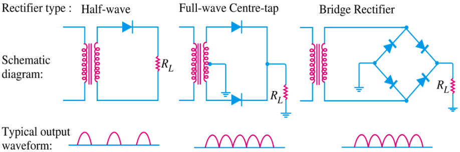
Figure 7: Comparison of Rectifier Diode circuit diagrams
Causes and Prevention Measures of Rectifier Diode Failure
Overvoltage
Overvoltage is a primary cause of rectifier diode failure. When the voltage in a circuit suddenly exceeds the diode's maximum voltage capacity, it can lead to reverse breakdown and permanent damage. Overvoltage typically occurs due to power supply issues, lightning strikes, or electrical grid fluctuations. To prevent this, incorporate appropriate overvoltage protection components like clamp diodes or metal oxide varistors (MOVs) into the circuit. These components quickly absorb excess voltage when it surpasses a safe threshold, protecting the diode from damage.
Overcurrent
Overcurrent is another common cause of rectifier diode damage. When the current passing through the diode exceeds its maximum rated current, it can cause overheating, accelerating internal structural degradation and potentially leading to failure. Design the circuit to ensure current ratings are within safe limits and account for peak currents that might occur during operation. Using current limiters or fuses can effectively prevent overcurrent issues.
Environmental Factors
Environmental conditions also significantly impact the stability and lifespan of rectifier diodes. High temperatures, humidity, or chemically corrosive environments can accelerate the aging process of the diodes. When designing and installing diodes, choose models suitable for the specific operating environment and ensure proper temperature control and protective measures.
Electrical Noise and High-Frequency Oscillations
Electrical noise and high-frequency oscillations can negatively affect rectifier diodes. In high-frequency applications, frequent switching and rapid current changes can damage diodes. For these applications, select rectifier diodes designed for high-frequency use or implement alternative circuit designs to mitigate these issues.
To ensure the reliability and extend the lifespan of rectifier diodes, it is essential to consider multiple factors such as proper design, suitable protection measures, adherence to operating conditions, and appropriate installation environments. By implementing these preventive strategies, you can effectively avoid diode damage and ensure the stable operation of electronic devices.
Maintenance and Inspection of Rectifier Diodes
Ensuring the long-term stability and maximizing the lifespan of rectifier diodes requires regular maintenance and inspection. These methods identify potential issues early and ensure the diodes operate efficiently within electronic devices.
Regular Electrical Testing
Regular checks involve detailed evaluations of the diode's electrical characteristics, primarily by measuring its forward and reverse resistance. Use a digital or analog multimeter for these measurements. The diode test function on the multimeter can conveniently check the forward voltage drop and reverse leakage current. In forward bias mode, a healthy diode should show a characteristic forward voltage drop, usually between 0.6 and 0.7 volts. In reverse bias mode, a good diode should display a high resistance value or indicate an "open" circuit on the digital multimeter.
Visual Inspection
Visual inspection is also a crucial part of maintenance. Look for any visible signs of damage on the diode and its mounting points, such as cracks, discoloration, or burn marks. Ensure that solder joints are secure and check for any signs of loosening or corrosion.
Thermal Imaging
Thermal imaging tests can further ensure the proper functioning of the diodes. By monitoring the heat distribution under normal operating conditions, you can detect any uneven thermal patterns, which might indicate internal defects or overloading. This non-contact method is especially useful for high-risk or critical applications.
Comprehensive Assessment
Combining electrical testing, visual inspection, and thermal imaging provides a thorough assessment of the rectifier diode's health. If any anomalies are detected, take immediate action to repair or replace the diode to prevent circuit failure or device damage.
By consistently performing these maintenance and inspection tasks, you can significantly improve the reliability of rectifier diodes, ensuring the stability and safety of the entire electronic system.
Conclusion
Ensuring the optimal performance and longevity of rectifier diodes necessitates a comprehensive approach that combines careful selection based on specific technical parameters with diligent maintenance and inspection routines. Key parameters such as maximum average rectified current (IF), maximum reverse working voltage (VR), breakdown voltage (VB), maximum operating frequency (FM), reverse recovery time, and zero bias capacitance must be meticulously evaluated to match the diode to its intended application. Regular electrical testing, visual inspection, and thermal imaging are essential practices to detect potential issues early. By integrating these preventive measures, one can significantly reduce the risk of diode failure, thereby ensuring the stable and efficient operation of electronic devices. The ongoing advancements in semiconductor materials and design methodologies continue to enhance the performance capabilities of rectifier diodes, making them indispensable in the ever-evolving landscape of modern electronics.
Frequently Asked Questions [FAQ]
1. What are rectifier diodes used for?
Rectifier diodes are used to convert alternating current (AC) into direct current (DC). In addition to this, rectifier diodes are used in various applications, including signal demodulation, voltage regulation, and circuit protection by blocking reverse current to safeguard other components.
2. What is the purpose of a rectifier?
The primary purpose of a rectifier is to convert AC, which periodically reverses direction, into DC, which flows in a single direction. This conversion is crucial for powering electronic devices that require a steady DC supply. Rectifiers are also used in power supplies, radio signal detection, and the elimination of AC noise in DC signals, thereby ensuring the proper functioning of electronic circuits.
3. Which rectifier is mostly used and why?
The full-wave bridge rectifier is the most commonly used type because it efficiently converts both halves of the AC cycle into a consistent DC output. This design utilizes four diodes arranged in a bridge configuration, allowing for full utilization of the input AC signal and providing a smoother DC output with less ripple compared to a half-wave rectifier. Its efficiency, reliability, and ability to handle higher loads make it the preferred choice in most power supply applications.
4. How to test a rectifier?
To test a rectifier, follow these steps:
Turn Off Power: Ensure the circuit is powered off and discharged.
Use a Multimeter: Set the multimeter to the diode testing mode.
Test Forward Bias: Place the positive probe on the anode and the negative probe on the cathode of the diode. A typical forward voltage drop (usually around 0.6 to 0.7 volts for silicon diodes) should be displayed.
Test Reverse Bias: Reverse the probes, placing the positive probe on the cathode and the negative probe on the anode. The multimeter should display a high resistance or an "open" circuit, indicating no current flow in reverse bias.
Visual and Thermal Inspection: Check for physical damage or discoloration, and use thermal imaging if necessary to identify overheating issues.
5. How do you read a diode?
Identify Terminals: Locate the anode and cathode of the diode. The cathode is usually marked with a stripe.
Set Multimeter: Switch the multimeter to diode testing mode.
Test Forward Bias: Connect the red (positive) probe to the anode and the black (negative) probe to the cathode. The multimeter should display the forward voltage drop, typically between 0.6 and 0.7 volts for silicon diodes.
Test Reverse Bias: Reverse the probes, connecting the red probe to the cathode and the black probe to the anode. The multimeter should show a high resistance or an "open" circuit, indicating no significant current flow in the reverse direction.
About us
ALLELCO LIMITED
Read more
Quick inquiry
Please send an inquiry, we will respond immediately.
Stepper Motor Wire Guide - Color Codes, Wiring Methods
on May 23th
Pigtail Connectors Guide - Definition, Operating Principles and Construction, Types
on May 21th
Popular Posts
-

What is GND in the circuit?
on January 1th 2937
-

RJ-45 Connector Guide: RJ-45 Connector Color Codes, Wiring Schemes, R-J45 Applications, RJ-45 Datasheets
on January 1th 2498
-

Fiber Connector Types: SC Vs LC And LC Vs MTP
on January 1th 2088
-

Understanding Power Supply Voltages in Electronics VCC, VDD, VEE, VSS, and GND
on November 9th 1888
-

Comparison Between DB9 and RS232
on January 1th 1759
-

What Is An LR44 Battery?
Electricity, that ubiquitous force, quietly permeates every aspect of our daily lives, from trivial gadgets to life-threatening medical equipment, it plays a silent role. However, truly grasping this energy, especially how to store and efficiently output it, is no easy task. It is against this background that this article will focus on a type of coin cell battery that may seem insignificant on the...on January 1th 1712
-

Understanding the Fundamentals:Inductance Resistance, andCapacitance
In the intricate dance of electrical engineering, a trio of fundamental elements takes center stage: inductance, resistance, and capacitance. Each bears unique traits that dictate the dynamic rhythms of electronic circuits. Here, we embark on a journey to decipher the complexities of these components, to uncover their distinct roles and practical uses within the vast electrical orchestra. Inductan...on January 1th 1651
-

CR2430 Battery Comprehensive Guide: Specifications, Applications and Comparison to CR2032 Batteries
What is CR2430 battery ?Benefits of CR2430 BatteriesNormCR2430 Battery ApplicationsCR2430 EquivalentCR2430 VS CR2032Battery CR2430 SizeWhat to look for when buying the CR2430 and equivalentsData Sheet PDFFrequently Asked Questions Batteries are the heart of small electronic devices. Among the many types available, coin cells play a crucial role, commonly found in calculators, remote controls, and ...on January 1th 1541
-

What Is RF and Why Do We Use It?
Radio Frequency (RF) technology is a key part of modern wireless communication, enabling data transmission over long distances without physical connections. This article delves into the basics of RF, explaining how electromagnetic radiation (EMR) makes RF communication possible. We will explore the principles of EMR, the creation and control of RF signals, and their wide-ranging uses. The article ...on January 1th 1537
-

CR2450 vs CR2032: Can The Battery Be Used Instead?
Lithium manganese batteries do have some similarities with other lithium batteries. High energy density and long service life are the characteristics they have in common. This kind of battery has won the trust and favor of many consumers because of its unique safety. Expensive tech gadgets? Small appliances in our homes? Look around and you'll see them everywhere. Among these many lithium-manganes...on January 1th 1504
HOT Part Number
-

AD8107ASTZ
Analog Devices Inc.
IC CROSSPOINT SWITCH 16X5 80LQFP
KSD880Y
onsemi
TRANS NPN 60V 3A TO220-3
VI-J03-09
Vicor Corporation
VI-J03-09 24V/24V 55W SMD
K4F8E304HB-MGCJ
Samsung Semiconductor, Inc.
LPDDR4 8Gb x32 3733 Mbps 1.1v 20
SN74HC241PWR
Texas Instruments
IC BUFFER NON-INVERT 6V 20TSSOP
ATSAMD20E17A-AU
Microchip Technology
IC MCU 32BIT 128KB FLASH 32TQFP
0805YC471JAT2A
KYOCERA AVX
CAP CER 470PF 16V X7R 0805
4300H5LC
Visual Communications Company - VCC
LED GREEN DIFFUSED T-1 3/4 T/H
VLA541-11R
Powerex Inc.
IC GATE DRVR PWR MGMT MOSFET
1N4756A-TAP
Vishay General Semiconductor - Diodes Division
DIODE ZENER 47V 1.3W DO41
12061A471MAT2A
KYOCERA AVX
CAP CER 470PF 100V NP0 1206
MM74HC4052SJX
Fairchild Semiconductor
IC SWITCH SP4T X 2 100OHM 16SOP
74ACT11244DWR
Texas Instruments
IC BUF NON-INVERT 5.5V 24SOIC
1N3261
Microchip Technology
STANDARD RECTIFIER
IXBOD1-28RD
IXYS
TVS DEVICE MIXED 2800V BOD
0201YC681KAT2A
KYOCERA AVX
CAP CER 680PF 16V X7R 0201
08055A2R2CAT2M
KYOCERA AVX
CAP CER 2.2PF 50V NP0 0805
CX2520DB16000D0GEJCC
KYOCERA AVX
CRYSTAL 16.0000MHZ 8PF SMD -
MAX136CMH
Analog Devices Inc./Maxim Integrated
LOW POWER, 3 1/2 DIGIT ADC
NC7SP17L6X
onsemi
IC BUF NON-INVERT 3.6V 6MICROPAK
TSB41AB1PHP
Texas Instruments
IC TRANSCEIVER HALF 2/2 48HTQFP
P0544NLT
Pulse Electronics
PULSE XFMR 1:1:1 3.3MH
USB260-E3/52T
Vishay General Semiconductor - Diodes Division
DIODE GEN PURP 600V 2A DO214AA
HMC998APM5E
Analog Devices Inc.
IC RF AMP GPS 0HZ-22GHZ 32LFCSP
TLV70433DBVR
Texas Instruments
IC REG LINEAR 3.3V 150MA SOT23-5
ADR423BRZ
Analog Devices Inc.
IC VREF SERIES 0.04% 8SOIC
ISL84514IBZ
Intersil
IC SWITCH SPST-NOX1 20OHM 8SOIC
P1016NSE5DFB
NXP USA Inc.
IC MPU Q OR IQ 667MHZ 561TEBGA1
DS90CP22M-8
Texas Instruments
IC CROSSPOINT SW 1 X 2:2 16SOIC
RB530VM-30TE-17
Rohm Semiconductor
DIODE SCHOTTKY 30V 100MA UMD2
AD9914BCPZ
Analog Devices Inc.
IC DDS 12BIT 88LFCSP
EXB30-48D05-3V3
Artesyn Embedded Power
DC DC CONVERTER 5V 3.3V 30W
GRM0225C1E7R0CA03L
Murata Electronics
CAP CER 7PF 25V C0G/NP0 01005
J0011D21NL
Pulse Electronics
CONN JACK 1PORT 100 BASE-TX PCB
SI1003-C-GM
Silicon Labs
IC RF TXRX+MCU ISM<1GHZ 42WFQFN
BD236STU
onsemi
TRANS PNP 60V 2A TO126-3 -

V24A36T400BG3
Vicor Corporation
DC DC CONVERTER 36V 400W
1808HA330MAT1A
KYOCERA AVX
CAP CER 33PF 3KV NP0 1808
MC74AC138D
onsemi
IC DECODER/DEMUX 1:8 16-SOIC
NJM78L05UA-TE1
Nisshinbo Micro Devices Inc.
IC REG LINEAR 5V 100MA SOT89
C8051F700-GQR
Silicon Labs
IC MCU 8BIT 15KB FLASH 64TQFP
UCC3570DTR
Texas Instruments
IC OFFLINE SWITCH FWD 14SOIC
DMN2019UTS-13
Diodes Incorporated
MOSFET 2N-CH 20V 5.4A TSSOP-8
74HC165PW,118
Nexperia USA Inc.
IC 8BIT SHIFT REGISTER 16TSSOP
C1005JB1A105K050BB
TDK Corporation
CAP CER 1UF 10V JB 0402
MX29GL512FLXFI-11G
Macronix
IC FLSH 512MBIT PARALLEL 64LFBGA
DSEI2X60-04C
IXYS
PWR DIODE DISC-FRED SOT-227B (MI
BD5329G-TR
Rohm Semiconductor
IC SUPERVISOR 1 CHANNEL 5SSOP
TLV74312PDBVR
Texas Instruments
IC REG LINEAR 1.2V 300MA SOT23-5
C0603X6S0G224K030BB
TDK Corporation
CAP CER 0.22UF 4V X6S 0201
CC0805KRX7R9BB272
YAGEO
CAP CER 2700PF 50V X7R 0805
LQM18PN1R5NB0L
Murata Electronics
FIXED IND 1.5UH 600MA 438MOHM SM
LMC6041AIMX
Texas Instruments
IC OPAMP GP 75KHZ RRO 8SOIC
NCP4589DSQ33T1G
onsemi
IC REG LINEAR 3.3V 300MA SC88A