Stepper Motor Wire Guide - Color Codes, Wiring Methods
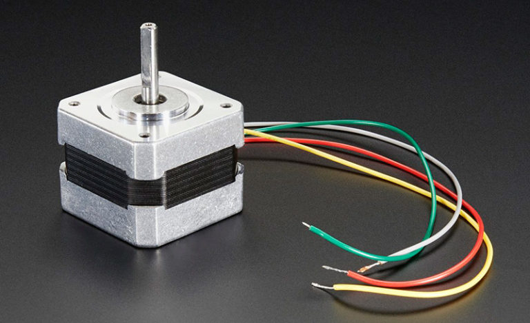
When you first come into contact with a stepper motor, you will notice that the motor has several different colored wires. These colors are not chosen randomly but follow specific industry standards to help technicians quickly identify and correctly connect motor coils. Although there may be slight differences between manufacturers, most stepper motor wire color codes are somewhat universal. In this article we will discuss the color codes, wiring methods, and how to identify the phases of stepper motors.Catalog:
1. What do the stepper motor wire color codes represent?
Stepper motors indicate how the coils are connected by their wire color codes. Often different manufacturers may use different color coding, but for the most part, these color codes follow standard conventions in the industry. Understanding these color codes is the first step to achieving optimal performance from your motor.
2. Stepper motor wire color code
Stepper motor wire color codes are key to achieving correct connections, especially in applications that require precise control of motor movement. While color codes may vary slightly from manufacturer to manufacturer, most follow some form of industry standard.
When wiring a stepper motor, you first need to determine which wires are "paired." These pairs usually correspond to different coils of the motor, such as coil "A" and coil "B". In practice, this might mean identifying the color-coded wires connected to specific coils. For example:
The red and blue wires are usually labeled as the positive connections for the A coil and B coil respectively.
Green and black correspond to the negative poles of these coils respectively.
When operating, you don't need to pay too much attention to the black/green or green/black pin order, it is more important to correctly pair the wires with the same function. For example, placing all positive wires (red, blue) on one side and all negative wires (green, black) on the other side will help simplify the wiring process and reduce errors.
3. How to connect the stepper motor wires
The wiring method of the stepper motor directly determines its performance and applicable scenarios. Understanding the specific applications and technical details of different wiring configurations is key to achieving optimal motor performance. The following is a detailed analysis of three common stepper motor wiring methods:
4-wire stepper motor
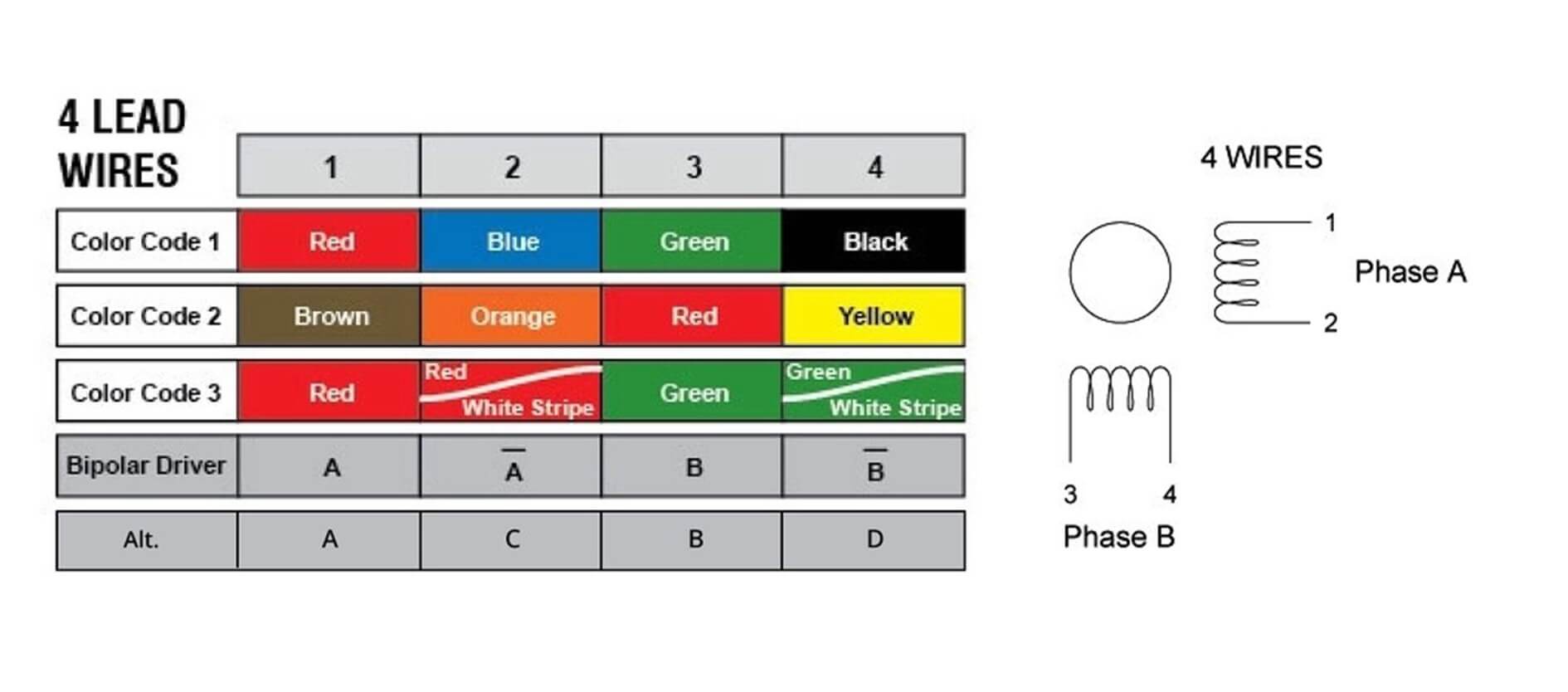
4-wire stepper motors are the most common configuration, especially for applications that don't require excessive complexity. Each phase (A and B) has two wires, generally labeled A and A', B and B'.
When making connections, it is key to find the two wires for each phase and connect them correctly to the corresponding output of the driver. What's intuitive about this configuration is its simplicity, you don't need to worry about center taps or extra wiring complications. The most common mistake is to connect the A-phase and B-phase wires incorrectly, which can cause the motor to vibrate or rotate in the wrong direction.
6-wire stepper motor
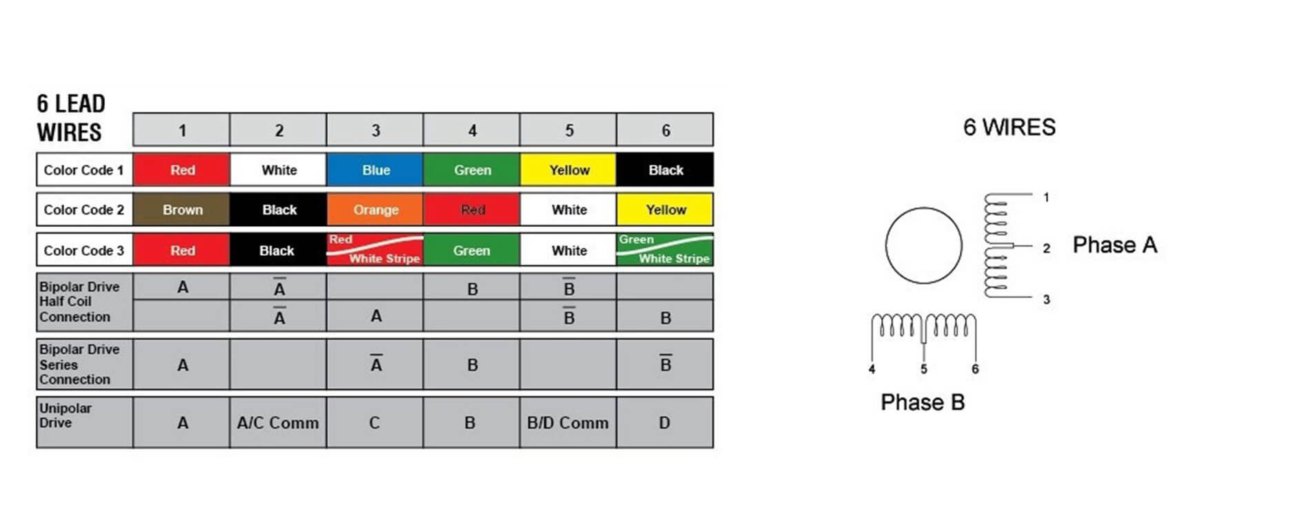
The construction of 6-wire stepper motors is similar to 4-wire, but 6-wire stepper motors add center taps at each end of each phase, allowing the use of unipolar wiring in some configurations, which can provide greater resistance at low speeds. torque.
Identifying the center taps and deciding whether to use them is key with this type of wiring. When not using the center tap, you can simply leave it blank and use the 6-wire motor as a 4-wire motor, but correctly identifying which wires are center tap wires is a must to avoid connection errors.
8-wire stepper motor
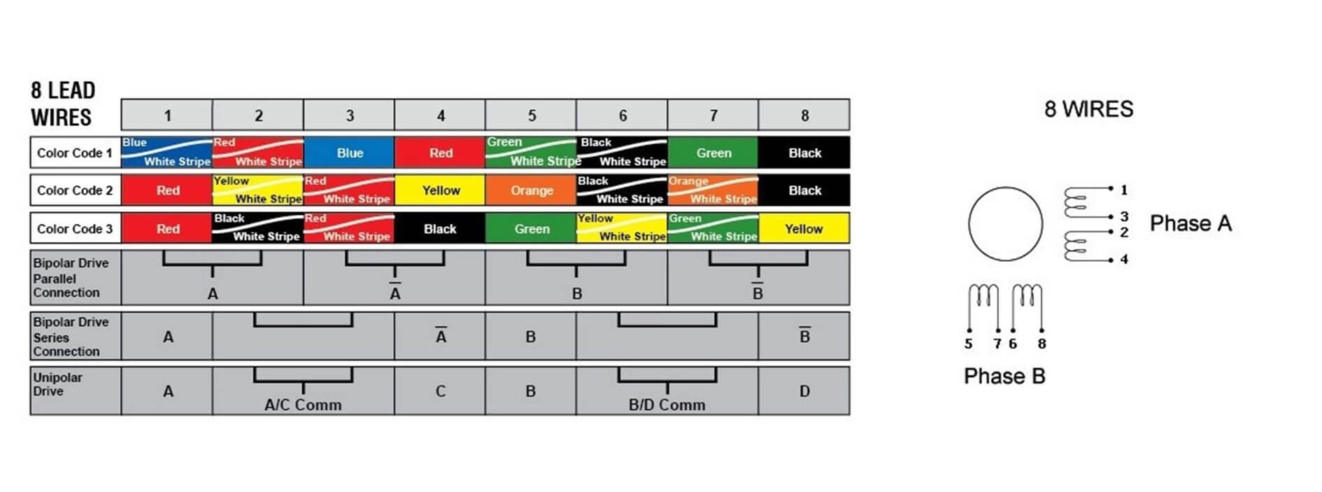
8-wire stepper motors offer maximum flexibility to optimize the motor's speed and torque characteristics through different configurations (series or parallel). The challenge with wiring an 8-wire configuration is deciding the best wiring method. The series configuration provides higher torque at the expense of speed, while the parallel configuration does the opposite. For applications that require fine tuning of motor performance, understanding and implementing these configurations may require more detailed electrical knowledge.
4. Why you need to know the color of stepper motor wires
The wire color of the stepper motor is not just a simple color mark, but each color has a specific meaning, which is directly related to the operating efficiency and direction control of the motor. Mastering these color codes is the basis for ensuring that the stepper motor can work according to the design requirements. Wrong wiring connections may cause motor function failure or even damage the motor.
5. How to identify stepper motor phases - coil pairs
The correct function of a stepper motor relies on the accuracy of the wire pairing. Occasionally, the color code may be inaccurate or become difficult to read in an aging motor, at which point it is necessary to rely on more direct physical testing to identify the coil pair. You can pair stepper motor wires in two ways:
Use a multimeter to detect resistance
Understand the basic principles of resistance testing:
The two wires of each phase should show a small amount of resistance (usually a few ohms) between them, indicating that they are connected to the same coil. Conversely, wires between different phases should have no resistance (i.e. no continuity).
Specific steps:
Set the multimeter to the resistance setting.
Measure the resistance between the two lines that appear to be in phase.
Record the resistance value of each pair of wires to confirm whether they belong to the same phase. Typically, wire pairs of the same phase will show similar resistance values, such as 2.8 Ohm for an XYZ motor and 2.6 Ohm for an extruder motor.
Mechanical testing of stepper motor phases
How to operate the rotation axis test:
With the motor not connected to any drive or power source, manually rotate the motor shaft and feel the resistance of its free rotation.
Select a pair of wires to short-circuit and try rotating the motor shaft again.
If the resistance of the rotating shaft increases significantly, it means that the two wires belong to the same phase; if the resistance does not change significantly, disconnect the pair of wires, select another pair and try again.
When performing the rotary axis test, the operator will feel a clear difference in feel. When the wires are shorted correctly, the resistance of the shaft will increase due to changes in the magnetic field, giving the operator a clear physical feedback that is very intuitive. This test not only verifies that the wires are of the same phase, but also provides a general indication of the integrity of the coil.
6. What will happen if the stepper motor is not wired correctly?
The motor does not rotate:
The stepper motor needs to receive current through its driver in a specific sequence and voltage to drive. If the wires are not properly connected to the corresponding drive terminals, current cannot flow through the motor windings, preventing the motor from starting.
Motor rotation error:
The rotation of a stepper motor depends on the activation sequence of its windings. If the wires of the two coil pairs are swapped, it will cause the phase sequence to be wrong, causing the motor to turn in the wrong direction.
Motor jamming or vibration:
Unstable or loose wire connections will affect the stability of the current received by the motor, causing the motor to run unevenly, manifesting as jamming or vibration.
Motor overheating:
Wiring errors may cause excessive current in the motor windings or incorrect phase sequence. Long-term operation will generate excessive heat, causing the motor temperature to rise, which may damage the insulation layer or other components.
Damage to the motor controller:
If incorrect wiring leads to a short circuit, a large instantaneous current may damage the electronic components of the motor controller.
7. Summary
Understanding and correctly applying stepper motor wire color codes and wiring techniques is important knowledge to ensure motor performance and safe operation. Correct knowledge and skills are key to preventing equipment failure and improving operational efficiency. They are also the driving force for technological innovation and practical development. If you want to know more about stepper motors or have questions, please feel free to contact us.
Frequently Asked Questions [FAQ]
1. What happens if a stepper motor is wired incorrectly?
If a stepper motor is not wired correctly, it can cause a variety of problems. First, the motor may not run at all because the current does not pass through the motor's coils correctly. Second, the motor may run backwards or rotate in the wrong direction, due to the phase sequence between the coils being wired backwards. Even worse, the motor may vibrate, heat up or even burn out if the wires are connected incorrectly causing a short circuit or overload.
2. Do stepper motors need to be grounded?
Stepper motors themselves usually do not need to be grounded because their power supplies and drivers usually already include proper grounding. However, grounding is a necessary safety measure, especially in large mechanical equipment, and ensuring that all electrical systems are grounded prevents accidental electric shocks and electrical interference.
3. How can I tell if a stepper motor is unipolar or bipolar?
The main difference between a unipolar stepper motor and a bipolar stepper motor is the way the coils are wired and the drive requirements. Unipolar motors have a center tap that can be wired separately, while bipolar motors do not have a center tap and both ends of their coils need to be controlled by a driver.
4. What are the positive and negative poles of a stepper motor?
The identification of the positive and negative poles of a stepper motor usually relates to how the motor is driven, especially in bipolar motors. One end of each coil is positive and the other is negative.