TL3845P PWM Controller: Pinout, Key Features, and Layout Tips
In modern electronics, efficient power management is useful for both energy conservation and system performance. Pulse Width Modulation (PWM) controllers play a main role in delivering precise power to various components. This article digs into the details of PWM controllers, starting with the basics of Pulse Width Modulation and its integration into microcontrollers, followed by an in-depth exploration of the TL3845P—a PWM controller known for its robust design and versatile applications. Through this comprehensive guide, you’ll uncover how these controllers enhance system efficiency, noise resistance, and adaptability in power management scenarios.Catalog
Understanding PWM Controllers
Pulse Width Modulation (PWM) employs digital outputs from microprocessors to govern analog circuits, offering a method to vary analog signal levels digitally. This technique is extensively utilized in measurement, communication, and power management, allowing for enhanced system efficiency and lowered power consumption.
Modern microcontrollers often include built-in PWM controllers, facilitating direct digital signaling without the need for digital-to-analog conversion. Digital control reduces noise interference as it only affects digital signals that change binary state, offering an edge over analog systems. Digitally controlling analog circuits offers several benefits including LED dimming through PWM, and eliminating the need for costly dimmer switches. Digital signals within PWM systems resist noise-induced errors, making them valuable in environments with high electromagnetic interference. Improved efficiency results in more streamlined and cost-effective designs.
PWM also has substantial applications in communication systems. Analog signals converted to PWM can be sent over longer distances with reduced noise and then filtered back to analog at the receiver end. This method ensures the integrity of communications, making it requisite in environments prone to electromagnetic interference. PWM controllers play a dangerous role in precise power delivery it is used to regulate voltage in computer power supplies, ensuring both stability and energy efficiency. This precision allows sensitive components to receive steady and reliable power, preventing potential damage and improving overall system longevity.
Aspects of the TL3845P PWM Controller
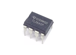
The TL3845P is a Pulse Width Modulation (PWM) controller meticulously crafted for switching power supplies. Responsive to input voltage fluctuations at the COMP terminal, this device finely adjusts the switching signal's frequency to uphold a stable output voltage. The sophisticated internal circuitry boasts a low-voltage lockout (UVLO) that delicately sips under 1 mA of current, alongside a precision reference voltage to sharpen the accuracy of the error amplifier. The ensemble includes a PWM comparator equipped with current limit control, logic for latching operations, and a versatile totem-pole output capable of delivering 200 mA. With an efficient 500 kHz operation frequency and a maximum voltage threshold of 30 V, the TL3845P performs reliably within a temperature spectrum of 0°C to 70°C.
Low Voltage Lockout (UVLO)
Cherished for its ability to protect the system during under-voltage conditions, UVLO averts malfunction by ensuring the controller remains properly biased. This feature proves invaluable in everyday scenarios where power interruptions are frequent, adding an extra layer of assurance and durability to the system.
Precision Reference Voltage
A consistent and precise reference voltage is the cornerstone of the error amplifier's accuracy, having a direct hand in output regulation. This meticulous attention to detail keeps the output steadfast against variations, a trait especially prized in high-performance electronic devices.
PWM Comparator with Current Limit Control
The pulse-width modulation comparator, integrated with current limit control, is instrumental in sustaining system stability and efficiency. By manipulating the current, the comparator alleviates the perils of overheating and undue component stress, thus fortifying the longevity of the power supply.
Latching Logic Mechanism
The latching logic mechanism, ingrained in the TL3845P, orchestrates predictable and controlled switching sequences. This regulation aspect is active in intricate systems where synchronized operations are dominant.
Totem-Pole Output
Boasting a versatile totem pole output capable of 200 mA, the TL3845P demonstrates strength in versatility and efficiency. Operating smoothly at frequencies up to 500 kHz, the output stage ensures adept handling of various power demands.
Equivalent Models
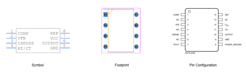
TL3845P Pinout, Symbol, and PCB Footprint
Below is the symbol, Footprint, and pin configuration representation of the TL3845P.
Features and Specifications of the TL3845P PWM Controller
The TL3845P PWM controller is meticulously designed with a range of advanced features aimed at optimizing performance in various power conversion applications. The low output resistance error amplifier ensures precise error correction, an ultimate aspect of maintaining voltage stability. Moreover, a hysteretic Undervoltage lockout (UVLO) mechanism offers robust protection by avoiding erroneous operations due to low voltage situations, keeping the system safe until normal conditions are restored.
Enhanced Protection Mechanisms
The architecture includes double pulse suppression, required for averting erroneous pulses resulting from noise or transient conditions. This feature suggestively boosts system reliability by ensuring only valid pulses influence the switching events.
Efficient Power Consumption
A standout characteristic is its low startup current requirement, less than 1mA. This efficiency is highly beneficial in energy-sensitive applications, such as battery-operated devices, where reducing power consumption during startup can substantially extend operational life.
Automatic Performance Optimization
Automatic feed-forward compensation is a noteworthy feature. It dynamically adjusts control parameters to offset variations in input voltage, enhancing converter performance across a broad spectrum of operating conditions. This adaptability echoes applications where such variations are common.
Output Power Management
The high current totem pole output structure is engineered to provide substantial output drive capability. This enables efficient control over power transistors. Pulse-by-pulse current limiting further protects against overcurrent conditions, a major aspect in industrial contexts where high currents could inflict damage.
Load Handling and Response
Enhanced load response characteristics allow the controller to swiftly adjust to changes in load demand, ensuring stability and performance. This capability is mostly active in dynamic environments where load conditions can change rapidly, such as in telecommunications or computing systems.
Analyzing the Technical Parameters of TL3845P
|
Product Attribute |
Attribute Value |
|
Manufacturer |
Texas Instruments |
|
Package / Case |
PDIP-8 |
|
Packaging |
Tube |
|
Length |
9.81 mm |
|
Width |
6.35 mm |
|
Height |
4.57 mm |
|
Switching Frequency |
500 kHz |
|
Rise Time |
50 ns |
|
Fall Time |
50 ns |
|
Operating Supply Current |
11 mA |
|
Operating Supply Voltage |
7.6V~30V |
|
Operating Temperature |
0°C ~ 70°C |
|
Part Status |
Active |
|
Pin Count |
8 |
|
Number of Outputs |
1 Output |
|
Mounting Style |
Through Hole |
|
Product Type |
Switching Controllers |
Operating Principle of TL3845P PWM Controller
Initial Activation and Error Amplification
When power is supplied to the VCC pin of the TL3845P, the chip initiates its function by energizing the internal circuits. The process unfolds as the feedback voltage enters the error amplifier. This amplifier continuously compares the feedback voltage with a stable reference voltage. The difference between these voltages produces an error signal, which serves as the foundation for subsequent processing. This process embodies the vigilance and precision desired to maintain the accuracy required for optimal performance.
PWM Signal Generation
The error signal, once generated, is handed off to the PWM comparator. The comparator, central to the PWM control mechanism, crafts a precise PWM signal from the error input. The duty cycle of this PWM signal is closely dependent on the input voltage. A higher input voltage results in a proportionally longer duty cycle. Conversely, a lower input voltage leads to a shorter duty cycle.
This modulation fine-tunes the switch tube’s on and off intervals, stabilizing the output voltage. Practically, this ensures consistent output even amidst fluctuating input conditions, empowering the system with the reliability and adaptability it needs to thrive.
Current Limiting and Overload Protection
Integrated within the TL3845P is a function dedicated to current limiting. This feature is vigilant in monitoring and controlling the output current, shielding the switch tube from potential overload situations. By curtailing current flow when it crosses safe thresholds, the controller upholds the integrity and longevity of the system components. In practical scenarios, this protection mechanism stands as a sentinel, preempting hardware damage and ensuring sustained performance under varying load conditions. This embodies a layer of defense requisite in maintaining the resilience and durability of the system.
Use Cases for the TL3845P PWM Controller
Utilization in Power Supply Systems
The TL3845P plays a major role in a diverse array of power supply systems, especially within the industrial and communication equipment sectors. Its PWM control capabilities facilitate effective energy management and reliable performance, ensuring consistent operation despite fluctuating load conditions. In environments where power integrity defines operational success, the TL3845P stands as a steadfast guardian of stability.
Consumer Electronics
Employed extensively in consumer electronics, the TL3845P graces devices such as computers, mobile phones, and televisions. These applications reap the rewards of the controller's precise power regulation, bolstering device efficiency and extending battery lifespan. The TL3845P's adeptness at swiftly accommodating shifts in power demands fosters seamless operation and optimizes overall device performance.
Isolated Flyback Power Controller
One distinguished functionality of the TL3845P lies in its role as an isolated flyback power controller. This application is focal in ensuring steady voltage and current output regulation, which is beneficial for devices dependent on a stable power supply. The robust regulation mechanism remarkably enhances transient response, equipping systems to adeptly manage abrupt surges in power demand while preserving stability and performance.
Enhancement of Transient Response
In power-sensitive environments, the TL3845P's quick adaptation to load variations proves immensely valuable. The heightened transient response achieved through continuous voltage and current output regulation bolsters operational precision and reliability. This feature shines in high-precision, robust scenarios, such as communication equipment, where maintaining an uninterrupted power supply is a must.
Designing the PCB: Layout Guidelines for the TL3845P
Select the Right Inductor
When choosing an inductor, opt for one with low Electromagnetic Interference (EMI) and a ferrite core. Toroid and encased E-core inductors are excellent options. If using inductors with open cores, ensure they still exhibit low EMI characteristics. These should be strategically placed away from low-power traces and sensitive components to minimize interference.
Optimal Placement of External Components
Position external compensation components close to the Integrated Circuit (IC). Surface-mounted devices are preferable for this purpose. This setup minimizes noise and signal interference, which is dynamic for the stability and performance of the system.
Effective Design of Feedback Traces
The design of feedback traces should emphasize being as direct and thick as possible. Ensure these traces maintain a safe distance from noise sources and are located on the PCB side opposite to the inductors. Separate these traces with a ground plane, which greatly reduces the potential for noise coupling.
Strategic Capacitor Positioning
Place input and output capacitors close to the IC to minimize inductance effects. Using surface-mounted capacitors is recommended to reduce lead length and associated noise. This approach enhances voltage regulation stability.
Efficient Power Traces and Grounding
Design power traces to be short, direct, and thick. Adhere to a minimum width of 15 mils per ampere. Ground connections should be placed as close to each other as possible, with a fully dedicated ground plane on the PCB. Implementing ground planes on both sides of the PCB effectively reduces noise by minimizing ground loop errors and absorbing EMI, thereby improving overall circuit performance.
Considerations for Multi-Layer Boards
For multi-layer boards, separate power and signal planes with ground planes. Use standard vias capable of conducting the required current between layers. It is used to ensure current loops curl in the same direction in both power states to avoid magnetic field reversals, which helps in reducing EMI.
Frequently Asked Questions [FAQ]
1. What are the typical applications of the TL3845P IC?
The TL3845P IC is found to be extensively used in DC-DC converters, voltage regulators, and power supplies across various electronic systems. It plays a substantial role in power management, basic telecommunications infrastructure, industrial automation, and consumer electronics systems. For example, telecommunications stabilize power for signal processing units, ensuring continuous and reliable communication. It helps maintain smooth operations in industrial automation systems by providing regulated power. In consumer electronics, it enhances the performance and lifespan of devices by ensuring efficient power distribution.
2. What is the replacement and equivalent of TL3845P?
Several ICs can replace the TL3845P, including TL3843P. TL3844P, AND TL3845PE4. These alternatives offer similar functionalities, ensuring minimal disruption when substituting components. For instance, engineers might opt for the TL3843P in existing designs requiring tight voltage regulation, while the TL3845PE4 could provide enhanced efficiencies in newer applications.
3. What is the TL3845P IC used for?
The TL3845P functions predominantly as a PWM voltage mode controller in power supply and voltage regulation applications. This ensures stable output voltages under varying load conditions, dangerous for computer power supplies, and maintaining safe voltage limits for processors. Electric vehicles, controlling power distribution systems, and enhancing battery life and overall vehicle performance.
4. What protections or features does the TL3845P provide?
The TL3845P IC is equipped with multiple protection features including overcurrent protection, overvoltage protection, under-voltage lockout, and a soft start feature. These protections contribute to a safer operational environment by mitigating the risks of component damage. For instance, the soft start feature gradually increases the power supply during system startups, preventing sudden surges and extending the IC's and the system's lifespan, akin to gradually intensifying tasks to avoid burnout.
About us
ALLELCO LIMITED
Read more
Quick inquiry
Please send an inquiry, we will respond immediately.
S9015 PNP Transistor: Equivalent Models, Structural Insights, and C9015 Comparison
on September 27th
A Complete Guide to the CD4046BE and Its Applications
on September 27th
Popular Posts
-

What is GND in the circuit?
on January 1th 3142
-

RJ-45 Connector Guide: RJ-45 Connector Color Codes, Wiring Schemes, R-J45 Applications, RJ-45 Datasheets
on January 1th 2689
-

Understanding Power Supply Voltages in Electronics VCC, VDD, VEE, VSS, and GND
on November 15th 2260
-

Fiber Connector Types: SC Vs LC And LC Vs MTP
on January 1th 2194
-

Comparison Between DB9 and RS232
on January 1th 1806
-

What Is An LR44 Battery?
Electricity, that ubiquitous force, quietly permeates every aspect of our daily lives, from trivial gadgets to life-threatening medical equipment, it plays a silent role. However, truly grasping this energy, especially how to store and efficiently output it, is no easy task. It is against this background that this article will focus on a type of coin cell battery that may seem insignificant on the...on January 1th 1781
-

Understanding the Fundamentals:Inductance Resistance, andCapacitance
In the intricate dance of electrical engineering, a trio of fundamental elements takes center stage: inductance, resistance, and capacitance. Each bears unique traits that dictate the dynamic rhythms of electronic circuits. Here, we embark on a journey to decipher the complexities of these components, to uncover their distinct roles and practical uses within the vast electrical orchestra. Inductan...on January 1th 1735
-

CR2430 Battery Comprehensive Guide: Specifications, Applications and Comparison to CR2032 Batteries
What is CR2430 battery ?Benefits of CR2430 BatteriesNormCR2430 Battery ApplicationsCR2430 EquivalentCR2430 VS CR2032Battery CR2430 SizeWhat to look for when buying the CR2430 and equivalentsData Sheet PDFFrequently Asked Questions Batteries are the heart of small electronic devices. Among the many types available, coin cells play a crucial role, commonly found in calculators, remote controls, and ...on January 1th 1690
-

What Is RF and Why Do We Use It?
Radio Frequency (RF) technology is a key part of modern wireless communication, enabling data transmission over long distances without physical connections. This article delves into the basics of RF, explaining how electromagnetic radiation (EMR) makes RF communication possible. We will explore the principles of EMR, the creation and control of RF signals, and their wide-ranging uses. The article ...on January 1th 1688
-

Comprehensive guide to hFE in transistors
Transistors are crucial components in modern electronic devices, enabling signal amplification and control. This article delves into the knowledge surrounding hFE, including how to select a transistor's hFE value, how to find hFE, and the gain of different types of transistors. Through our exploration of hFE, we gain a deeper understanding of how transistors work and their role in electronic circu...on November 15th 1650
HOT Part Number
-

BZV55C12
Microchip Technology
DIODE ZENER
TFA9887UK/N1,023
NXP Semiconductors
AUDIO AMPLIFIER, 1 FUNC, PBGA29
IRF6665TRPBF
International Rectifier
IRF6665 - 12V-300V N-CHANNEL POW
TLC1541IFN
Texas Instruments
IC ADC 10BIT SAR 20PLCC
DF40C-80DS-0.4V(51)
Hirose Electric Co Ltd
CONN RCPT 80POS SMD GOLD
LTC3221EDC-5#TRMPBF
Analog Devices Inc.
IC REG CHARGE PUMP 5V 60MA 6DFN
FCPF22N60NT
onsemi
MOSFET N-CH 600V 22A TO220F
LT1009CD
Texas Instruments
IC VREF SHUNT 0.4% 8SOIC
SI4906DY-T1-E3
Vishay Siliconix
MOSFET 2N-CH 40V 6.6A 8-SOIC
VI-J3Y-EW
Vicor Corporation
DC DC CONVERTER 3.3V 66W
FDB4020P
onsemi
MOSFET P-CH 20V 16A TO263AB
MCC95-08IO1B
IXYS
MOD THYRISTOR DUAL 800V TO-240AA
S-817B11AMC-CWAT2G
ABLIC Inc.
IC REG LINEAR 1.1V 20MA SOT23-5
VI-JW1-EY
Vicor Corporation
DC DC CONVERTER 12V 50W
AUIRF7484QTR
International Rectifier
AUTOMOTIVE N CHANNEL
S25FL128SAGMFI010
Infineon Technologies
IC FLASH 128MBIT SPI/QUAD 16SOIC
RL2512FK-070R18L
YAGEO
RES 0.18 OHM 1% 1W 2512
M-FIAM9H22
Vicor Corporation
FILTER MILITARY COTS 28 VIN -
MSP430G2210ID
Texas Instruments
IC MCU 16BIT 2KB FLASH 8SOIC
AD7418ARM
Analog Devices Inc.
SENSOR DIGITAL -40C-125C 8MSOP
LB1909MC-BH
onsemi
IC MTR DRV BIPOLR 2.5-16V 10SOIC
74LCX646MSA
Fairchild Semiconductor
IC TXRX NON-INVERT 3.6V 24SSOP
0603YA270K4T2A
KYOCERA AVX
CAP CER 27PF 16V NP0 0603
ATMEGA169V-8AU
Atmel
IC MCU 8BIT 16KB FLASH 64TQFP
P6SMB200AHE3/52
Vishay General Semiconductor - Diodes Division
TVS DIODE 171VWM 274VC DO214AA
VI-26H-MV
Vicor Corporation
DC DC CONVERTER 52V 150W
PCI2050GHK
Texas Instruments
IC INTERFACE SPECIALIZED 209BGA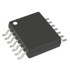
AD8604ARUZ
Analog Devices Inc.
IC CMOS 4 CIRCUIT 14TSSOP
MPC8313VRAFF
NXP USA Inc.
IC MPU MPC83XX 333MHZ 516BGA
LSM115JE3/TR13
Microchip Technology
DIODE SCHOTTKY 15V 1A DO214BA
BDX34C
onsemi
TRANS PNP DARL 100V 10A TO220
74F37PC
onsemi
IC GATE NAND 4CH 2-INP 14DIP
5022443330
Molex
CONN FFC BOTTOM 33POS 0.5MM R/A
L6225N
STMicroelectronics
IC MTR DRV BIPLR 8-52V 20-PWRDIP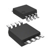
MC10EPT20DTR2
onsemi
IC TRANSLATOR UNIDIR 8TSSOP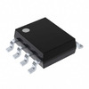
MAX6126BASA50+
Analog Devices Inc./Maxim Integrated
IC VREF SERIES 0.06% 8SOIC -

SMDJ40CA
Meritek
TVS DIODE 40VWM 64.5VC
PMV30XN,215
NXP USA Inc.
MOSFET N-CH 20V 3.2A TO236AB
TNPW04021K50BEED
Dale / Vishay
RES 1.5K OHM 0.1% 1/10W 0402
KSZ8091RNBCA
Microchip Technology
IC TRANSCEIVER FULL 1/1 32QFN
MSP430FE4252IPMR
Texas Instruments
IC MCU 16BIT 16KB FLASH 64LQFP
EP3SE80F1152I3
Intel
IC FPGA 744 I/O 1152FBGA
74F240PC
onsemi
IC BUFFER INVERT 5.5V 20DIP
UMF325B7223KNHT
Taiyo Yuden
CAP CER 0.022UF 50V X7R 1210
CL31B106KAHSFNE
Samsung Electro-Mechanics
CAP CER 10UF 25V X7R 1206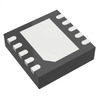
ADP1871ACPZ-0.6-R7
Analog Devices Inc.
IC REG CTRLR BUCK 10LFCSP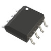
OP193FS-REEL
Analog Devices Inc.
IC OPAMP GP 1 CIRCUIT 8SOIC
LTC2376CMS-20#TRPBF
Analog Devices Inc.
IC ADC 20BIT SAR 16MSOP
CY7C131E-55JXC
Infineon Technologies
IC SRAM 8KBIT PARALLEL 52PLCC
LMX2324TM
Texas Instruments
IC PLL FREQ SYNTH 16TSSOP
UCC2813QDR-3Q1
Texas Instruments
IC REG CTRLR MULT TOPOLOGY 8SOIC
1812JC470JAT1A
KYOCERA AVX
CAP CER 47PF 4KV X7R 1812
2SD1207S-AE
Sanyo
TRANS NPN 50V 2A 3MP
AU1PD-M3/84A
Vishay General Semiconductor - Diodes Division
DIODE AVALANCHE 200V 1A DO220AA