470 Ohm Resistor
A 470-ohm resistor helps control the flow of electricity in circuits. Though simple, it plays an important role in the function of devices, from small household items to large machines. Marked by yellow, violet, and brown color bands, this resistor ensures the correct amount of electricity flows through, protecting other parts and helping the device function properly. In electronics, knowing how to read resistor color codes is a required skill. This article looks closely at the 470 ohm resistor and explains the meaning of its color bands in different systems, like the four-band, five-band, and six-band types. These bands show the resistor's value, along with other details like tolerance and temperature changes, which help make sure circuits work correctly. By breaking down each band system, the article helps improve understanding of resistor codes that can make circuit design and fixing electronic problems easier.Catalog
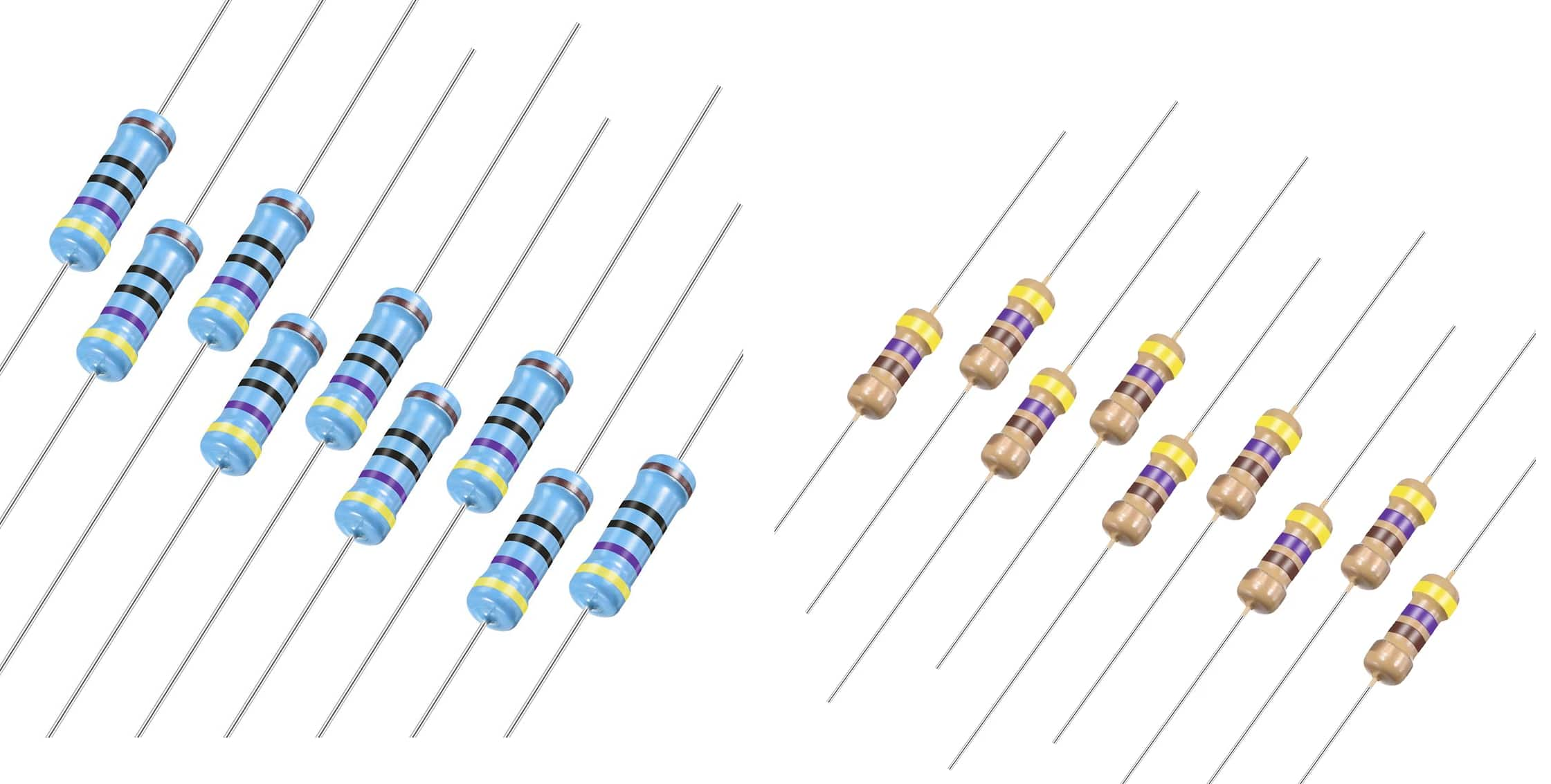
Figure 1: 470 Ohm Resistor 4 Band and 5 Band
What Is a 470 Ohm Resistor?
The 470-ohm resistor is useful in electronic circuits because it limits the flow of electrical current. It creates 470 ohms of resistance that helps keep the current at safe levels, protecting other components from getting too hot or damaged. By lowering the current, it keeps the circuit stable and reliable. This resistor can handle currents close to 1 amp and voltages up to 470 volts, making it useful in many different applications.
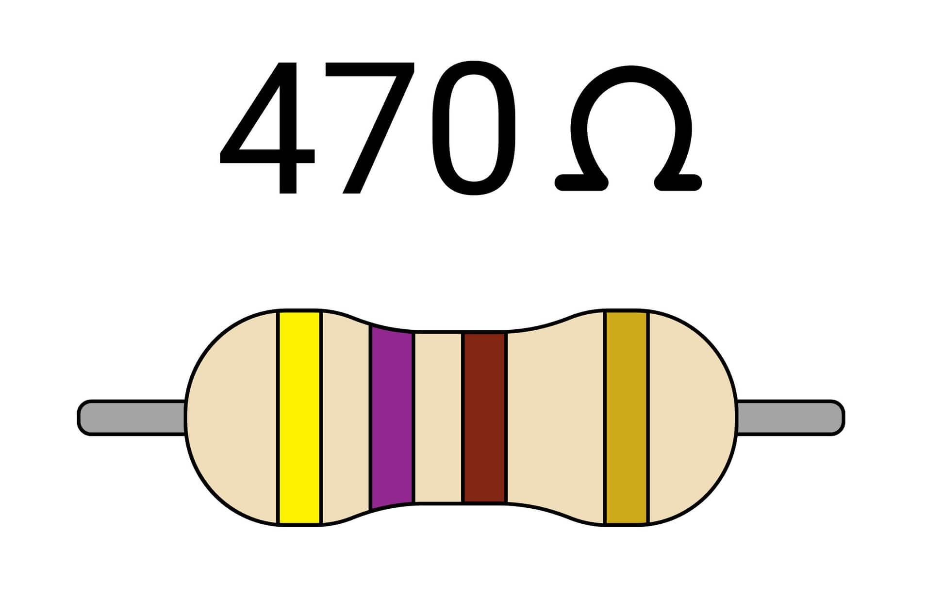
Figure 2: 470 Ohm Resistor
In circuits, the 470-ohm resistor serves several purposes. It's used to adjust the voltage that goes to different parts of a system that helps power delicate components safely. It can also fine-tune circuits, when precise control of current is required. In communication systems, it helps keep signals clear by reducing any interference, ensuring accurate data transmission. By matching impedance, it also helps different devices communicate smoothly.
Color Code of a 470 Ohm Resistor
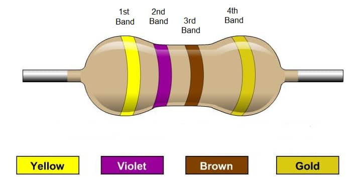
Figure 3: 470 Ohm Resistor
Resistor Type Band One (1st digit) Band Two (2nd digit) Band Three (3rd digit/Multiplier) Band Four (Multiplier/Tolerance) Band Five (Tolerance) Band Six (Temperature Coefficient)
|
Resistor Type |
Band One (1st
digit) |
Band Two (2nd
digit) |
Band Three
(3rd digit/Multiplier) |
Band Four (Multiplier/Tolerance) |
Band Five
(Tolerance) |
Band Six
(Temperature Coefficient) |
|
Four Band |
Yellow (4) |
Violet (7) |
Brown (x10) |
± % |
– |
– |
|
Five Band |
Yellow (4) |
Violet (7) |
Black (0) |
Black (x1) |
± % |
– |
|
Six Band |
Yellow (4) |
Violet (7) |
Black (0) |
Black (x1) |
± % |
R(T°) |
The color code on a 470-ohm resistor is a simple way to quickly know its resistance and other details. It uses colored stripes on the resistor to show numbers and multipliers. For a 470-ohm resistor with four bands, the colors are yellow, violet, brown, and gold. Yellow stands for 4, violet for 7, and brown means multiplying by 10, giving 470 ohms. The gold band shows a tolerance of ±5%, meaning the actual resistance can range from 446.5 ohms to 493.5 ohms.
Some resistors have five or six bands that give more precise information. The fifth band adds another number, while the sixth (rare for basic resistors like the 470-ohm) shows how the resistance changes with temperature.
Misreading these codes can lead to using the wrong resistor and may cause the circuit to malfunction or perform poorly. To avoid this, always double-check the color bands and confirm the resistor's value with a multimeter. Learning the color coding system makes assembling, troubleshooting and maintaining circuits easier, ensuring they work correctly.
The 470-Ohm Resistor Color Bands
Resistor color bands help you figure out the exact resistance value of a resistor. A 470-ohm resistor, like others, uses a color code that changes depending on whether it has four, five, or six color bands. Each extra band gives more detail and precision.
Four-Band Resistors
In a four-band resistor, the first two bands represent the significant digits of the resistance value. For a 470-ohm resistor, the first band is yellow (representing "4") and the second band is violet (representing "7"). The third band is the multiplier, which is orange, meaning the digits should be multiplied by 1000. The fourth band, usually gold or silver, indicates the tolerance or how much the actual resistance may vary from the stated value. Gold represents a ±5% tolerance, so the resistance could range from 446.5 ohms to 493.5 ohms.
Five-Band Resistors
In a five-band resistor, a third digit band is added before the multiplier, providing greater precision in the resistor's value. Using the 470-ohm resistor as an example, the first three bands could be yellow, violet, and black, representing "4", "7", and "0". The fourth band, orange, is the multiplier, still meaning a multiplication by 1000. The fifth band continues to indicate tolerance.
Six-Band Resistors
A six-band resistor includes all the information of a five-band resistor, but it adds a sixth band that indicates the temperature coefficient. This coefficient tells how much the resistance will change with temperature variations, usually expressed in parts per million per degree Celsius (ppm/°C). The sixth band ensures the resistor will maintain stability in temperature-sensitive applications.
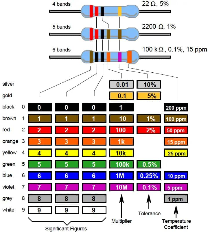
Figure 4: The 470-Ohm Resistor Color Bands
How to Decode Resistor Color Bands?
|
Band Number |
Function |
Color |
Value |
|
1 |
1st Digit |
Yellow |
4 |
|
2 |
2nd Digit |
Violet |
7 |
|
3 |
Multiplier |
Brown |
x 10 |
|
4 |
Tolerance |
Gold (or Silver) |
± 5% (± 10% for silver) |
|
Total Value: 470 ± 5% Ω |
|||
Decoding the color bands of a 470-ohm resistor follows a systematic process to ensure accurate interpretation of its value and characteristics:
• Locate the Tolerance Band
Start by finding the tolerance band, usually gold or silver. This band is slightly separated from the others in four and five-band resistors, making it easy to identify.
• Check for Temperature Coefficient
If you're dealing with a six-band resistor, identify the last two bands. The final band indicates the temperature coefficient, which is good in precise circuits that need to stay stable at different temperatures.
• Read the Value from Left to Right
Starting with the first band on the left, determine the significant digits, followed by the multiplier band. For example, in a 470-ohm resistor, the yellow and violet bands represent "47". When multiplied by the orange band's 1000, the nominal resistance is confirmed as 470 ohms.
How To Read the 470 Ohm Resistor Color Code?
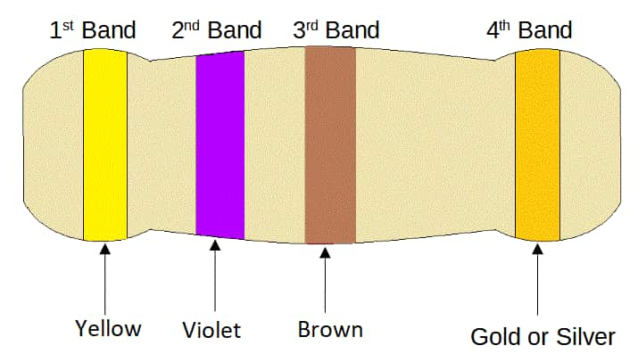
Figure 5: 470 Ohm Resistor
The color code for a 470-ohm resistor uses a standardized system to represent resistor values. This system relies on colored bands printed on the resistor, where each color corresponds to a specific number, multiplier, or tolerance level.
To read the color code for a 470-ohm resistor, you start with the first band, which indicates the first digit of the value. For 470 ohms, the first digit is "4," represented by yellow.
The second band shows the second digit, which is "7," and is represented by violet.
The third band gives the multiplier, which in this case is 101, meaning we multiply 47 by 10 to get 470. This is represented by brown, stands for a multiplier of 1.
The fourth band shows the tolerance, or how much the actual resistance can vary from the stated value. For most common resistors, the tolerance is ±5%, indicated by a gold band.
Therefore, the full color code for a 470-ohm resistor is Yellow, Violet, Brown, and Gold. This is the process for identifying a 470-ohm resistor using the color coding system.
4-Band vs. 5-Band vs. 6-Band 470 Ohm Resistor Color Code
Resistor color codes are important system in electronics used to quickly identify resistor values. These codes, represented by colored bands on the resistor's body, range from the simpler 4-band system to the more detailed 5-band and 6-band versions. With each additional band, more specific information about the resistor's properties is provided, offering greater precision. As electronics have become more complex, the need for resistors with enhanced accuracy and additional specifications has grown. This evolution addresses everything from basic resistance values to more advanced characteristics like temperature sensitivity.
|
Band Number |
4-Band
Resistor |
5-Band
Resistor |
6-Band
Resistor |
|
1st |
Yellow (4) |
Yellow (4) |
Yellow (4) |
|
2nd |
Violet (2) |
Violet (2) |
Violet (2) |
|
3rd |
Brown (Multiplier x10) |
Black (0) |
Black (0) |
|
4th |
Gold (Tolerance ±5%) |
Black (Multiplier x1) |
Black (Multiplier x1) |
|
5th |
N/A |
Gold (Tolerance ±5%) |
Gold (Tolerance ±5%) |
|
6th |
N/A |
N/A |
Temperature Coefficient |
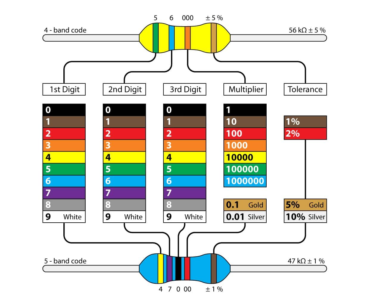
Figure 6: Resistor Color Code 4-Band and 5-Band System
The 4-band system is used for general purposes but as technological demands have increased, the need for greater precision has led to the development of the 5-band and 6-band systems. These newer systems provide more detailed information, such as tighter tolerances and temperature coefficients in high-precision applications.
The 5-band resistor color code offers more precise identification than the 4-band system. For a 470-ohm resistor, the colors yellow, violet, and black represent the digits 4, 7, and 0, forming the base value of 470 ohms. The fourth band, often brown, acts as a multiplier, adjusting the total value to 4700 ohms. The fifth band, gold or silver, indicates tolerance, with common values being ±5% or ±10%.
The shift from the 4-band to the 5-band resistor system reflects the growing need for precise electronic components. While the 4-band system uses two significant digits, a multiplier, and a tolerance band, the 5-band system adds a third significant digit, increasing the accuracy of the resistor's value. This additional digit allows for finer control over resistance values, reducing errors in high-precision electronic components. The visual layout of the 5-band system makes it easier to distinguish between value and tolerance bands, improving readability and component identification.
The 6-band resistor color code expands on the 5-band system by introducing a sixth band that represents the resistor's temperature coefficient. This extra band is excellent in circuits sensitive to temperature changes, as it provides information about how the resistor's value shifts as temperatures vary. For a 470-ohm resistor, this sixth band ensures that the resistor maintains stable performance, even in environments where temperature fluctuations are common. This feature makes 6-band resistors use for high-precision applications where thermal stability is need to maintain consistent circuit performance.
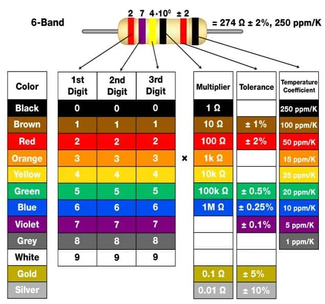
Figure 7: The 6-band Resistor Color Code
Applications of 470 Ohm Resistor
Signal Processing
The 470 ohm resistor plays a role in maintaining signal integrity in various signal processing tasks. It's commonly used in circuits like voltage dividers, filters, and biasing setups to manage signal levels and set reference voltages. This is important for making sure downstream components work properly. For example, in a voltage divider, the resistor adjusts the output voltage to the right level, and for improving the circuit's performance.
In filter circuits, it helps set the cutoff frequencies, determining which signal bandwidths are allowed to pass. This is useful for tasks like high-fidelity audio processing or data communication, where clarity and efficiency are priorities. When used in biasing circuits, the 470 ohm resistor helps establish the right operating conditions for transistors, ensuring they perform well in either amplification or switching modes. By keeping the transistors operating in their optimal range, it helps reduce signal distortion and maintains consistent performance in amplification stages.
Power Management
In power management circuits, the 470-ohm resistor helps control voltage and current. One common use is in voltage regulation circuits, where it helps stabilize output voltage, ensuring that power supplies deliver consistent and reliable performance. This resistor also allows fine adjustments in the feedback loop of voltage regulators, enabling precise control of the voltage supplied to electronic devices. This fine-tuning helps prevent voltage discrepancies that could disrupt operation or damage sensitive components. In current-limiting circuits, the 470 ohm resistor restricts current flow to safe levels, helping protect the system from overcurrent conditions that could lead to overheating or failure.
Circuit Protection
The 470-ohm resistor is useful for protecting circuits from too much current or sudden voltage increases. It helps limit the amount of current flowing through a system, which prevents overloads, during power surges or when a device first starts up. This resistor is also used to handle sudden voltage spikes, like those caused by static electricity or lightning, keeping delicate parts like microprocessors and memory chips safe. By controlling these spikes, the 470-ohm resistor makes electronic circuits more durable and reliable, helping devices last longer.
How to Test the Resistance Value of a 470 Ohm Resistor with a Multimeter?
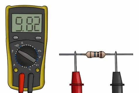
Figure 8: Test Resistance with a Multimeter
Testing a 470 ohm resistor with a multimeter requires some basic knowledge and attention to detail. A multimeter is a versatile tool that measures electrical properties like resistance and voltage. In this guide, we'll focus on setting up the multimeter, testing the resistor, and interpreting the results in a clear, straightforward manner.
Before you start testing, it's required to properly configure the multimeter. First, make sure the multimeter is turned off. This prevents incorrect readings or potential damage. Once it's off, turn the dial to the resistance setting, marked with the Ω (Omega) symbol. It's worth noting that modern digital multimeters often have additional features like measuring capacitance, current, and continuity, so be sure you're in the right mode.
Next, check that the multimeter is calibrated correctly. To do this, touch the two probes, one red and one black, together. The display should show zero ohms, indicating no resistance between the probes. If you get a different reading, the multimeter may need recalibration, or there might be an issue with the probes or batteries. Proper calibration ensures accurate measurements.
Now that the multimeter is set up, you can test the 470 ohm resistor. Attach the red probe to one end of the resistor and the black probe to the other. Ensure that the probes make firm contact with the resistor leads to avoid inaccurate readings. If the connection is loose, the measurement may fluctuate or be incorrect.
Handle the resistor carefully during testing. Avoid touching the body of the resistor with your fingers, as the heat from your hand can slightly alter the resistance reading. Hold the leads instead, or use a breadboard to stabilize the resistor.
Once the probes are properly connected, look at the display on the multimeter. For a 470 ohm resistor, the expected value should be around 470 ohms. However, resistors come with a tolerance range, typically ±5% or ±10%. This means a reading between 446.5 ohms (470 - 5%) and 493.5 ohms (470 + 5%) is acceptable. If the reading falls outside this range, it could indicate a problem with the resistor, such as damage or a manufacturing flaw.
After you've obtained the reading, compare it with the resistor’s expected value. If the measurement is within the tolerance range, the resistor is in good condition and can be used in a circuit without issues. If the reading is too high or too low, recheck the connection, and if the result is still off, the resistor may need to be replaced. In some cases, environmental factors like temperature could also affect the measurement, so testing in different conditions might be useful.
Conclusion
Understanding the color coding of resistors, like the 470-ohm resistor, is important for designing and fixing electronics correctly. This article has clearly explained what each color band means in different resistor setups, showing how extra bands improve accuracy and flexibility in electronics. Whether it's for simple tasks or more complex systems, the 470-ohm resistor is useful keeping circuits work properly. The step-by-step instructions on using a multimeter to check resistor values highlight the need for careful work in electronics. By learning the color code system and how to apply it, electronics experts can make sure their projects work well, even with changes in temperature and power.
Frequently Asked Questions [FAQ]
1. How to identify a 470 ohm resistor?
To identify a 470 ohm resistor, check the color bands around the resistor. A 470 ohm resistor will have the following color bands: Yellow, Violet, Brown, and Gold. Yellow represents the number 4, Violet stands for 7, and Brown means that these two numbers should be followed by one zero (as indicated by the multiplier of 10 from the Brown band). The Gold band indicates a tolerance of ±5%.
2. What is the power rating of a 470 ohm resistor?
The power rating of a resistor, which indicates how much power it can handle before it risks damage, is not determined by its resistance value alone. Resistor power ratings are found on the resistor's packaging or datasheet. Common ratings for small resistors are 1/4 watt or 1/2 watt. You need to ensure the resistor's power rating matches or exceeds the power it will dissipate in your circuit.
3. What is the voltage drop of a 470 ohm resistor?
To calculate the voltage drop across a 470 ohm resistor, you need to know the current flowing through it. The formula is V = IR, where V is voltage, I is current, and R is resistance. If you do not know the current, you cannot calculate the voltage drop directly without more information about how the resistor is connected in the circuit.
4. What is a substitute for a 470 ohm resistor?
A direct substitute for a 470 ohm resistor would be any resistor with the same resistance and at least the same power rating. However, depending on the tolerance required in your circuit, resistors with values close to 470 ohms, such as 460 ohm or 480 ohm, could potentially be used. Always ensure the substitute's power rating and tolerance are appropriate for your application.
5. What is the result of connecting a red LED with a 470 ohm resistor to a 9 volt battery?
When you connect a red LED and a 470 ohm resistor in series with a 9-volt battery, the LED will light up, assuming correct polarity (longer leg of the LED connected towards the positive terminal of the battery through the resistor). The resistor limits the current flowing through the LED, protecting it from excessive current that could cause damage.
Here’s the practical setup:
Connect the positive terminal of the 9V battery to one end of the 470 ohm resistor.
Connect the other end of the resistor to the longer leg (anode) of the red LED.
Connect the shorter leg (cathode) of the LED to the negative terminal of the battery.
This setup ensures the LED operates safely without burning out, as the resistor reduces the current flowing through the LED to a safe level.
About us
ALLELCO LIMITED
Read more
Quick inquiry
Please send an inquiry, we will respond immediately.
47k Ohm Resistor: Color Codes and Applications
on September 10th
1k Ohm Resistor
on September 10th
Popular Posts
-

What is GND in the circuit?
on January 1th 3036
-

RJ-45 Connector Guide: RJ-45 Connector Color Codes, Wiring Schemes, R-J45 Applications, RJ-45 Datasheets
on January 1th 2607
-

Fiber Connector Types: SC Vs LC And LC Vs MTP
on January 1th 2162
-

Understanding Power Supply Voltages in Electronics VCC, VDD, VEE, VSS, and GND
on November 13th 2067
-

Comparison Between DB9 and RS232
on January 1th 1789
-

What Is An LR44 Battery?
Electricity, that ubiquitous force, quietly permeates every aspect of our daily lives, from trivial gadgets to life-threatening medical equipment, it plays a silent role. However, truly grasping this energy, especially how to store and efficiently output it, is no easy task. It is against this background that this article will focus on a type of coin cell battery that may seem insignificant on the...on January 1th 1754
-

Understanding the Fundamentals:Inductance Resistance, andCapacitance
In the intricate dance of electrical engineering, a trio of fundamental elements takes center stage: inductance, resistance, and capacitance. Each bears unique traits that dictate the dynamic rhythms of electronic circuits. Here, we embark on a journey to decipher the complexities of these components, to uncover their distinct roles and practical uses within the vast electrical orchestra. Inductan...on January 1th 1704
-

CR2430 Battery Comprehensive Guide: Specifications, Applications and Comparison to CR2032 Batteries
What is CR2430 battery ?Benefits of CR2430 BatteriesNormCR2430 Battery ApplicationsCR2430 EquivalentCR2430 VS CR2032Battery CR2430 SizeWhat to look for when buying the CR2430 and equivalentsData Sheet PDFFrequently Asked Questions Batteries are the heart of small electronic devices. Among the many types available, coin cells play a crucial role, commonly found in calculators, remote controls, and ...on January 1th 1640
-

What Is RF and Why Do We Use It?
Radio Frequency (RF) technology is a key part of modern wireless communication, enabling data transmission over long distances without physical connections. This article delves into the basics of RF, explaining how electromagnetic radiation (EMR) makes RF communication possible. We will explore the principles of EMR, the creation and control of RF signals, and their wide-ranging uses. The article ...on January 1th 1620
-
Comprehensive guide to hFE in transistors
Transistors are crucial components in modern electronic devices, enabling signal amplification and control. This article delves into the knowledge surrounding hFE, including how to select a transistor's hFE value, how to find hFE, and the gain of different types of transistors. Through our exploration of hFE, we gain a deeper understanding of how transistors work and their role in electronic circu...on November 13th 1562

