Understanding Induction Coil Technology in Electronic Engineering
The induction coil, a cornerstone of electromagnetic engineering, embodies a seamless fusion of theoretical principles and practical applications. Basic to a wide array of electronic systems, these coils demonstrate the profound interplay between electrical currents and magnetic fields. An induction coil is a conductor wrapped around a core material, with its operational effectiveness hinging on the core's magnetic permeability and the wire's electrical insulation. The nuanced understanding of how these coils operate, the materials used in their construction, and the associated design choices profoundly impact their efficiency and reliability.This article digs into the multifaceted roles and operational dynamics of induction coils, from their basic electromagnetic properties to their serious applications in modern technology. By dissecting the operational mechanics, structural parameters, and practical challenges faced by these coils, we gain insights into their requisite role in electronic circuits, emphasizing their standing in everything from power management to signal processing.
Catalog
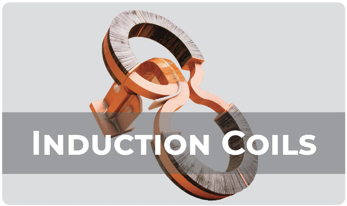
Figure 1: Induction Coil
Decoding Induction Coils
An induction coil works by storing energy in the form of a magnetic field, enabling the smooth transition of energy between electric currents and magnetic fields. This process is suitable for its ability to resist sudden changes in current flow. When the current tries to change quickly, the coil generates an opposing electromotive force (EMF) to stabilize it. This behavior is guided by the principle that the EMF works against the voltage causing the current, helping to smooth out rapid fluctuations. Mathematically, this is described by the formula e=-L (d∅)/dt, where L represents the coil's inductance, and (d∅)/dtis the rate at which the magnetic flux changes.
This property of the induction coil is used for controlling current changes in electrical circuits. It is widely used in everything from basic power supply filters to more sophisticated systems like telecommunications equipment, where precise tuning and signal processing are desired. The ability to moderate electromagnetic interactions makes the induction coil a key component in many electronic devices.
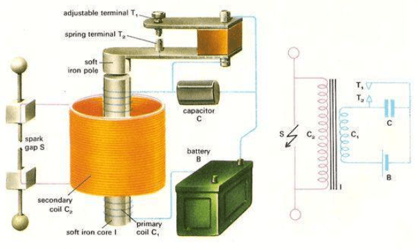
Figure 2: Components of an Induction Coil
Components of an Induction Coil
An induction coil plays a key role in electromagnetic engineering, illustrating ultimate principles through its blend of simplicity and complexity. Building an induction coil involves tightly winding insulated wire around a core, significantly impacting the coil's performance. The core can be made from air or magnetic materials like ferrite or iron. The choice of material affects the coil’s magnetic flux and overall inductance, determining how efficiently the coil operates.
Insulating the wire is dynamic. Without proper insulation, if the wires touch each other, short circuits can occur. These shorts disrupt the coil’s function by changing its inductance and can lead to serious system failures. In practical settings, the insulation on the wire can deteriorate over time due to excessive heat or unexpected voltage surges. When this happens, maintenance is often required, which may involve carefully rewinding the coil or, in severe cases, replacing it entirely.
These operational issues are not exclusive to induction coils. Transformers, which share similar designs, can also suffer from overheating, causing short circuits in the electrical mains. In worst-case scenarios, this could lead to fires in devices connected to the system. Such risks highlight the standing of careful design, material selection, and quality control during the manufacturing process. Ensuring the coil is built to withstand potential stressors significantly increases its reliability and safety.
Basic Parameters That Define Induction Coils
The performance of an induction coil depends largely on two key parameters: inductance and resonant frequency. Inductance measures the coil's ability to store magnetic energy, and it's influenced by factors such as the number of wire turns and the type of core material used. More turns or a core made from materials with high magnetic permeability, like iron or ferrite, result in higher inductance, allowing the coil to generate a stronger magnetic field for a given amount of current. Conversely, using an air core lowers the inductance but is preferred in some high-frequency applications due to reduced energy losses.
The resonant frequency is equally a must. It marks the point where the coil transitions from primarily inductive behavior to capacitive behavior, with its impedance reaching a peak. This frequency is especially high in applications like RF tuning and signal processing, where precision in controlling electromagnetic waves is suitable. Engineers need to calculate this frequency carefully to ensure the coil performs optimally in specific circuits, particularly where signal clarity or power transfer efficiency is inconsistent.
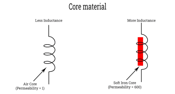
Figure 3: Core Material on Induction Coil
Core Materials and Their Magnetic Properties
Choosing the right core material is noteworthy to optimizing an induction coil's performance because it directly impacts the coil's ability to generate and maintain a magnetic field. This ability is measured by the material's magnetic permeability, which indicates how easily the material allows the formation of a magnetic field compared to a vacuum. Core materials generally fall into three categories based on their magnetic properties: paramagnetic, diamagnetic, and ferromagnetic.
Ferromagnetic materials are most commonly used in induction coils due to their high magnetic permeability. These materials significantly boost the coil's inductance, making them highly efficient for generating strong magnetic fields. As a result, ferromagnetic cores are ideal for applications like transformers, motors, and electromagnetic relays where strong magnetic fields are beneficial.
Challenges with Imperfect Induction Coils
In real-world applications, the performance of an induction coil often differs from theoretical predictions due to imperfections in design and materials. One major factor is the resistance of the winding wire, which causes heat to build up during operation. This heat reduces the coil's overall efficiency by wasting energy that could otherwise be used for its electromagnetic function. In addition, the wire's layout creates parasitic capacitance, which alters the coil’s electrical properties, affecting its frequency response and efficiency.
Categorizing Power Loss in Induction Coils
When working with induction coils, engineers focus on reducing three main types of power losses: resistive losses, core losses, and magnetic flux losses. Each affects coil performance in different ways, requiring specific strategies to address them effectively.
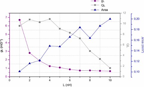
Figure 4: Resistive Losses
Resistive losses come from the inherent resistance in the coil's winding wire. In high-current applications, this resistance generates heat, which lowers the coil's efficiency and can damage the wire insulation and core over time. This heat buildup can eventually lead to coil failure if not properly managed. To reduce resistive losses, engineers often use wires with better conductivity, like copper or silver, and implement cooling systems—such as fans or heat sinks—to dissipate the heat more effectively.
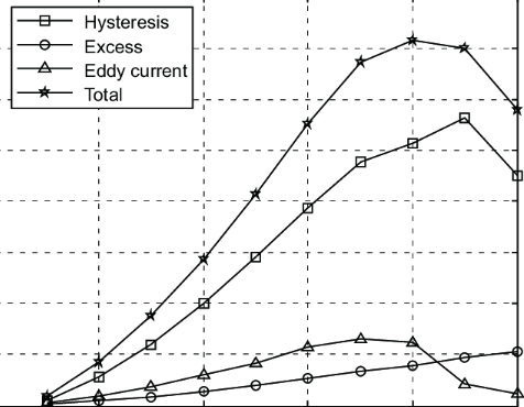
Figure 5: Core Losses
Core losses are linked to the magnetic behavior of the core material and become more noticeable at higher frequencies and lower currents. These losses consist of hysteresis losses (caused by the energy used to magnetize and demagnetize the core) and eddy current losses (induced circulating currents within the core). Engineers can reduce core losses by selecting materials with low hysteresis loss, such as soft magnetic materials, and by designing the core to limit eddy currents. This is often achieved by using laminated cores or specialized alloys that restrict unwanted current flow.
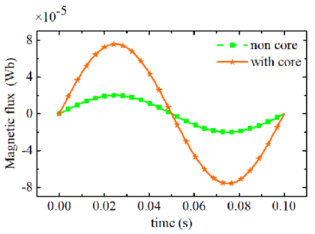
Figure 6: Magnetic Flux Losses
Magnetic flux losses occur when the magnetic field generated by the coil escapes the intended path, reducing the coil's efficiency. This is particularly problematic in applications requiring precise magnetic control. To address this, engineers can improve the coil's design by adding magnetic shielding, selecting materials that better confine the magnetic flux, or adjusting the geometry of the coil and core to keep the magnetic field focused within the desired area.
Induction Coils in Electronics
Induction coils play a main role in enhancing the functionality of electronic systems by efficiently managing electromagnetic fields. In many circuits, induction coils are used to control the flow of current. One of their unique functions is the ability to block direct current (DC) while allowing alternating current (AC) to pass through. This capability is particularly useful in power supply systems, where precise current control is fit for stable and safe operation. Capacitors, in contrast, cannot achieve this same level of control.
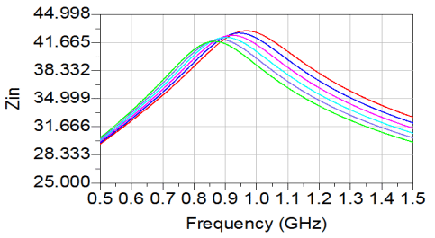
Figure 7: Frequency Tuning
In radio frequency (RF) systems, induction coils are basic for tuning circuits. They work in combination with capacitors in oscillators to set oscillation frequencies, which is dangerous for accurate signal transmission and reception in devices like radio transmitters and receivers. This tuning function ensures effective communication by maintaining signal clarity and fidelity during transmission.
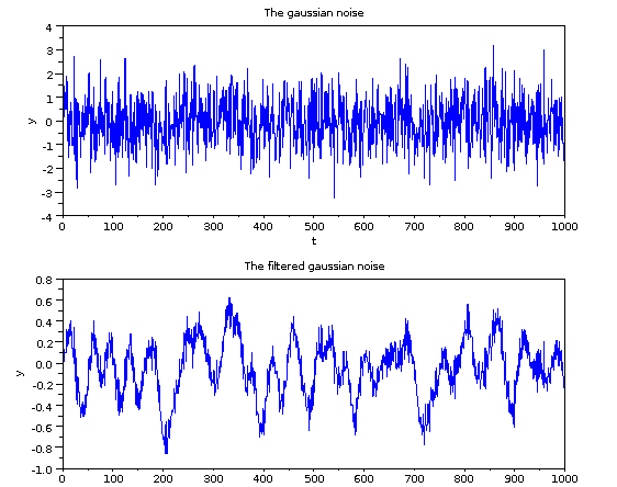
Figure 8: Signal Filtering
Induction coils are also key components in signal-filtering circuits, where they help reduce noise and modify signal bandwidth. This is especially substantial in communication devices, where clear audio transmission is required, and in precision instruments, where accurate signal processing is dynamic. By smoothing out electrical signals, coils contribute to more reliable and stable output across a range of electronic applications.
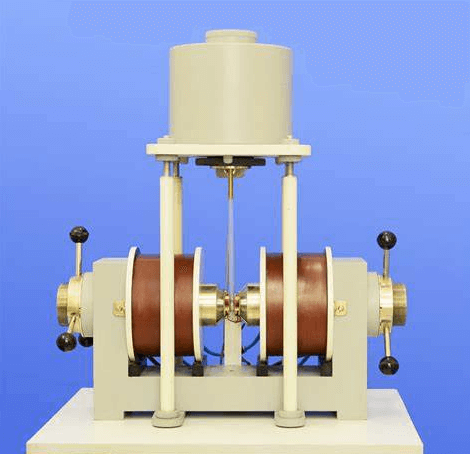
Figure 9: Vibrating Sample Magnetometer (VSM)
The versatility of induction coils extends into scientific research, particularly in instruments like the vibrating sample magnetometer (VSM). In a VSM, an induction coil surrounds a vibrating sample within a magnetic field. As the sample moves, the coil detects the induced voltages, allowing for precise measurement of the material's magnetic properties. This demonstrates the coil's major role in high-precision measurements required in scientific research.

Figure 10: Automotive Industry
In the automotive sector, induction coils are as dangerous as ignition coils in internal combustion engines. These coils transform the car battery's low voltage into the high voltage needed to ignite the fuel-air mixture in the engine’s spark plugs. The performance of ignition coils is directly tied to engine efficiency and smooth vehicle operation, making them dynamic components in modern automotive engineering.
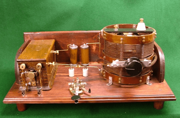
Figure 11: Spark Gap Radio Transmitters
Induction coils are also used in spark gap radio transmitters to generate the high voltages required for transmitting radio waves over long distances. This ability is suitable for maintaining strong, clear communication signals, particularly in applications where long-range transmission is required without significant signal degradation.
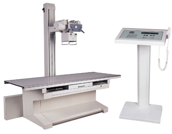
Figure 12: X-ray Machines
In the medical field, induction coils are main to the operation of X-ray machines. These coils help generate the high voltages needed to produce X-rays, which are useful for diagnostic imaging. By precisely managing voltage, induction coils ensure that X-ray machines function safely and efficiently, enabling accurate and effective diagnostic procedures in healthcare.
Conclusion
Induction coils, through their dynamic functionalities and versatile applications, stand as key components in the realm of electronic engineering. The exploration of these coils reveals a complex landscape where material science, electrical design, and operational management converge to optimize performance and enhance system reliability.
This article has highlighted the serious aspects of induction coils, including their dependency on core material choice, the intricacies of managing power losses, and their integration into various electronic systems. The insights into managing real-world operational challenges and the iterative process of testing and refinement underscore the necessity for a deep understanding of both theoretical and practical aspects of coil design. Ultimately, the induction coil's capacity to control electromagnetic fields not only underscores its utility in a vast range of applications but also reaffirms the need for continuous innovation and meticulous design in the ever-evolving field of electronic systems.
Frequently Asked Questions [FAQ]
1. What is a coil used for in electronics?
Coils in electronics, often called inductors, are primarily used for their ability to store energy in a magnetic field when current flows through them. This property makes them insistent in circuits that require energy storage, filtering, or timing functions. For instance, in power supplies, coils smooth out fluctuations to provide a stable output voltage.
2. What is the purpose of the coil in electricity?
In electrical systems, coils are used to induce a magnetic field or to be influenced by one, depending on their role. Their ability to temporarily store energy and release it helps in managing current flow, which is dynamic in transformers and relays. This capability allows coils to convert high-voltage electricity to lower voltage levels suitable for home or industrial use.
3. What is an induction coil used for?
An induction coil is a type of transformer used to generate high-voltage pulses from a low-voltage source. Historically, these have been used in early radio transmission and spark-gap radio transmitters, where they generated the required voltages to initiate a spark across a gap, thus creating radio frequency energy.
4. What is the application of electromagnetic induction in an induction coil?
The ultimate principle behind induction coils is electromagnetic induction, where a changing magnetic field within the coil generates an electric field. This process is exploited to transform voltage levels; for example, stepping up a low input voltage to a high output voltage. This high voltage is wanted for applications like X-ray generation, ignition systems in engines, and certain types of lighting including fluorescent lamps.
5. What are the applications of induction in a single coil?
A single coil, using electromagnetic induction, can function in multiple roles, such as in metal detectors where they detect metallic objects by sensing the change in magnetic field caused by metals. Another application is in electric guitars, where single coils pick up string vibrations and convert them into electrical signals, which are then amplified. These examples highlight how the operational nuances of coils adapt to the needs of various applications, each exploiting the coil’s ability to interact with magnetic fields.
About us
ALLELCO LIMITED
Read more
Quick inquiry
Please send an inquiry, we will respond immediately.
DL2032 Vs. CR2032
on September 11th
Exploring Double Balanced Mixers: Circuitry, Theory, and Practical Operation
on September 11th
Popular Posts
-

What is GND in the circuit?
on January 1th 3036
-

RJ-45 Connector Guide: RJ-45 Connector Color Codes, Wiring Schemes, R-J45 Applications, RJ-45 Datasheets
on January 1th 2607
-

Fiber Connector Types: SC Vs LC And LC Vs MTP
on January 1th 2162
-

Understanding Power Supply Voltages in Electronics VCC, VDD, VEE, VSS, and GND
on November 13th 2065
-

Comparison Between DB9 and RS232
on January 1th 1789
-

What Is An LR44 Battery?
Electricity, that ubiquitous force, quietly permeates every aspect of our daily lives, from trivial gadgets to life-threatening medical equipment, it plays a silent role. However, truly grasping this energy, especially how to store and efficiently output it, is no easy task. It is against this background that this article will focus on a type of coin cell battery that may seem insignificant on the...on January 1th 1754
-

Understanding the Fundamentals:Inductance Resistance, andCapacitance
In the intricate dance of electrical engineering, a trio of fundamental elements takes center stage: inductance, resistance, and capacitance. Each bears unique traits that dictate the dynamic rhythms of electronic circuits. Here, we embark on a journey to decipher the complexities of these components, to uncover their distinct roles and practical uses within the vast electrical orchestra. Inductan...on January 1th 1704
-

CR2430 Battery Comprehensive Guide: Specifications, Applications and Comparison to CR2032 Batteries
What is CR2430 battery ?Benefits of CR2430 BatteriesNormCR2430 Battery ApplicationsCR2430 EquivalentCR2430 VS CR2032Battery CR2430 SizeWhat to look for when buying the CR2430 and equivalentsData Sheet PDFFrequently Asked Questions Batteries are the heart of small electronic devices. Among the many types available, coin cells play a crucial role, commonly found in calculators, remote controls, and ...on January 1th 1640
-

What Is RF and Why Do We Use It?
Radio Frequency (RF) technology is a key part of modern wireless communication, enabling data transmission over long distances without physical connections. This article delves into the basics of RF, explaining how electromagnetic radiation (EMR) makes RF communication possible. We will explore the principles of EMR, the creation and control of RF signals, and their wide-ranging uses. The article ...on January 1th 1618
-
Comprehensive guide to hFE in transistors
Transistors are crucial components in modern electronic devices, enabling signal amplification and control. This article delves into the knowledge surrounding hFE, including how to select a transistor's hFE value, how to find hFE, and the gain of different types of transistors. Through our exploration of hFE, we gain a deeper understanding of how transistors work and their role in electronic circu...on November 13th 1561
