The Backbone of Electrical Systems: A Comprehensive Guide to Rectifiers
Rectification is a basic aspect of electrical engineering, good for converting alternating current (AC) to direct current (DC), which is useful for the operation of numerous electronic devices and systems. This article examines the detailed aspects of rectification, covering basic principles, various components, and the different types of rectifiers tailored for specific applications and power needs. By exploring the workings of half-wave and full-wave rectifiers, including advanced types like bridge and polyphase rectifiers, we gain insights into their capabilities, limitations, and the technological advancements that enhance their efficiency and application. The article also discusses practical uses where rectifiers are needed, ranging from telecommunications to medical devices, showcasing their widespread impact on modern technology. Highlights the role of components such as diodes and capacitors in ensuring a steady DC output from an unstable AC input, with the goal of offering an in-depth understanding of rectification technologies and their importance in everyday and specialized electrical purposes.
Catalog
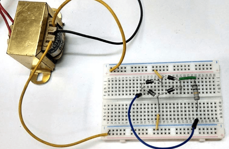
Figure 1: Rectifier Circuit
What is Rectification?
Rectification is the process of altering electric current behavior from flowing in multiple directions to flowing in only one direction. In most electronic devices, there are two types of currents: alternating current (AC) and direct current (DC). AC changes direction multiple times during a given period, while DC flows steadily in one direction. For electronic appliances and devices to receive a continuous voltage supply, AC must be converted into DC, a process known as AC rectification.
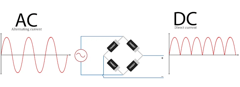
Figure 2: Schematic Diagram of Rectification
A rectifier, the component that performs this task, can take various forms, including solid-state diodes, vacuum tube diodes, mercury-arc valves, silicon-controlled rectifiers, and other silicon-based semiconductor switches. Among these, the semiconductor diode is particularly important, acting like a one-way valve for electric charge. It allows current to flow in only one direction, facilitating the conversion from AC to DC. The half-wave rectifier, a simpler form of rectification, supports more advanced rectifying systems and numerous applications that require DC power, underpinning the functionality of countless electronic devices in everyday use.
Rectifier Components
P-N Junction Diode: This device permits current to flow in only one direction. When the P side of the diode has a higher potential than the N side, it is forward biased and allows current to pass. Conversely, when the N side has a higher potential, it is reverse biased and blocks the current flow.
Alternating Current (AC): AC is an electric current that periodically changes direction.
Direct Current (DC): Unlike AC, DC is a type of electric current that flows consistently in one direction without changing periodically.
Waveform: This is a graphical representation that shows the magnitude and direction of electric current or voltage over time.
Vrms and Irms: These are the root mean square values of voltage (Vrms) and current (Irms) for AC. They are calculated as 1/√2 times the peak voltage or current, providing a measure of the effective value of the fluctuating AC.
Capacitor: A capacitor is a two-terminal device that stores energy in an electric field. It can charge and discharge within a circuit, helping to smooth out voltage fluctuations and provide a stable DC output.
Function Generator: This device generates various electrical waveforms, including AC, with specific voltages and frequencies required for testing and operating electronic circuits.
Different Types of Rectifiers
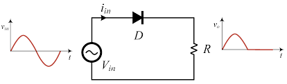
Figure 3: Uncontrolled Rectifier
Uncontrolled Rectifiers
An uncontrolled rectifier is a type of rectifier whose output voltage cannot be adjusted. There are two main kinds of uncontrolled rectifiers: half-wave rectifiers and full-wave rectifiers.
Half-wave rectifier converts only one half of the AC cycle into DC. It allows either the positive or negative half of the AC wave to pass, blocking the other half.
Full-wave rectifier converts both the positive and negative halves of the AC cycle into DC. An example of a full-wave rectifier is the bridge rectifier, which uses four diodes arranged in a Wheatstone bridge configuration to achieve this conversion.
Controlled Rectifiers
A controlled rectifier allows for the adjustment of the output voltage. Components such as Silicon Controlled Rectifiers (SCRs), Metal-Oxide-Semiconductor Field-Effect Transistors (MOSFETs), and Insulated-Gate Bipolar Transistors (IGBTs) are used to create these rectifiers. Controlled rectifiers are often preferred over uncontrolled ones due to their versatility.
Half-wave controlled rectifier is similar to the half-wave uncontrolled rectifier but replaces the diode with an SCR, enabling control over the output voltage.
Full-wave controlled rectifier converts both halves of the AC cycle into DC but allows for voltage regulation through the use of SCRs or other similar components.
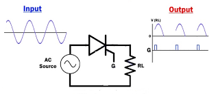
Figure 4: Controlled Rectifier
Half-Wave Rectification
Half-wave rectification, though simple in design, has notable limitations, especially when high efficiency and low harmonic distortion are required. This method only processes one half of the AC waveform, ignoring the other half. As a result, it creates inefficiencies and introduces high harmonic content in the output, complicating smoothing operations.
This type of rectification is typically used in less demanding applications. For instance, it's suitable for certain lighting dimmers that do not need a continuous power supply. In these dimmers, switches alternate between full AC power for maximum brightness and a half-wave rectified output for dimming. This technique pulses power to the lamp, preventing the filament from rapid temperature changes. This gradual heating and cooling maintain a consistent, dimmed light output and minimize flickering, effectively managing energy flow to slower-responding loads.
Despite its basic operation, half-wave rectification can be energy-efficient in specific scenarios where advanced power control and continuous output are not desired. This approach highlights the practical use of half-wave rectifiers in applications that benefit from simple, yet effective, power modulation.
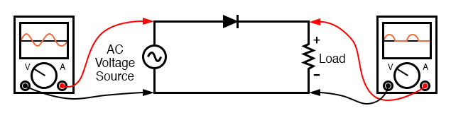
Figure 5: Half-Wave Rectifier Circuit
Positive Half-Cycle in Half Wave Rectification
During the positive half-cycle of an AC input, the diode becomes forward-biased and functions as a short circuit. This allows current to flow through the circuit, resulting in the AC input being replicated in the DC output. However, in practical applications, the output voltage is slightly lower than the input voltage due to the voltage drop across the diode.

Figure 6: Positive Half Wave Rectifier
Negative Half-Cycle in Half Wave Rectification
During the negative half-cycle of the AC input, the diode is reverse-biased and behaves like an open circuit. As a result, no current flows through the circuit during this period, and the output does not include the negative half-cycle of the input.
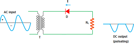
Figure 7: Negative Half Wave Rectifier
Advantages and Disadvantages of Half Wave Rectifier
Half-wave rectifiers offer several advantages, making them suitable for certain applications. One of the main benefits is their simplicity; the circuit is straightforward and easy to implement. This simplicity translates into low-cost designs, as the components required are inexpensive. Additionally, the uncomplicated design of half-wave rectifiers allows for easy and large-scale manufacturing.
However, half-wave rectifiers also have notable disadvantages. A serious drawback is the high ripple factor. This causes substantial fluctuations in the DC output voltage, which can be problematic in many applications. Half-wave rectifiers suffer from high power loss because they only utilize one half of the input waveform. This results in considerable power dissipation and reduced efficiency. Compared to full-wave rectifiers, half-wave rectifiers are less efficient overall, as they make use of only half of the input cycle. Furthermore, the output voltage of a half-wave rectifier is lower than that of a full-wave rectifier, limiting its applicability in systems that require higher voltages.
Full-Wave Rectifiers
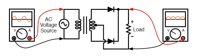
Figure 8: Full-Wave Rectifier
Full-wave rectifiers improve rectification by using the entire AC waveform, enhancing conversion efficiency. Unlike half-wave rectifiers, which only use one half of the AC cycle, full-wave rectifiers convert both halves into DC. This process effectively doubles the power output. A common design for full-wave rectifiers is the center-tap configuration. This setup uses a transformer with a center-tapped secondary winding and two diodes. The center-tap rectifier operates by alternating between the two diodes based on the AC polarity. Each diode conducts in turn, ensuring both halves of the AC waveform are used. This method provides a continuous and more stable DC output, increasing the output voltage and reducing ripple frequency. The resulting DC is smoother than that from half-wave rectifiers. Full-wave rectifiers are important for situations that need a steady and reliable DC supply, like power supplies for electronic gadgets. By using the entire AC input, full-wave rectifiers offer a strong solution for demanding tasks, providing consistent DC power.
Positive Half-Cycle in Full-Wave Rectification
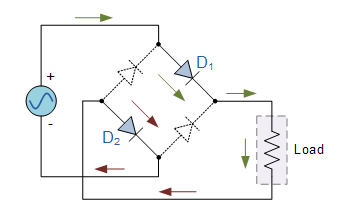
Figure 9: Positive Full Wave Rectifier
A consistent DC output in full-wave rectification with a center-tap design depends on the circuit's behavior during the positive half-cycle. When the AC source shows a positive voltage, the upper diode becomes forward-biased, allowing current to flow through the upper half of the transformer's secondary winding. This process directs the positive half of the AC waveform to the load.
The operation of the upper diode during this phase is valuable. It conducts the positive voltage to the load while blocking negative voltage components. This selective conduction ensures that the positive segment of the waveform is efficiently converted into DC without interference from the negative half. Maintaining a steady and dependable DC supply involves carrying out this action.
By focusing on the positive half of the AC cycle, the center-tap full-wave rectifier maximizes the usable energy from the AC source. This detailed look at the positive half-cycle's role in the rectifier circuit highlights its importance in converting AC to DC power efficiently and stably, ensuring a high-quality and consistent DC output.
Negative Half-Cycle in Full-Wave Rectification
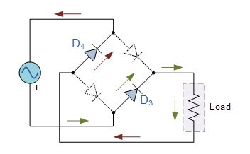
Figure 10: Negative Full Wave Rectifier
In the negative half-cycle of a center-tap full-wave rectifier, the circuit's operation shifts to maintain continuous power delivery. When the AC polarity reverses, the bottom diode becomes forward-biased and conducts, engaging the lower half of the transformer's secondary winding. This process converts the negative half of the AC waveform into a positive output, just like during the positive half-cycle.
The alternating conduction between the upper and lower diodes is key to full-wave rectification. It ensures a continuous and stable DC supply by utilizing both halves of the AC waveform. For devices that require constant DC power, this dual conduction not only increases power conversion efficiency but also stabilizes the output by preserving consistent polarity and amplitude.
The precise coordination of diode activity during each half-cycle maximizes the AC input's potential, reducing waste and enhancing output efficiency. Analyzing the negative half-cycle demonstrates how full-wave rectification adapts dynamically to changing input conditions, providing a reliable and uninterrupted DC supply. This method shows its superiority over simpler rectification techniques by effectively managing complex power demands.
Disadvantages of Full-Wave Rectifier Design
Full-wave rectifiers are more efficient than half-wave rectifiers, but they have drawbacks that affect their use. One major issue is the need for a transformer with a center-tapped secondary winding. This requirement is especially problematic in high-power applications where transformers must be durable and capable of handling large power loads without notable losses.
These high-power transformers are costly and physically large. The increased size and expense make full-wave rectifiers less practical in applications where space is limited or budget constraints are tight. The bulkiness and cost hinder their use in portable or small-scale devices where compactness and affordability are required. They influence decisions on when and where to use full-wave rectification. Despite their efficiency and output stability, these practical constraints require a careful evaluation of the intended application, power needs, and overall system design.
Versatility in Full-Wave Rectifier Configurations
The full-wave center-tap rectifier design is highly versatile, allowing for modifications such as reversing the load polarity. This can be done by changing the orientation of the diodes or integrating them in parallel with an existing positive-output rectifier. This flexibility to generate both positive and negative voltages from a single power source demonstrates the adaptability of full-wave rectifiers. This design flexibility ensures these rectifiers can be customized to meet specific electrical needs, enhancing their use in complex circuits. This is particularly helpful for applications that need different voltage polarities, like bipolar transistor amplifiers or operational amplifier systems, where having two supply voltages is recommended.
The ability to modify and extend the functionality of full-wave rectifiers beyond basic rectification highlights their importance in advanced electronic design. This adaptability not only increases the utility of full-wave rectifiers but also encourages innovation and efficiency in developing electronic systems, meeting a wide range of technical requirements and application scenarios.
Bridge Rectifiers
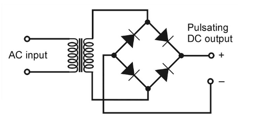
Figure 11: Bridge Rectifiers
Among the rectifiers, the bridge rectifier is the most efficient rectifier circuit. We can define bridge rectifiers as a type of full-wave rectifier that uses four or more diodes in a bridge circuit configuration to efficiently convert alternating (AC) current to a direct (DC) current.
The full-wave bridge rectifier is often preferred over the center-tap design for its reliability and efficient polarity management. It uses four diodes in a bridge configuration to maintain a consistent output polarity, regardless of input polarity. This design converts the entire AC waveform into a stable DC output, making it highly reliable for various electronic applications.
A strength of the bridge rectifier is its ability to keep the current flow through the load continuous, even as the AC source's polarity changes. However, the bridge configuration does have drawbacks. Each of the four diodes introduces a voltage drop, typically around 0.7 volts per diode, which can significantly reduce the output voltage.
Despite these voltage drops, the advantages of the full-wave bridge rectifier often outweigh its disadvantages, especially in higher voltage applications where the diode voltage drops are less relative to the overall voltage. Its ability to provide a reliable and stable DC output under varying input conditions underscores its superiority, making it a best component in many modern electronic systems.
Full-Wave Bridge Rectifier Circuit Diagram
Visual aids can remarkably enhance comprehension for those new to electronics. An alternative circuit diagram of the full-wave bridge rectifier, designed with educational purposes in mind, can be very helpful. This version of the diagram arranges all diodes horizontally, simplifying the visualization of the circuit's flow. This layout clarifies each diode's function within the rectifier and making the principles of bridge rectification more accessible.

Figure 12: Full-Wave Bridge Rectifier
The horizontal arrangement of diodes helps users clearly observe how current flows through the circuit during both halves of the AC cycle. This setup simplifies the process of converting AC to DC using a bridge rectifier. By displaying the components and their connections in a clear manner, it becomes easier to understand how each part ensures the continuity and stability of the output current.
Polyphase Bridge Rectifiers
Adapting bridge rectifiers for polyphase AC systems enhances their utility, especially in high-power applications. By connecting each phase of the polyphase system to the rectifier with a dedicated pair of diodes, the circuit efficiently distributes power across both positive and negative loads. This setup reduces the amount of AC content in the final DC output, which is important in industrial applications, by utilizing the inherent phase changes in polyphase systems.
The phase-shifted pulses from multiple AC sources overlap, resulting in a much smoother DC output. This smoothness is a must for applications that require high electrical stability and minimal ripple, such as sensitive electronic equipment or large industrial machinery. By reducing the ripple effect typical in single-phase rectifiers, the polyphase bridge rectifier not only improves the quality and efficiency of the DC output but also enhances the overall reliability and performance of the power supply system.
Advantages and Disadvantages of Polyphase Bridge Rectifiers
Advantages
Bridge rectifiers are more efficient than half-wave rectifiers. The DC output of a bridge rectifier is smoother compared to a half-wave rectifier because it utilizes both the positive and negative half cycles of the AC signal.
Polyphase rectifiers use multiple AC sources with overlapping phase-shifted pulses, resulting in a smoother DC output than single-phase rectifiers. Polyphase rectifiers minimize voltage and current fluctuations (ripple), providing higher electrical stability, good for precision instruments and medical equipment.
The smoother DC output from polyphase rectifiers reduces stress on electrical components, enhancing performance and reducing maintenance needs. Reduced ripple effects lead to a more reliable power supply system.
The efficiency of polyphase rectifiers lowers the need for additional filtering and stabilization circuits, reducing energy consumption and maintenance costs. Over time, this leads to savings, especially in industrial settings.
Disadvantages
Bridge rectifiers have a more complex circuit compared to half-wave and center-tapped full-wave rectifiers, using four diodes instead of two.
The use of more diodes in bridge rectifiers results in higher power loss. While a center-tapped full-wave rectifier uses one diode per half cycle, a bridge rectifier uses two diodes in series per half cycle, leading to a higher voltage drop.
Reducing Ripple Voltage in Rectified Outputs
Ripple voltage, the residual AC within a DC output, poses a challenge in rectification. This fluctuation can negatively impact electronic devices that need a stable DC power supply. Therefore, managing and minimizing ripple voltage is needed in high-precision electronic applications.
To reduce ripple, filtering networks are often used. These networks typically combine capacitors and inductors to smooth out voltage oscillations. Capacitors store charge and release it during voltage drops, stabilizing the output. Inductors help by restricting the rate of current change, further smoothing the voltage curve. The effectiveness of these filters depends on the power levels involved. For systems with lower power requirements, simple capacitor filters may suffice. However, higher power or more sensitive applications may need more complex filtering arrangements. Controlling ripple voltage is required as it directly affects the reliability, efficiency, and stability of electronic systems. A smoother DC output allows electronic devices to operate optimally, free from disruptive interference caused by excessive ripple.
Classifying Rectifiers by Pulse Numbers, Way and Phase
Rectifier circuits are categorized by phase, way, and pulse characteristics.
Pulse Characteristic
The "pulse" characteristic indicates the number of DC output pulses generated per AC cycle. More pulses per cycle result in a smoother and more stable DC output. For example, a 1-pulse rectifier offers basic functionality, while a 6-pulse rectifier provides a much smoother output, suitable for sensitive and high-demand applications.
Way Characteristic
The "way" characteristic describes how the AC is converted into DC, either in a single-way (half-wave) or two-way (full-wave) fashion.
Single-way rectifiers are simple but limited in efficiency and output quality. They rectify only one half of the AC cycle, resulting in power loss and a highly fluctuating DC output.
Two-way rectifiers rectify both the positive and negative halves of the waveform, improving power conversion efficiency and enhancing the smoothness of the DC output.
Phase Characteristic
The "phase" characteristic refers to the number of AC inputs used in the rectifier. Rectifiers can be either single-phase or three-phase.
Single-phase rectifiers are typically used for lower power demands. A single-phase half-wave rectifier allows only one half of the AC waveform to pass through, blocking the other half, resulting in a single pulse per AC cycle, which makes it a 1-pulse unit. However, the single-pulse output is less smooth and more pulsatile, which might not be suitable for applications requiring stable DC output.
A single-phase full-wave rectifier, in contrast, allows both halves of the AC waveform to pass, converting them into a pulsating DC output with two pulses per cycle, making it a 2-pulse unit. This arrangement improves the smoothness and efficiency of the DC output, making it suitable for a broader range of applications compared to its half-wave counterpart.
Three-phase rectifiers are used in more demanding environments, such as industrial equipment and high-power applications. A three-phase full-wave rectifier utilizes the phase shifts inherent in a three-phase system to produce six pulses per AC cycle, classifying it as a 6-pulse unit. This design yields a much smoother and more efficient output, which is particularly beneficial for applications requiring consistent, high-quality power delivery.
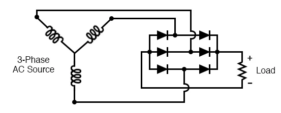
Figure 13: Three-Phase Rectifier Circuit
Advances in Polyphase Rectifier System
In advanced polyphase rectifier systems, generating a pulse count greater than twice the number of phases is achievable through innovative transformer configurations and strategic paralleling of rectifier outputs. By skillfully leveraging phase shifts, engineers can reduce ripple effects, thereby enhancing the DC output's overall quality.
These sophisticated designs are particularly beneficial in high-power applications where reducing ripple is important, but space for extensive filtering components is limited. Increasing the number of pulses smooths the DC output and improves the power system's efficiency and reliability, making it ideal for demanding environments requiring robust and consistent electrical performance.
This advancement in polyphase rectifier technology marks a particular step in meeting complex electrical requirements while managing physical and economic constraints. The strategic increase in pulse numbers through advanced circuit configurations not only optimizes rectifier systems but also highlights the importance of continuous innovation in electrical engineering to address and overcome contemporary challenges.
Applications and Uses of Rectifiers
Televisions, Radios, and Computers: These common household electronics depend on rectifiers for stable DC power, even though they are typically plugged into AC outlets. Rectifiers are used for signal detection to ensure proper radio functioning.
Phone Chargers: Rectifiers convert AC from wall outlets into the DC needed to charge mobile devices.
Machinery and Control Systems: Industrial machines and automated processes rely on rectifiers for consistent DC power.
Telecommunications: Equipment like cell towers and data centers depend on rectifiers to maintain stable power supplies.
Welding Equipment: Ensures that welding machinery operates with the require DC power for precision work. They supply polarized voltage good for the welding process.
Electric Vehicles (EVs) and Railways: Rectifiers convert AC from charging stations or overhead lines into usable DC power for propulsion systems.
Solar Inverters: These devices use rectifiers to transform DC generated by solar panels into AC, which is suitable for home and grid use.
Medical Devices: MRI machines and X-ray generators rely on rectifiers for accurate DC power.
Aviation Systems: They convert power for avionics, lighting, and other onboard systems.
Radar Systems: Rectifiers are used for both power supply and signal processing.
Conclusion
Rectification matters to many different types of electrical systems and devices operating at optimal efficiency. From simple half-wave rectifiers used in household dimmers to complex polyphase bridge rectifiers in industrial machinery, each type play’s role in converting AC to usable DC power. We explored the technical details and operational principles of various rectifier types, emphasizing their benefits and limitations. By examining the functions of different components and circuit designs, we recognize the rectifier's role in stabilizing power supply and improving device performance. Ongoing advancements in rectifier technology, especially in polyphase systems, highlight a dynamic field aimed at meeting growing power demands while addressing efficiency and space challenges. The integration of rectifiers in diverse applications, from consumer electronics to medical systems, underscores their different role in modern technology. This article anticipates future developments, providing professionals and enthusiasts with the knowledge to innovate in an increasingly electrified world.
Frequently Asked Questions [FAQ]
1. What is the working principle of rectifier?
A rectifier primarily functions to convert alternating current (AC) into direct current (DC). This process is fundamental in various electrical applications where DC power is needed, such as charging batteries, operating DC motors, and powering electronic circuits. The rectifier achieves this through the use of semiconductor devices like diodes, which allow current to flow in only one direction. Eventually, the diodes block part of the AC signal (either the positive or negative half of the waveform) or modify both halves to flow in a single direction, thereby producing DC.
2. How does a rectifier convert AC to DC?
The conversion of AC to DC is executed by allowing the AC voltage to pass through one or more diodes arranged in specific configurations—such as half-wave, full-wave, and bridge rectifiers. In a half-wave rectifier, only one half of the AC waveform is allowed to pass through, effectively blocking the other half. A full-wave rectifier, on the other hand, uses multiple diodes to invert the negative half of the AC waveform into positive, enabling the entire waveform to contribute to the output. Bridge rectifiers, using four diodes arranged in a bridge configuration, enhance this process by allowing both halves of the AC input to be utilized, resulting in a more consistent and higher voltage DC output.
3. What is the main function of rectifier circuit?
The main function of a rectifier circuit is to produce a steady DC output from an AC input. This is required in applications where stable DC power is required. Beyond just converting AC to DC, rectifiers also help in smoothing the output using components like capacitors and inductors, which reduce the ripple in the output current, making it more uniform.
4. What causes a rectifier to fail?
Rectifier failures can arise from several factors, such as thermal stress, electrical overload, and component wear. Overheating caused by excessive current flow or poor cooling can damage the semiconductor material in diodes. Electrical surges can exceed the voltage tolerance of the diodes, leading to breakdown. Similarly, prolonged use can wear out the diodes and associated components, reducing their efficiency and lifespan.
5. What is an example of a rectifier?
A common example of a rectifier is the bridge rectifier used in household power supplies. This type of rectifier converts the AC input from the mains power supply into a DC output, which is then used to charge devices like laptops and mobile phones, demonstrating its practical application in everyday electronic devices.
6. What is the best rectifier circuit?
The "best" rectifier circuit depends on the specific requirements of the application, including factors like the desired efficiency, cost, and complexity. Generally, bridge rectifiers are considered superior for most standard applications because they efficiently utilize both halves of the AC waveform, resulting in a higher output voltage and less ripple compared to half-wave and full-wave rectifiers. For high-precision applications, complex multi-stage rectifier circuits with additional smoothing and regulation stages might be used to ensure a highly stable DC output.
About us
ALLELCO LIMITED
Read more
Quick inquiry
Please send an inquiry, we will respond immediately.
Understanding the Power of the S-R Latch: A Gateway to Modern Electronics
on June 19th
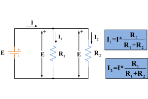
Current Divider Circuits and Effective Use of the Divider Formula
on June 14th
Popular Posts
-

What is GND in the circuit?
on January 1th 2937
-

RJ-45 Connector Guide: RJ-45 Connector Color Codes, Wiring Schemes, R-J45 Applications, RJ-45 Datasheets
on January 1th 2497
-

Fiber Connector Types: SC Vs LC And LC Vs MTP
on January 1th 2088
-

Understanding Power Supply Voltages in Electronics VCC, VDD, VEE, VSS, and GND
on November 9th 1887
-

Comparison Between DB9 and RS232
on January 1th 1759
-

What Is An LR44 Battery?
Electricity, that ubiquitous force, quietly permeates every aspect of our daily lives, from trivial gadgets to life-threatening medical equipment, it plays a silent role. However, truly grasping this energy, especially how to store and efficiently output it, is no easy task. It is against this background that this article will focus on a type of coin cell battery that may seem insignificant on the...on January 1th 1712
-

Understanding the Fundamentals:Inductance Resistance, andCapacitance
In the intricate dance of electrical engineering, a trio of fundamental elements takes center stage: inductance, resistance, and capacitance. Each bears unique traits that dictate the dynamic rhythms of electronic circuits. Here, we embark on a journey to decipher the complexities of these components, to uncover their distinct roles and practical uses within the vast electrical orchestra. Inductan...on January 1th 1651
-

CR2430 Battery Comprehensive Guide: Specifications, Applications and Comparison to CR2032 Batteries
What is CR2430 battery ?Benefits of CR2430 BatteriesNormCR2430 Battery ApplicationsCR2430 EquivalentCR2430 VS CR2032Battery CR2430 SizeWhat to look for when buying the CR2430 and equivalentsData Sheet PDFFrequently Asked Questions Batteries are the heart of small electronic devices. Among the many types available, coin cells play a crucial role, commonly found in calculators, remote controls, and ...on January 1th 1541
-

What Is RF and Why Do We Use It?
Radio Frequency (RF) technology is a key part of modern wireless communication, enabling data transmission over long distances without physical connections. This article delves into the basics of RF, explaining how electromagnetic radiation (EMR) makes RF communication possible. We will explore the principles of EMR, the creation and control of RF signals, and their wide-ranging uses. The article ...on January 1th 1537
-

CR2450 vs CR2032: Can The Battery Be Used Instead?
Lithium manganese batteries do have some similarities with other lithium batteries. High energy density and long service life are the characteristics they have in common. This kind of battery has won the trust and favor of many consumers because of its unique safety. Expensive tech gadgets? Small appliances in our homes? Look around and you'll see them everywhere. Among these many lithium-manganes...on January 1th 1504
HOT Part Number
-

CSD17304Q3
Texas Instruments
MOSFET N-CH 30V 15A/56A 8VSON
UC3846DWTR
Texas Instruments
IC REG CTRLR MULT TOP 16SOIC
MIC2937A-5.0WU
Microchip Technology
IC REG LINEAR 5V 750MA TO263-3
0441002.WRA
Littelfuse Inc.
FUSE 2.0A 32V SMD 0603
MC9S08QD2MSC
NXP USA Inc.
IC MCU 8BIT 2KB FLASH 8SOIC
STTA112U
STMicroelectronics
DIODE GEN PURP 1.2KV 1A SMB
STTH8S06FP
STMicroelectronics
DIODE GEN PURP 600V 8A TO220FPAC
GRM0335C1H5R2BA01D
Murata Electronics
CAP CER 5.2PF 50V C0G/NP0 0201
RO3132A
Murata Electronics
SAW RES 312.0000MHZ SMD
LQP03TG2N1B02D
Murata Electronics
FIXED IND 2.1NH 450MA 250MOHM SM
12067C103KAJ2A
KYOCERA AVX
CAP CER 10000PF 500V X7R 1206
LTC4231CMS-1#PBF
Analog Devices Inc.
IC HOT SWAP CTRLR GP 12MSOP
NLV32T-1R0J-EF
TDK Corporation
FIXED IND 1UH 400MA 700 MOHM SMD
DS28E10R-W15+1T
Analog Devices Inc./Maxim Integrated
IC EPROM 224BIT 1-WIRE SOT23-3
STM32F446ZEH6TR
STMicroelectronics
IC MCU 32BIT 512KB FLSH 144UFBGA
R5F51138ADFM#3A
Renesas Electronics America Inc
IC MCU 32BIT 512KB FLASH 64LFQFP
MCP4462-104E/ST
Microchip Technology
IC DGT POT 100KOHM 257TP 14TSSOP
MK64FX512VLL12
NXP USA Inc.
IC MCU 32BIT 512KB FLASH 100LQFP -

BQ24725ARGRR
Texas Instruments
IC BATT CHG LI-ION 1-4CEL 20VQFN
GRM0335C1H1R0CD01J
Murata Electronics
CAP CER 1PF 50V C0G/NP0 0201
EP3C10E144C7N
Intel
IC FPGA 94 I/O 144EQFP
FMMT494TA
Diodes Incorporated
TRANS NPN 120V 1A SOT23-3
AD7891AP-1
Analog Devices Inc.
IC DAS 12BIT 500K 44PLCC
DB106-G
Comchip Technology
BRIDGE RECT 1PHASE 800V 1A DB
HMC617LP3ETR
Analog Devices Inc.
IC AMP GPS 550MHZ-1.2GHZ 16QFN
CL21B105KAFNNNE
Samsung Electro-Mechanics America, Inc.
CAP CER 1UF 25V X7R 0805
CY7C421-10VC
Cypress Semiconductor Corp
FIFO, 512X9, 10NS, ASYNCHRONOUS
PCMB053T-R68MS
Susumu
FIXED IND 680NH 8.5A 12 MOHM SMD
AOZ1320CI-07
Alpha & Omega Semiconductor Inc.
IC LOAD SWITCH SOT23-6
AD6657ABBCZ
Analog Devices Inc.
IC QUAD IF RECEIVER 144BGA
NCP502SQ33T1G
onsemi
IC REG LINEAR 3.3V 80MA SC88A
B350AF-13
Diodes Incorporated
DIODE SCHOTTKY 50V 3A SMAF
NUF2042XV6T1G
onsemi
FILTER RC(PI) 22 OHM/42PF SMD
10042867-50MB10ELF
Amphenol ICC (FCI)
CONN FPC BOTTOM 50POS 0.5MM R/A
FMS6246MTC20X
Fairchild Semiconductor
CONSUMER CIRCUIT, PDSO20
TCET1109
Vishay Semiconductor Opto Division
OPTOISOLATR 5KV TRANSISTOR 4-DIP -
IR3870MTRPBF
Infineon Technologies
IC REG BUCK ADJUSTABLE 10A PQFN
SN74AHC139DGVR
Texas Instruments
IC DECODER/DEMUX 1X2:4 16TVSOP
C2012X7R1C684M125AA
TDK Corporation
CAP CER 0.68UF 16V X7R 0805
LMX2370TMX
Texas Instruments
IC PLL FREQ SYNTH 20TSSOP
1N3347A
Solid State Inc.
DO5 50 WATT ZENER DIODES
EP4CGX110CF23I7N
Intel
IC FPGA 270 I/O 484FBGA
IDT723612L20PQF
Renesas Electronics America Inc
IC FIFO 64X36X2 20NS 132QFP
18121C155KAZ2A
KYOCERA AVX
CAP CER 1.5UF 100V X7R 1812
MAX4304ESA
Analog Devices Inc./Maxim Integrated
IC VOLTAGE FEEDBACK 1 CIRC 8SOIC
GRM0335C1E300GD01D
Murata Electronics
CAP CER 30PF 25V C0G/NP0 0201
1N3296A
Powerex Inc.
DIODE GP 1.2KV 100A DO205AA
1718250100
Molex
TERM BLADE FEMALE 10-12AWG TIN
SK315B
SMC Diode Solutions
DIODE SCHOTTKY 150V 3A SMB
LM2618BTL
Texas Instruments
IC REG BUCK PROG 300MA 10USMD
MT58L64L18CT-10
Micron Technology Inc.
CACHE SRAM, 64KX18, 5NS
ISL9219IRZ-T
Renesas Electronics America Inc
IC BATT CHG LI-ION 1CELL 20QFN
MAX662ACSA+
Analog Devices Inc./Maxim Integrated
IC REG CHARG PUMP 12V 30MA 8SOIC
0448010.MR
Littelfuse Inc.
FUSE BRD MNT 10A 125VAC/VDC SMD