Current Divider Circuits and Effective Use of the Divider Formula
The exploration of electrical circuits, particularly the dynamics of current and voltage distribution in parallel configurations, is a cornerstone of electrical engineering and physics. This article explores the intricacies of parallel circuits, focusing on the fundamental principles that govern the distribution of current among various branches. Through a detailed examination of the Current Divider Rule (CDR) and its comparison to the Voltage Divider Rule, this discussion illuminates how engineers and technicians utilize these principles to design and analyze electrical circuits efficiently. By employing mathematical models, practical examples, and theoretical frameworks, the article seeks to provide a comprehensive understanding of how current divides in parallel circuits and the implications of these divisions in practical applications, from designing safer electrical systems to optimizing circuit functionality.
Catalog
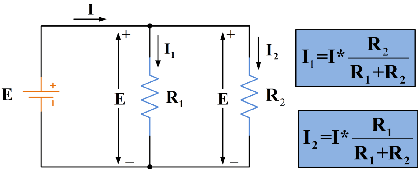
Figure 1: Current Ratios in Circuits
Analyzing Current Ratios in Electrical Circuits
In parallel circuits, the current splits among various branches based on each branch's resistance. This concept resembles voltage dividers but applies to currents instead. The current flowing through any resistor in the circuit, such as R1 compared to R3, keeps a fixed ratio, even if the source voltage changes. For example, if the current through R1 is always twice that of R3, this ratio remains steady regardless of fluctuations in the source voltage. This predictable behavior is explained by Ohm's Law, which states that the current through a resistor in a parallel circuit is inversely proportional to its resistance.
Parallel circuits serve as current dividers, splitting the total current from the source into parts that are inversely related to the resistances. This can be expressed mathematically as
where  is the current through the resistor
  and
and  is the constant voltage across all parallel components. This relationship shows that current division in a parallel circuit depends not only on resistance values but also on the principle of current conservation, which dictates that the total current entering a junction equals the total current leaving it.
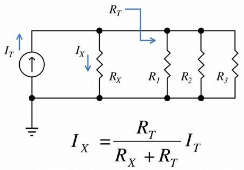
Figure 2: Current Divider Formula
Mastering the Current Divider Formula
The current divider formula is a fundamental concept in electrical engineering for analyzing current flows in parallel resistive circuits. It shows that the current through any branch in a parallel circuit is inversely proportional to the resistance of that branch, compared to the total resistance of all branches. This helps simplify the process of determining how current is distributed among different pathways in a circuit.
To express this quantitatively, the current through a resistor in a parallel circuit is calculated using:
Here,  is the total current entering the parallel network,
  is the equivalent resistance of the parallel network, and
  represents the resistance of each branch., calculated by:
This formula is needed for engineers and technicians because it allows them to predict the current in any branch of a parallel circuit without measuring the voltage across each component. Beyond simplifying calculations, it helps design circuits with desired current characteristics. This optimization is dynamic for enhancing the performance of systems like power supplies and ensuring safety by making sure components operate within their current limits.
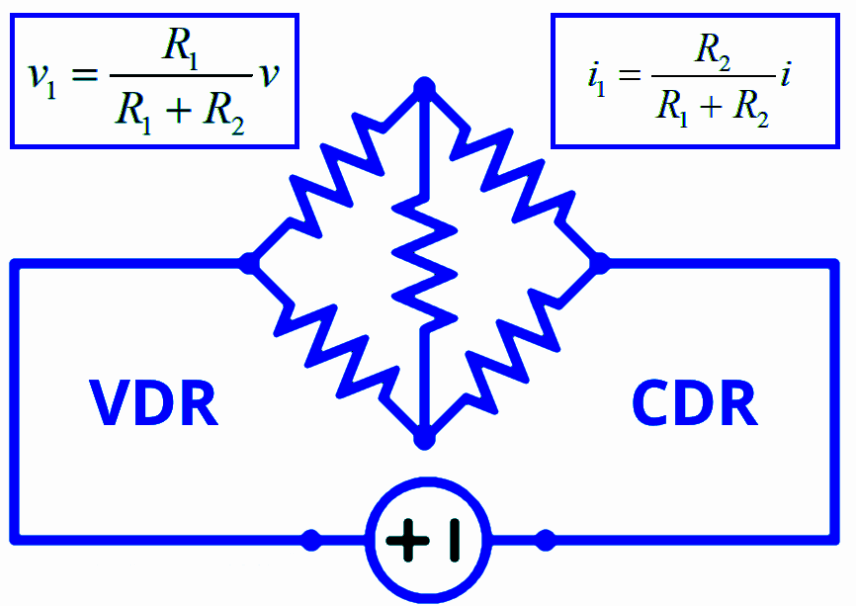
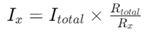
Figure 3: Current Divider and Voltage Divider Formulas
Comparing Current Divider Formula vs. Voltage Divider Formula
Understanding the differences and similarities between the voltage and current divider equations can help prevent mistakes such as incorrectly applying resistor ratios. Both formulas distribute a total input (current or voltage) across components based on their resistances, but they operate under different conditions and use distinct approaches to resistance.
The current divider formula is used in parallel circuits to find the current through a particular branch. It shows that the current in a branch is inversely proportional to its resistance compared to the total parallel resistance. This means branches with lower resistance will carry a higher proportion of the total current. The voltage divider formula applies to series circuits and calculates the voltage across a specific component. It indicates that the voltage across a component is proportional to its resistance compared to the total series resistance. Therefore, components with higher resistance will have a larger share of the total voltage drop.
Both formulas create ratios of key, less than one, highlighting their function as dividers. They split an input (current or voltage) into smaller, proportional parts rather than increasing the values. Identifying whether a circuit is in series or parallel is required for using the correct formula. This distinction determines how the input is divided—current among parallel paths or voltage along a series path.
Exploring the Use of Current Dividers in Electrical Metering
Current dividers are needed in electric meter circuits, enabling precise control of current flow to measure electrical usage accurately. These circuits often require directing a specific fraction of the current through a sensitive instrument, which is achieved using a shunt resistor calculated with the current divider formula.
Consider an electric meter designed to measure large currents that standard instruments can't handle directly. By placing a shunt resistor in parallel with the measuring device, the current divider formula ensures that only a safe, predetermined fraction of the current flows through the meter.
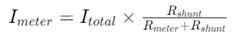
The calculation involves selecting a shunt resistor value that, combined with the meter's resistance, appropriately divides the current. Here,  is the total current,
 is the resistance of the meter, and
  is the resistance of the shunt resistor. By carefully choosing
  , engineers can control the current flowing through the meter, ensuring it remains within safe operational limits while providing accurate data for total power usage calculations.
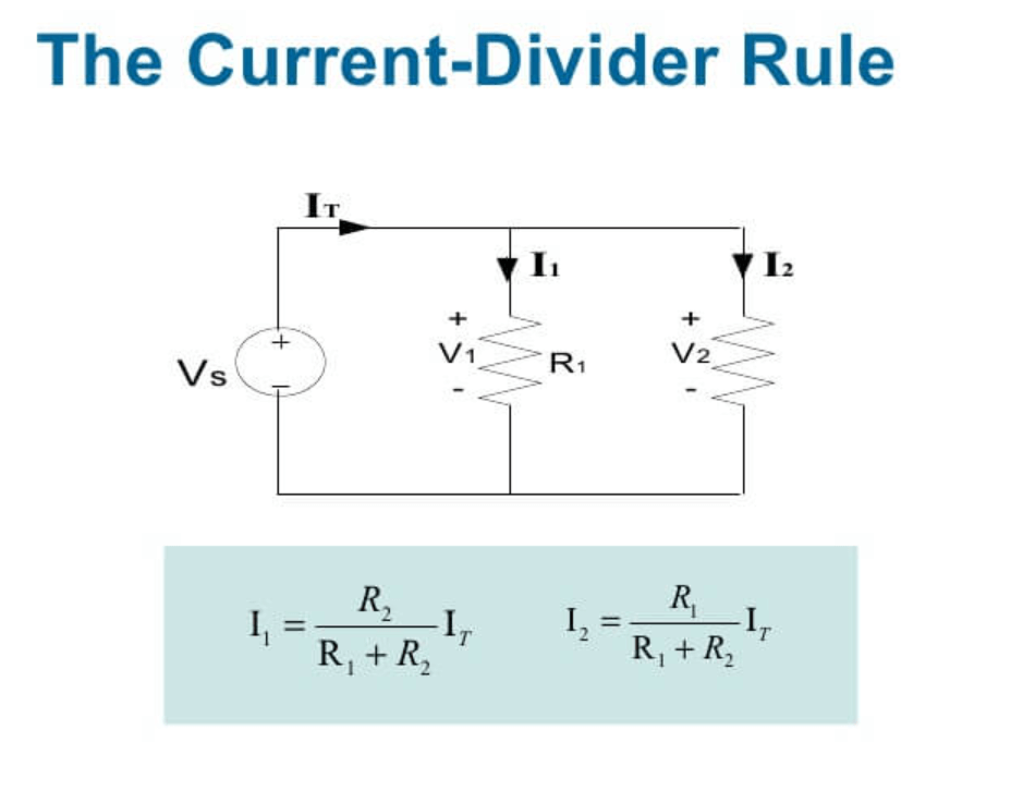
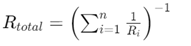
Figure 4: Current Dividers Rule
Detailed Procedures for Using the Current Divider Rule in Calculations
Calculating current distribution in parallel circuits using the Current Divider Rule (CDR) requires a systematic approach to ensure accuracy and reliability.
Step 1: Verify Circuit Configuration
First, confirm that the circuit is arranged in parallel. The CDR applies only to parallel circuits where the voltage across all components is the same, but the currents can vary based on resistance values.
Step 2: Determine Total Current
Next, identify the total current entering the parallel circuit. This can be measured directly from experimental data or derived using Ohm's Law. If using Ohm's Law, calculate the total current by dividing the total voltage by the equivalent resistance of the circuit.
Step 3: Calculate Equivalent Resistance
Calculate the total resistance of the parallel branches. This is done by finding the reciprocal of the sum of the reciprocals of all individual resistances: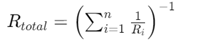
Step 4: Calculate Current for Each Branch
For each branch in the circuit, apply the CDR formula to determine the individual currents: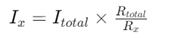 where
where is the resistance of the branch being analyzed.
Step 5: Repeat for Multiple Branches
If the circuit has multiple branches, repeat the calculation for each one. Ensure all resistances and currents are accounted for accurately.
Step 6: Verify and Validate
Finally, verify the calculations by checking that the sum of the currents in all branches equals the total current entering the circuit. This aligns with the principle of conservation of current. Additionally, confirm the assumed polarities and current directions to prevent errors in measurement or interpretation.
Classifying Prospects to Apply the Current Divider Rule in Circuit Design
The Current Divider Rule (CDR) is needed for accurate current distribution in various electrical engineering applications, playing a significant role in effective circuit design and management. It is particularly valuable in handling uneven loading in parallel circuits, where it provides precise predictions of current flow in each branch. This ensures that components are correctly rated and can handle their specific currents without the risk of overloading, which is serious in circuits with branches experiencing different current loads. Additionally, the CDR is instrumental in controlling power dissipation in circuits where overheating could cause damage, aiding in the stability and efficiency of high-power applications like power supply units and motor control systems.
CDR also has advantages in complex circuits with multiple branches. It enables engineers to understand how current is distributed on various paths, which is beneficial for optimizing circuit layout and selecting appropriate components. This deep insight helps ensure that each part of the circuit operates within safe limits, a necessity during the design phase, maintenance, and troubleshooting. Overall, the CDR's ability to forecast and manage currents contributes significantly to the reliability and safety of electrical systems.
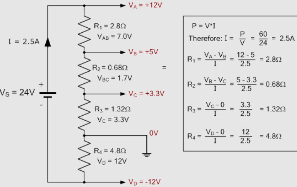
Figure 5: Resistive Current Divider
Design and Function of Resistive Current Divider Circuits
Resistive current divider circuits are fundamental in electrical engineering, illustrating how currents distribute in parallel setups. These circuits typically involve two or more resistors in parallel, each receiving a portion of the total input current, which then recombines at the return point to the source.
Functionality Based on Kirchhoff’s and Ohm’s Laws
The operation of resistive current dividers relies on Kirchhoff's Current Law, which states that the total current entering a junction equals the total current leaving it. This ensures that the sum of currents through each parallel path equals the initial current entering the circuit.
Ohm's Law is also significant in these circuits, providing the method to calculate the current through each resistor. Since the voltage across all resistors in a parallel circuit is constant, Ohm's Law allows for easy computation of the current in each branch:  where V is the voltage across the resistors, and Rx is the resistance of a specific branch.
Resistive current divider circuits are straightforward examples of current division. In practical terms, analyzing how to control these currents is needed for designing circuits that require precise current levels through various components. For example, in systems where different components need specific current levels to function optimally, a resistive current divider can allocate the correct currents based on resistance values.
Understanding Current Division through Conductance
An efficient way to analyze current divider circuits is by using conductance instead of resistance. Conductance, the reciprocal of resistance , simplifies the process of understanding current distribution in parallel resistor circuits.
Conductance in Parallel Circuits
In parallel circuits, calculating the total conductance is straightforward. The total conductance Gtotal is the sum of the conductances of each parallel resistor: 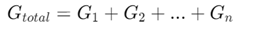 where
where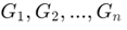 are the conductances of the parallel resistors.
Calculating Currents Using Conductance
Once you know the total conductance, finding the current through each branch becomes easier. The current Ix in a branch with conductance Gx is given by:

This formula allows direct computation of branch currents using conductance, bypassing the need to first calculate equivalent resistance and then apply the traditional current divider rule.
Using conductance is particularly beneficial in complex circuits where calculating individual and total resistances can be tedious. Converting resistances to conductance simplifies the sums, making current calculations more direct and reducing potential errors. Adopting conductance for the current division enhances the flexibility and efficiency of circuit analysis.
How to Apply the Current Divider Rule Using Conductance
Using conductance to apply the Current Divider Rule provides a clearer way to analyze current flow in parallel circuits. This method aligns with the properties of electrical conductivity, offering an intuitive grasp of how currents distribute across different branches.
Compared to traditional resistance-based methods, using conductance simplifies current distribution calculations. In this approach, the conductance of each branch is in the numerator, highlighting that higher conductance (lower resistance) leads to higher current flow. The current through any branch in a parallel circuit is given by:
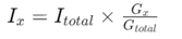
Here,Gx is the conductance of the branch,Gtotal is the sum of the conductance of all branches, and Itotal is the total current entering the circuit. This conductance-based method provides a clearer picture of current flow in circuits with multiple parallel paths. It is especially useful in complex systems, where conductance values directly measure how easily current flows through each component.
Key Instances for Utilizing the Current Divider Rule
A current divider rule is a key tool for analyzing current flow in complex electrical circuits, particularly in parallel branches with multiple resistors. This rule is needed for determining the individual currents through each resistor, especially in complex networks where direct measurement is challenging or impractical.
Parallel Resistor: This rule is specifically designed for parallel resistor arrangements. For example, in a circuit where resistors R1 and R2 are in parallel, the total current entering the node shared by R1 and R2 splits between them inversely proportional to their resistances. This division simplifies calculating the currents in each branch, making circuit analysis more efficient and reliable for various applications, from basic electronics to advanced engineering systems.
Uniform Voltage Requirement: A key condition for applying the current divider rule is having the same voltage across each parallel branch. This uniform voltage ensures accurate calculations, assuming identical voltage levels for each resistor. If there are voltage discrepancies, circuit modifications like source transformations—converting voltage sources to equivalent current sources and vice versa—may be required to restore conditions suitable for the current divider rule.
Limitation to Linear Components: The current divider rule works only with linear components that follow Ohm's law, meaning the current through a component is proportional to the voltage across it and inversely proportional to its resistance. This rule doesn't apply to non-linear elements like diodes or transistors, whose resistance varies with the applied voltage. For circuits with such elements, analysts need alternative methods tailored to non-linear characteristics, such as piecewise linear analysis or specialized simulation software.
Steady-State Condition: The current divider rule assumes the circuit is in a steady state, where all voltages and currents remain constant over time. This condition is significant because transient phenomena—like the switching on or off of components—can cause temporary fluctuations in current or voltage, potentially skewing the analysis. In dynamic conditions, more advanced methods, such as differential equation modeling or Laplace transformations, are better suited to capture and analyze transient behaviors, providing a detailed understanding of the circuit’s temporal dynamics.
Exploring the Current Divider Rule Across Various Scenarios
The Current Divider Rule is widely used in various real-world scenarios, ranging from simple circuits with two resistors to complex systems with multiple resistors and power sources. These examples demonstrate how the rule ensures effective and efficient circuit operation.
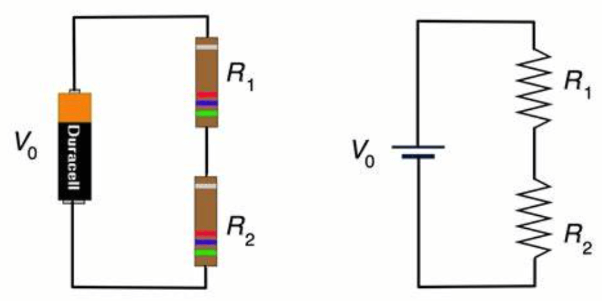
Figure 6: Basic Two-Resistor Circuit
Consider a simple parallel circuit with a total current of 10 amperes flowing into a node and splitting between two resistors,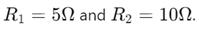
The Current Divider Rule calculates the current through each resistor as follows:
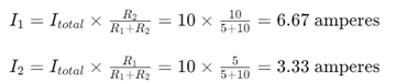
This example shows how current is divided proportionally based on resistance values, with the lower resistance drawing more current.
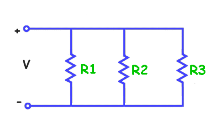
Figure 7: Complex Multi-Resistor Circuit
For a more complex scenario, consider a circuit with multiple resistors and a total current of 15 amperes. The resistors 
are connected in parallel. Using the Current Divider Rule:
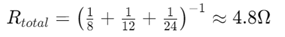
The current through each resistor can be found by:
This calculation demonstrates how different resistances affect the current distribution.
The Impact of Current Dividers in Modern Electronic Systems
Current dividers play a dominant role in various applications within electronics and electrical engineering. They are required for functionalities ranging from component biasing to system monitoring.
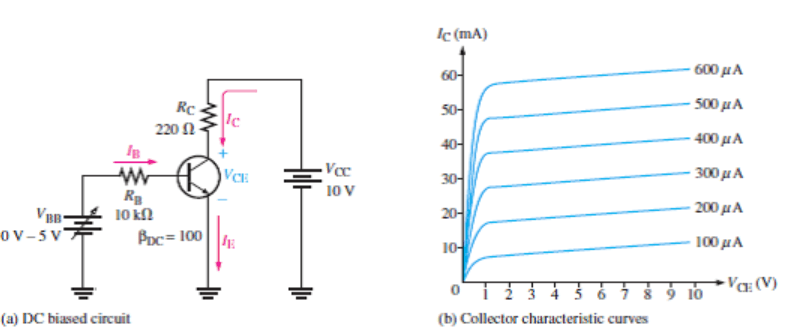
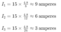
Figure 8: Biasing Transistors in Electronic Circuits
Current dividers are required for biasing transistors. By accurately dividing the current flowing to a transistor's base, they help set its operating point within the active region. This ensures stable amplifier performance and efficient switching in digital circuits.
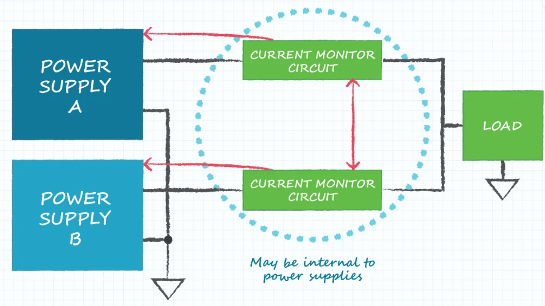
Figure 9: Current Distribution of Power Supplies
In power supply circuits, current dividers distribute current among various components safely and efficiently. This prevents component overload and maintains stable output voltages under varying load conditions, enhancing the reliability and efficiency of power supplies.
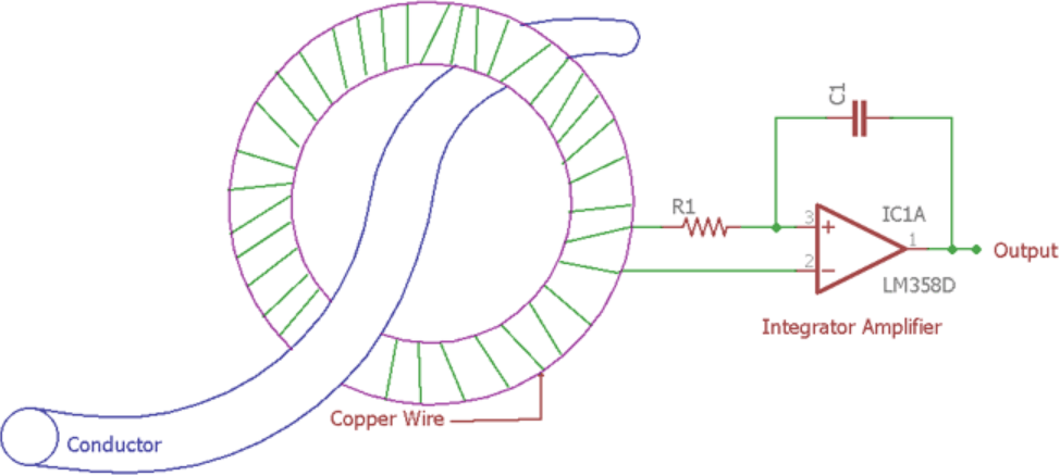
Figure 10: Current Sensing Mechanisms
Current dividers are conclusive in current sensing applications. They direct a manageable amount of current through sensors, which is chief in high-current environments like motor control systems. Measuring a small, proportional current accurately allows effective system monitoring and control.
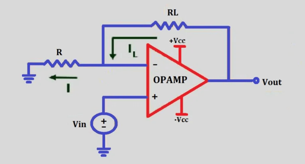
Figure 11: Voltage-to-Current Conversion
In voltage-to-current conversion processes, current dividers adjust output current based on a given input voltage. This is key in transducer interfacing, where sensor signals need to be converted into current for long-distance transmission without losing signal integrity.
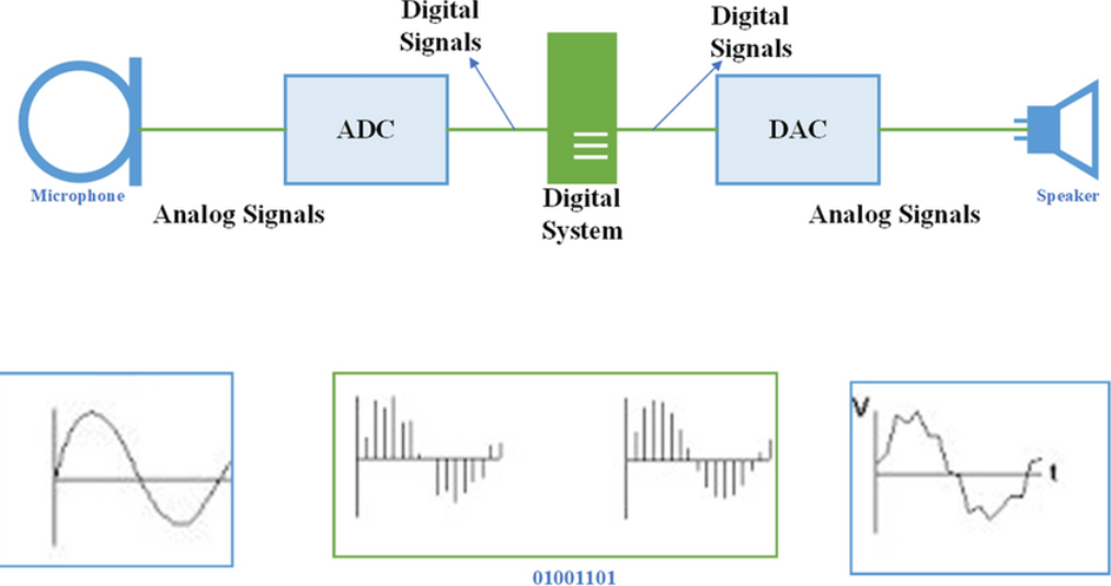
Figure 12: Distributing Signals in Electronic Systems
Current dividers also distribute signals within electronic systems, ensuring signals are shared between parallel pathways with minimal loss or distortion.
Conclusion
The exploration of current ratios and the Current Divider Rule in parallel circuits elucidates a fundamental aspect of electrical engineering with far-reaching applications. By understanding how current is distributed across different branches based on their resistance, engineers can design circuits that are both efficient and safe. The technical principles discussed, such as Ohm's Law and Kirchhoff's Current Law, are not just theoretical constructs but are key for practical applications, such as in the biasing of transistors, the design of power supply circuits, and the implementation in current sensing mechanisms.
Frequently Asked Questions [FAQ]
1. What is the formula for the current divider of a capacitor?
In a circuit containing capacitors, the current divider rule is based on the impedances (which depend on the frequency due to capacitors having frequency-dependent reactance). The formula for the current through a capacitor in a parallel network is:

Where I is the total current entering the network Zc is the impedance of the capacitor, and Ztotal is the equivalent impedance of the parallel network.
2. What is a voltage divider and current divider in a circuit?
A voltage divider is a circuit that outputs a fraction of its input voltage across a particular load. It typically consists of two resistors in series, with the output voltage taken across one of them.
A current divider is a configuration where the incoming current splits into multiple paths in a circuit with different branches having their impedance. The distribution of current depends on the impedance of each branch.
3. What is the mathematical expression of the current divider circuit?
For a basic current divider circuit with two branches having impedances Z1 and Z2 the current through Z1 is given by:
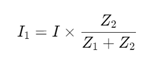
This formula applies to any passive component (resistors, capacitors, inductors), adjusting the impedance appropriately.
4. How to solve for current?
To solve for current in a circuit, you typically use Ohm’s Law,
where V is the voltage, I is the current, and R is the resistance. In more complex circuits, you might use Kirchhoff's Current Law (KCL) and Kirchhoff's Voltage Law (KVL) along with the impedance values for capacitors and inductors if present.
5. What is the rule for voltage and current in a circuit?
Ohm's Law is fundamental for understanding relationships in electrical circuits, stating that the current through a conductor between two points is directly proportional to the voltage across the two points and inversely proportional to the resistance.
Kirchhoff's Current Law (KCL) states that the total current entering a junction must equal the total current leaving the junction.
Kirchhoff's Voltage Law (KVL) states that the sum of the electrical potential differences around any closed network is zero.