on May 7th
837
Mastering the 555 Timer: Principles, Modes, Applications, and Practical Implementation
In this article, we explore the 555 timer, a seminal integrated circuit that revolutionized electronic devices upon its debut in 1971. This chip is known for its versatility and is used in everything from everyday household items to advanced spacecraft technology. We delve into the principles, structure, and applications of the 555 timer, particularly focusing on its utility in achieving precise control and timing in electronics projects.
Catalog
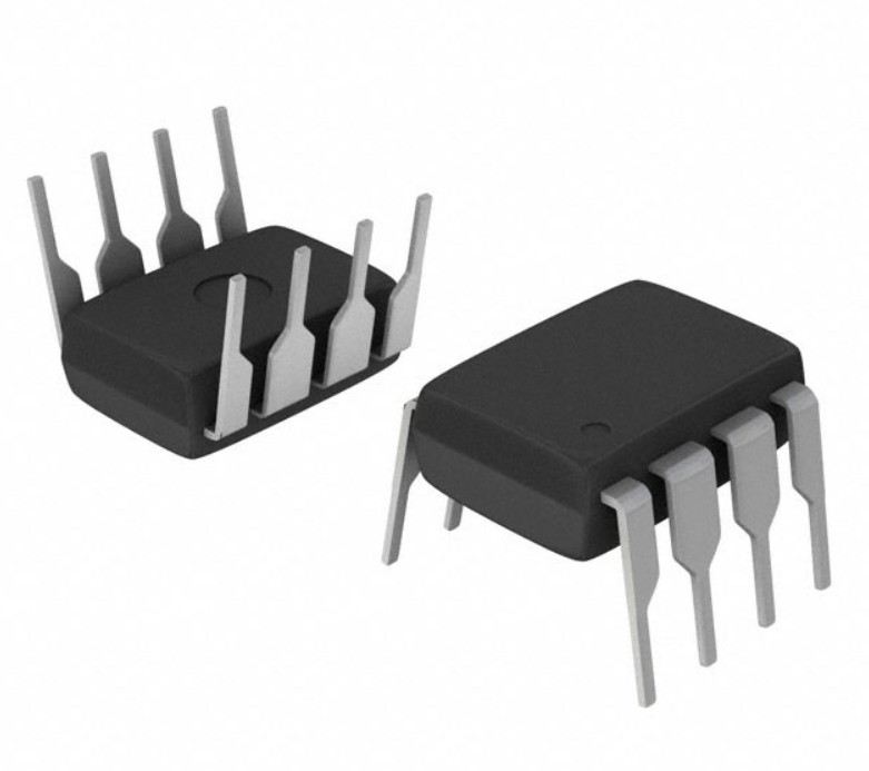
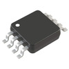
Figure 1: 555 Timer
Introduced by Hans Camenzind in 1971, the 555 timer is notable for its three 5kΩ resistors. These resistors form a voltage divider key to the timer's function, allowing it to control time intervals accurately. This chip plays a significant role in a wide range of electronic equipment due to its simple yet effective design, encompassing only 8 pins yet housing approximately 25 transistors, 2 diodes, and 16 resistors.
The 555 timer operates in three modes: monostable, bistable, and astable. Each mode serves different functions:
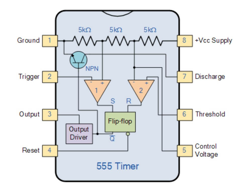
Figure 2: The 555 Timer Is Famous for Its Three 5kΩ Resistors
• Monostable mode provides a single, timed pulse, useful for creating precise delays.
• Bistable mode allows the timer to switch between two stable states, ideal for switches and toggles.
• Astable mode generates continuous oscillations, perfect for driving pulse width modulated (PWM) signals and creating sound effects.
The chip's flexibility makes it a favorite among hobbyists and professional engineers alike, celebrated for its reliability and precise timing capabilities.
When using the 555 timer, precision in selecting and setting resistors and capacitors helps define timing intervals. For instance, in a simple LED blinking circuit, adjusting these components changes the frequency and duration of the LED's flashes. This adjustment affects the waveform of the output signal and the overall stability and efficiency of the circuit.
For beginners, the initial learning curve might seem steep, especially understanding the impact of the internal 5kΩ resistors on the timer’s functionality. However, practical experimentation, such as varying resistance and capacitance to witness the resulting changes in output, can enhance understanding and intuition in circuit design.
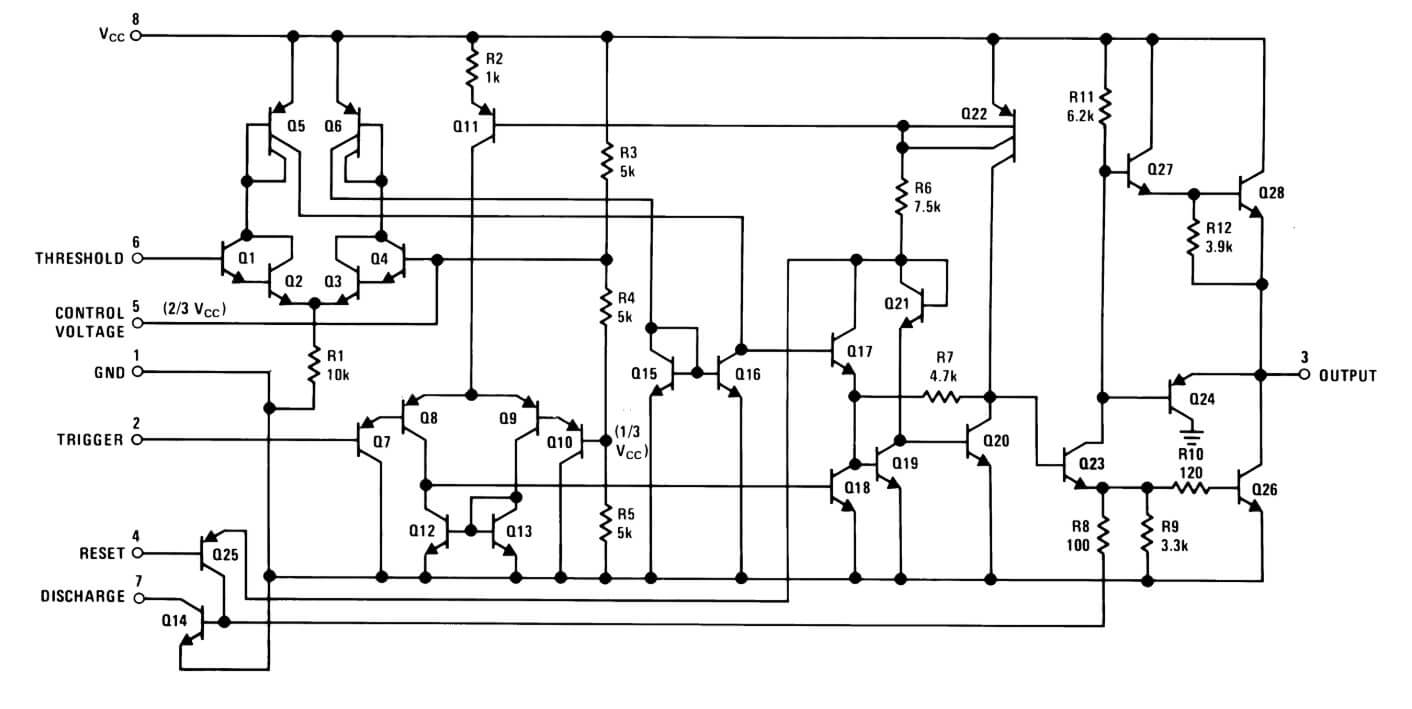
The 555 timer is a compact and efficient integrated circuit made up of 25 transistors, 2 diodes, and 15 resistors. These elements work together to form a robust timing control system. This circuit is built around several key components: two comparators, an RS flip-flop, a voltage divider, and an output stage.
Figure 3: 555 Timer Schematic Diagram
Voltage Divider
The voltage divider in the 555 timer is crafted from three 5kΩ resistors aligned in series. This setup splits the incoming supply voltage into two key reference voltages—1/3 and 2/3 of the initial voltage. These reference points are integral to the timer’s control mechanisms because they supply the necessary reference voltage for the comparators.
Comparators
The role of the comparators is to continuously check the external input signal, such as the voltage entering from an external circuit, and measure it against the internally set reference voltages (1/3Vcc and 2/3Vcc). Depending on whether the input voltage exceeds or falls below these reference points, the comparator responds. It sends out a high signal if the input is higher and a low signal if it's lower. This binary, on-off logic is fundamental for the precise functioning of the timer.
RS Flip-Flop
The signal from the comparators feeds into the RS flip-flop, a basic memory unit that toggles its output state based on the comparator’s signal. In a monostable mode operation, triggering the flip-flop sets off the timer for a predetermined duration.
Output Stage
The output stage of the 555 timer is designed to connect directly to and drive various loads like LED lights or small motors, handling up to 200mA. This capability makes the 555 timer incredibly versatile, suitable for both hobby projects and more demanding industrial applications.
Practical Application Tips
When using the 555 timer, selecting the right external resistors and capacitors is key. These components are decisive in setting the timing duration and ensuring the stability of the operation. For instance, attaching a larger capacitor to pin 2 (trigger pin) extends the timer's duration. While these adjustments may seem minor, they significantly influence the timer’s performance.
By understanding and manipulating these elements, users can achieve exact control over time intervals. Whether creating specific clock signals or designing complex automated control systems, this precision is a must. Each component and each connection matters, laying the foundation for reliable and effective timing operations.
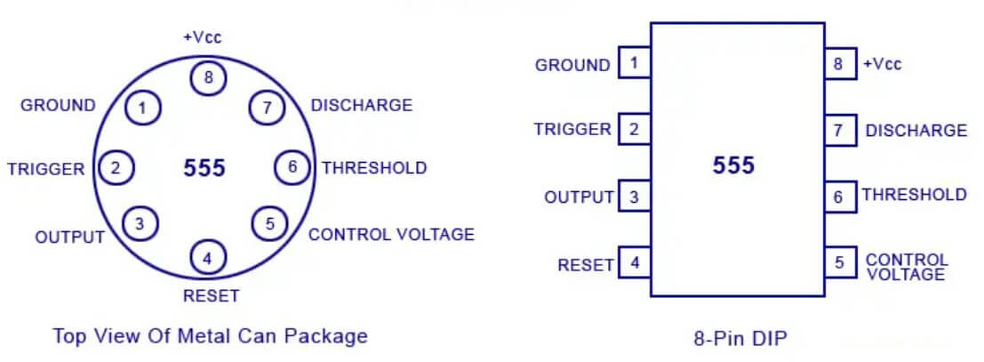
The 555 timer is an 8-pin integrated circuit widely used by engineers and electronics hobbyists to create various timing and oscillation applications. Each pin has a specific role, fundamental to implementing real-world electronic circuits effectively.
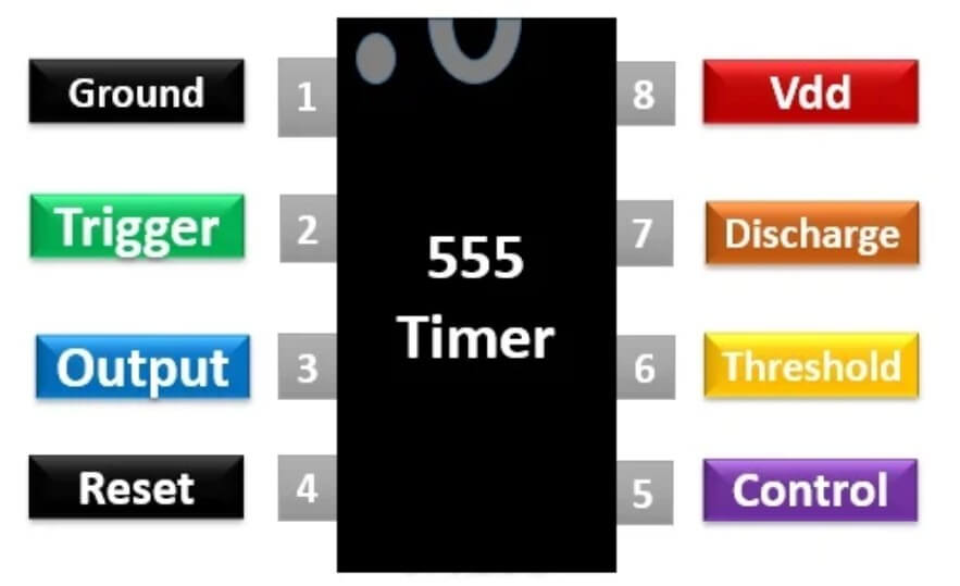
Figure 4: 555 Timer IC Pinout Diagram
Pin 1 (Ground)
Pin 1 connects directly to the negative terminal of your power supply. It's imperative to ensure a stable and solid connection on this pin, as poor grounding can lead to erratic circuit behavior or outright failures. Maintaining an uninterrupted connection here is a key step during setup.
Pin 2 (Trigger)
Pin 2 activates the timer's operations. This pin triggers a high-level output at pin 3 whenever its voltage drops below one-third of the supply voltage. In practical applications, designers often connect an external button or sensor, along with a resistor-capacitor network to this pin, to facilitate user-initiated start times.
Pin 3 (Output)
This pin directly reflects the timer’s state, providing a high output near the power supply voltage (reduced by a 1.5V dropout) and a low output near 0V. Capable of supporting 100mA to 200mA, pin 3 can power small devices directly, such as LEDs or small relays, without additional components.
Pin 4 (Reset)
Pin 4 serves to halt the timer’s current operation. Applying a low signal to this pin stops the timer and resets the output to low. This functionality is key in applications requiring an immediate cessation of timing, like safety shutoffs or during an error condition.
Pin 5 (Control Voltage)
Pin 5 allows for adjusting the internal threshold voltage by applying an external voltage, which alters the timer's period and frequency. This adjustment proves invaluable for fine-tuning the timer’s operation, especially in systems where variable timing is necessary.
Pin 6 (Threshold)
Pin 6 monitors the voltage level and switches the output to low when it hits two-thirds of the supply voltage. It's commonly used with pin 2 to establish and control the oscillation period in the timer's astable mode.
Pin 7 (Discharge)
In both the timer’s astable and monostable modes, pin 7 discharges the connected external capacitor. This discharge occurs as the output shifts between high and low, enhancing the precision of timing intervals.
Pin 8 (VCC Power Supply)
Pin 8 connects to the positive terminal of the power supply and typically accepts voltages between 5V and 15V. Ensuring the use of correct voltage is necessary to prevent malfunctions or damage from overvoltage.
Figure 5: 555 Timer IC Pinout Diagram
Gaining proficiency with these pins is key to effectively deploying the 555 timer in a project. This knowledge fosters the creation of everything from simple delayed switches to complex pulse generators, ensuring successful circuit design and implementation.
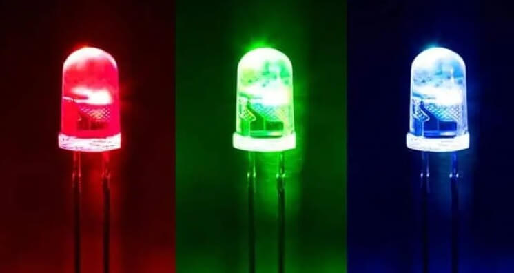
The 555 timer in astable mode functions as an oscillator, continuously switching its output from high to low. This oscillation is perfect for creating periodic functions like flashing an LED, producing sounds, or controlling motors.
When setting up the circuit, small adjustments to the resistor and capacitor values influence the flash frequency and stability of the LED. For instance, a higher capacitance extends both the on and off phases of the LED, resulting in a slower blinking pattern. Similarly, selecting the right resistor value helps protect the LED from excessive current, which could damage it, while also optimizing the circuit's power efficiency.
Experimenting with these circuits gives beginners a hands-on way to observe the interaction of electronic components. It also shows how timing in circuits is managed using basic elements, enhancing their grasp of the 555 timer's capabilities and encouraging further exploration in electronics.
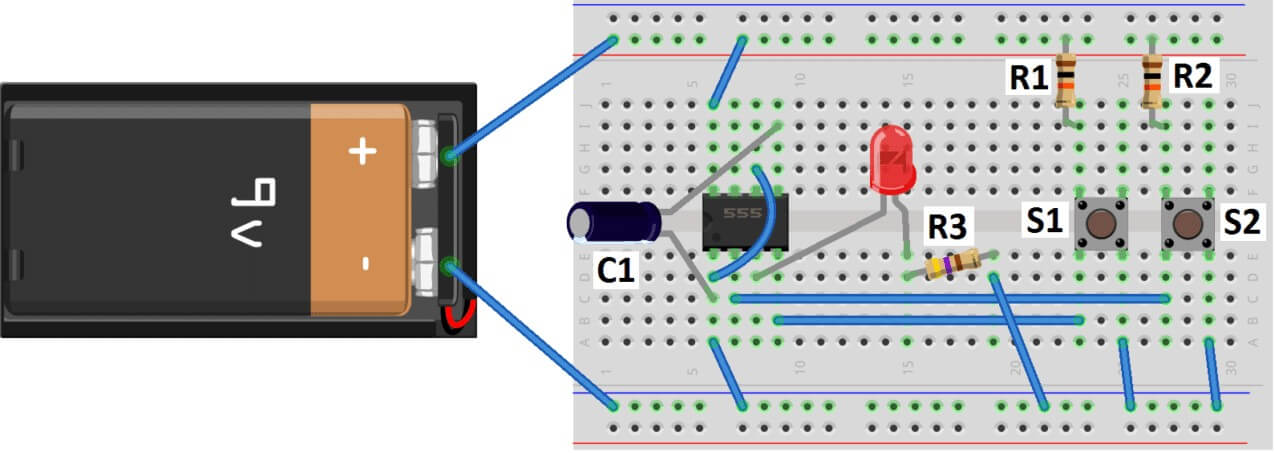
Figure 6: LED Circuit
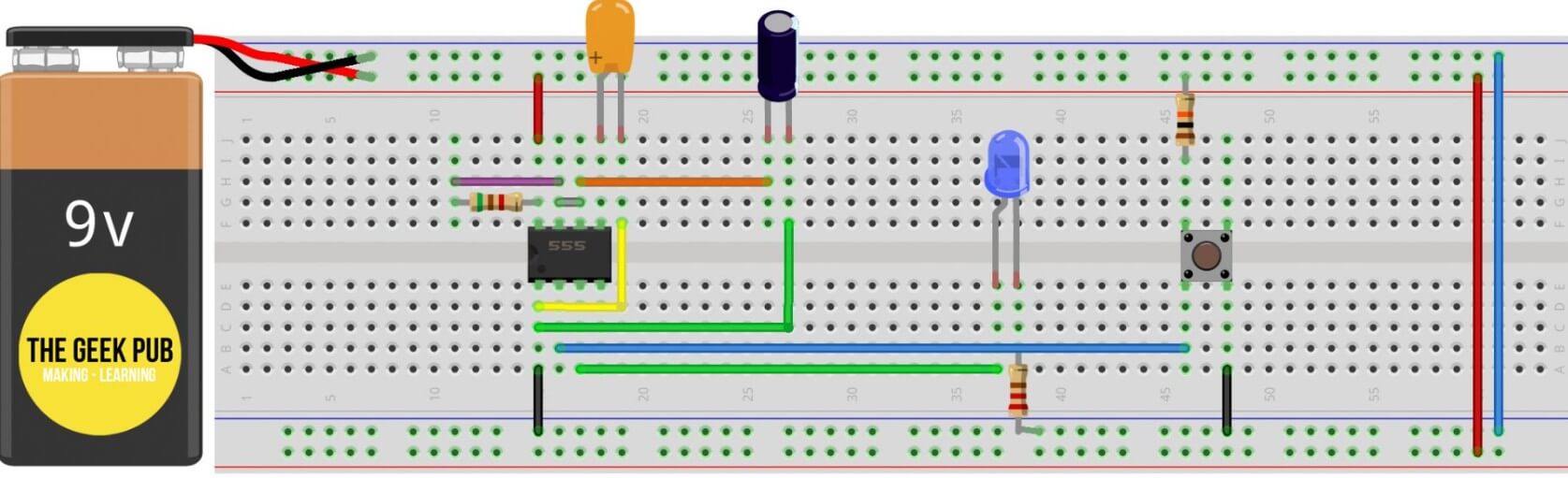
Building a Flashing LED Circuit
Assembling a flashing LED circuit with a 555 timer is an excellent introductory project for those new to electronics. The process is straightforward and provides a clear demonstration of the timer’s functionality in astable mode. Below, you’ll find the detailed steps and the components required.
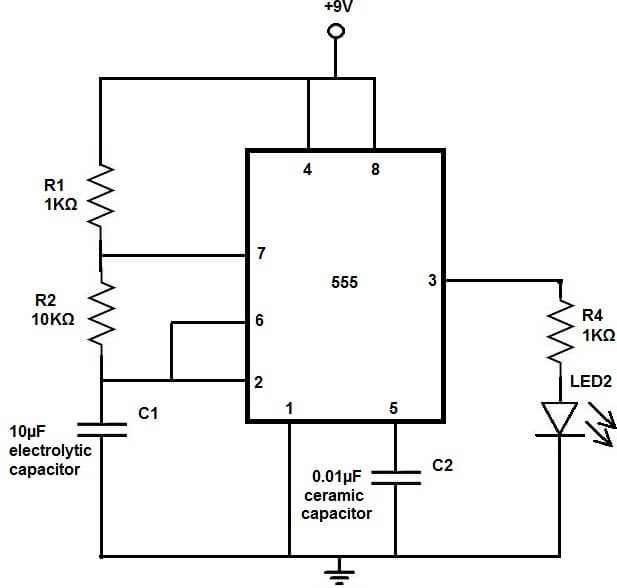
Figure 7: LED Flasher Circuit
Components Needed:
• 555 timer chip
• LED
• Resistor (to limit current to the LED)
• Capacitor (to set the flash frequency)
• Power supply (usually between 5V and 12V)
Assembly Instructions:
Connecting the Power Supply:
• Attach pin 8 of the 555 timer to the positive terminal of your power supply.
• Connect pin 1 to the ground.
Configuring the Timer:
• To set the 555 timer for astable mode, link pins 2 and 6 together.
Adjusting Output Frequency:
• Connect one resistor from pin 7 to pin 8. This resistor will influence how quickly the capacitor charges.
• Attach another resistor from pin 7 to pin 6 and place a capacitor in series from pin 6 to ground. The chosen values of this resistor and capacitor will determine how fast the LED blinks.
Connecting the LED:
• Link the positive terminal of the LED to pin 3, which is the output pin of the 555 timer.
• Connect the negative terminal of the LED to the ground through a resistor. This resistor should be carefully chosen to ensure it’s strong enough to prevent any damage to the LED from too much current.
Through these steps, you can build a circuit that not only demonstrates basic electronic principles but also serves as a practical introduction to the dynamic functions of the 555 timer.
Monostable mode, often referred to as single-shot mode, provides a stable, brief high output from the 555 timer. This functionality is particularly useful for generating single-use timing or delay signals. Common uses include initiating sequences in doorbells or temporary alarms where a quick signal triggers a longer action.
In the process of constructing and testing a monostable circuit, adjusting the resistor and capacitor values allows for accurate control over the output's duration. For instance, increasing the capacitor's size extends the period that the output remains high, which is useful for applications needing extended signal lengths such as longer alarms.
Attention to the quality of components, especially the trigger mechanism, is key. Low-quality components can lead to inconsistent triggering and diminish the system's performance. Additionally, the choice of pull-up resistor influences circuit stability. It must be large enough to keep pin 2 at a high state under normal conditions and small enough to facilitate a rapid shift to a low state when triggered.
These settings enable the 555 timer to function effectively in roles beyond basic doorbells or alarms, including precision tasks like controlling camera flashes. Such versatility showcases the 555 timer's utility in diverse electronic projects.
Building a Circuit in Monostable Mode
The setup for a monostable mode circuit requires careful attention to signal and timing configuration. Here’s a step-by-step guide to assembling a monostable circuit with a 555 timer.
Figure 8: 555 Timer in Monostable Mode Example
Components Required:
• 555 timer
• Resistors (minimum of two)
• Capacitor (determines delay duration)
• Trigger switch (such as a button)
• Output device (e.g., buzzer or LED)
• Power supply (typically 5V to 12V)
Assembly Instructions:
Establishing Power Connection:
• Connect pin 8 of the 555 timer to the positive terminal of your power supply.
• Attach pin 1 to the ground.
Configuring the Trigger Mechanism:
• Attach a pull-up resistor to pin 2 and connect it to the positive power supply to maintain pin 2 usually high, preventing accidental triggers.
• Connect pin 2 to the ground via a trigger switch, allowing the voltage at pin 2 to drop briefly when the switch is activated, thereby initiating the timer.
Setting the Output Duration:
• Place a resistor between pin 6 (threshold) and pin 7 (discharge).
• Attach a capacitor from pin 7 to ground. The specific values of the resistor and capacitor determine how long the output remains high, managing the transition back to low after activation.
Connecting an Output Device:
• Link pin 3 to an output device, such as a buzzer or LED, enabling it to emit sound or light upon activation.
By following these steps, you can create a monostable circuit that not only demonstrates basic electronic principles but also effectively utilizes the dynamic functionality of the 555 timer.
Bistable mode enables the 555 timer chip to toggle between two stable states, functioning similarly to an electronic two-way switch. This mode is ideal for scenarios requiring simple switches or logic controls without time-based functions. Commonly, it's applied in straightforward automation systems, robot logic controls, and various switch operations.
Understanding and Setting Up the Bistable Mode
The success of using bistable mode hinges on the precise setting of the trigger mechanism and maintaining stable outputs. The quality and setup of the control buttons significantly affect system performance, as inferior buttons can lead to jitter and frequent, unintended state changes.
To set the trigger, connect pins 2 and 6. Here's the operational logic: pressing a button changes the output from one state to another, which then holds until the button is pressed again. This setup is perfectly suited for designing simple logic circuits, such as those used to change a robot's direction or for basic data storage.
Beyond simple electronic switches, the bistable mode is also adaptable for more complex tasks like automated control systems that require elementary decision-making. Its simplicity and reliability make it a helpful tool in electronics projects.
Configuring Bistable Mode
In bistable mode, the 555 timer's output (either high or low) depends on an external trigger and remains unchanged until the next trigger event. While the setup is straightforward, a precise circuit design helps ensure both stability and responsiveness.
Figure 9: Example Bistable Mode Circuit
Required Materials:
• 555 timer chip
• Resistor
• Trigger switch (button or sensory device)
• Output devices (LEDs, electronic locks, motors, etc.)
• Power supply (typically 5 to 12V)
Construction Steps:
Power Connections:
• Connect pin 8 to the positive power supply and pin 1 to ground.
Set the Trigger Mechanism:
• Link pin 2 and pin 6 directly and through a pull-down resistor to the ground, ensuring the pin stays low without a trigger signal.
• Connect pins 2 and 6 to the positive supply through a push button for activation.
Output Configuration:
• Connect pin 3 (output pin) to an output device like an LED or another controller.
This direct and detailed approach to bistable mode configuration emphasizes practical handling and logical operation, making it accessible for those implementing or learning about simple control systems in electronics.
The 555 timer can supply up to 200mA, making it suitable for directly powering small motors or several LED lights. By adding external components like transistors or MOSFETs, the 555 timer's capacity increases, allowing it to handle larger loads in automated control systems.
When selecting a transistor or MOSFET, it's essential to ensure it can handle the expected voltage and current. For heavier loads, extra heat dissipation, such as heat sinks, may be necessary.
Pairing a 555 timer with a transistor or MOSFET gives users greater flexibility to manage high-power devices. This setup expands the 555 timer's use in automation systems.
Direct Drive Load
Basic Setup:
LED String: Connect several LEDs to output pin 3, including suitable current-limiting resistors to protect them from overcurrent. For instance, with a 12V power supply driving 10 LEDs, place a 120Ω resistor in series with each LED.
Small Motors: Connect a motor directly to pin 3 if it requires less than 200mA. This straightforward approach works well within the current limit.
Expanded Circuit for Larger Loads
Materials Needed:
• 555 Timer Chip
• Suitable Transistor (e.g., NPN) or MOSFET
• Flywheel Diode (for inductive loads)
• Control Resistor
• Power Supply
• Load (e.g., larger motors or high-power LEDs)
Steps for Assembly:
Transistor Driver Setup:
Place a small resistor between pin 3 and the transistor's base (NPN) or gate (MOSFET) to control the gate current.
Connect the collector (NPN) or drain (MOSFET) to one side of the load. Connect the other side of the load to the power supply's positive terminal.
Link the emitter (NPN) or source (MOSFET) to the negative power terminal.
For inductive loads like large motors, add a flywheel diode between the load and transistor to protect from voltage surges.
Testing and Adjustments:
Verify all connections are correct before powering up.
During testing, observe load response and check the transistor for overheating. If excessive heat is detected, consider installing heat sinks.
To manage loads surpassing 200mA, the 555 timer needs an external transistor to boost its driving power. NPN transistors or MOSFETs are commonly used for this purpose. They not only handle high-power motors or extensive LED strips effectively but also ensure circuit stability. Below are detailed instructions on implementing these measures, along with key operational considerations.
Required Materials
• 555 Timer Chip
• NPN Transistor or MOSFET
• Resistor (for base or gate)
• Flywheel Diode (for inductive loads)
• High-Power Load (e.g., motor or LED strip)
• Power Supply (matching load and transistor voltage/current needs)
Implementation Steps
Connect the 555 Timer:
Configure the 555 timer based on the intended application mode, like monostable or astable.
Select and Set Up the Transistor:
For an NPN Transistor. Link the output pin (pin 3) of the 555 timer to the transistor’s base using a resistor between 1kΩ and 10kΩ to limit the base current.
For a MOSFET. Connect the 555 timer's output to the MOSFET gate via a higher resistance, usually 10kΩ to 100kΩ, since MOSFETs are voltage-driven.
Connect the Load:
Attach the transistor’s collector (NPN) or drain (MOSFET) to one end of the load.
Connect the load’s other end to the positive power supply terminal.
If the load is inductive (like a motor), add a flywheel diode between the load and the transistor. The diode should face opposite the power supply to guard against voltage surges.
Test and Adjust:
Check connections carefully before powering up the circuit.
Observe the load’s response and monitor the transistor for overheating. If it gets too hot, use a heat sink to prevent damage.
Key Considerations During Operation:
Transistor Selection: Choose a transistor with the appropriate maximum current, voltage capacity, and on-threshold. MOSFETs generally work best for high-current use due to their low on-resistance.
Resistor Calculation: Carefully calculate the base or gate resistor to ensure the transistor properly responds to the 555 timer output.
Heat Dissipation: High-power loads generate significant heat, so apply appropriate cooling measures like heat sinks to maintain performance and avoid damage.
Following these steps, you can use the 555 timer to efficiently manage large loads beyond 200mA. This configuration broadens the 555 timer’s capabilities, allowing it to be effective in various automation and control scenarios.
This article provided a detailed analysis of the 555 timer's operation and why it's so widely used. The 555 timer's multifunctionality and reliability make it invaluable for electronics enthusiasts and engineers alike, showing its unmatched value in complex electronic systems. Practical circuit designs ranging from simple experiments to intricate automation applications demonstrate its flexibility and high-current output capabilities. Readers should now be well-versed in the 555 timer's functionality and can confidently apply this knowledge to real-world projects. By harnessing creativity, they can tackle practical challenges and contribute to the ongoing innovation in electronic technology.
Frequently Asked Questions [FAQ]
1. How Does a 555 Timer Work in a Circuit?
The 555 timer is a versatile integrated circuit with three main modes: astable, monostable, and bistable. Here's a simplified explanation:
Key Components:
The chip includes two voltage comparators, an SR flip-flop, an output stage, and a discharge transistor.
Inputs and Internal Signals:
Trigger and Threshold Inputs:
Two main input pins receive voltage signals.
Control Voltage Input:
Modifies the internal reference voltage.
Internal Operation:
The comparators monitor the Trigger and Threshold pins' voltage levels against an internal reference.
When Trigger voltage is below one-third of the supply voltage, the lower comparator sets the SR flip-flop to output a high signal.
If Threshold voltage exceeds two-thirds of the supply voltage, the upper comparator resets the flip-flop, resulting in a low output.
Discharge Transistor:
Connected to pin 7, the discharge transistor is controlled by the flip-flop.
In astable mode, it intermittently discharges a timing capacitor, creating a repetitive oscillation.
In monostable mode, it discharges the capacitor when the output goes low.
2. Example of a 555 Timer Application
A popular use for the 555 timer in astable mode is to create an LED flasher circuit:
Circuit Setup:
A resistor, a timing capacitor, and an LED are needed.
Operation:
The capacitor charges through a resistor.
Once the voltage reaches two-thirds of the supply voltage, the discharge pin is triggered, discharging the capacitor and resetting the cycle.
This cycle makes the LED blink at a frequency determined by the resistor and capacitor values.
3. How to Make a Simple 555 Timer Circuit
Here's a step-by-step guide to assembling an astable 555 timer circuit:
Gather Components:
• 555 timer IC
• Two resistors (R1 and R2)
• One electrolytic capacitor (C1)
• Power supply (5-15V)
• LED
• Connecting wires
Circuit Assembly:
Connect pin 8 (VCC) to the positive power supply.
Connect pin 1 (GND) to ground.
Place resistor R1 between pins 8 and 7.
Connect resistor R2 between pins 7 and 6.
Attach capacitor C1 between pin 6 and ground.
Tie pin 4 (Reset) to VCC.
Optionally, ground pin 5 (Control Voltage) through a 0.01 µF capacitor.
Connect pin 3 (Output) to the LED's positive leg via a current-limiting resistor, then ground the other leg.
Adjust Timing:
Calculate the oscillation frequency using:
frequency = 1.44 / ((R1 + 2 * R2) * C1)
Test the Circuit:
Power up the circuit. The LED should start blinking.
Change resistor and capacitor values to modify the blinking rate.
4. Understanding Voltage Control in a 555 Timer Circuit
The voltage in a 555 timer circuit is primarily set by its application mode, such as astable or monostable. Typically, the voltage range is from 4.5 volts to 15 volts, depending on the supply voltage (Vcc). The output fluctuates between nearly 0 volts (ground) and close to Vcc. During operation, the circuit manages timing intervals by varying the voltage over a timing capacitor. For more advanced control, an external voltage can be applied to fine-tune the oscillation frequency, a method often referred to as voltage-controlled oscillation (VCO).
5. The Most Common Use of the 555 Timer Today
Today, the 555 timer is predominantly employed as an oscillator or a pulse generator, especially for generating clock pulses in digital circuits. It is key in creating precise square wave signals needed for timing and control applications. Additionally, it's widely used in pulse-width modulation (PWM) circuits. This application is crucial for adjusting the brightness of LEDs or controlling motor speeds, allowing for a wide range of speed settings and light intensities.
6. Advantages of Using a 555 Timer
Versatility: The 555 timer is capable of operating in multiple configurations, such as generating continuous oscillations in astable mode or producing a single pulse in monostable mode.
Ease of Use: It requires only a handful of external components to function, simplifying the design and assembly process for many projects.
Affordability: Due to its low cost, the 555 timer is accessible for both hobbyists and professional projects, making it a staple in electronic devices.
Stable Performance: The timer maintains a stable output, which is not easily affected by changes in temperature, ensuring reliable operation across different environments.
High Output Current: It can directly drive devices with currents up to 200mA, allowing it to power LEDs, small motors, and other components without additional hardware.
Precision: The timing intervals are highly accurate and can be easily adjusted with external resistors and capacitors, providing flexibility in the timing range and precision.
7. How Does a 555 Monostable Circuit Work?
A 555 timer in monostable mode produces a single pulse of a specific length. Here's a detailed explanation:
Triggering the Circuit:
Initially, the circuit sits in a stable state where the output (pin 3) is low.
When a short, low-voltage signal (below one-third of the supply voltage) reaches the trigger pin (pin 2), the timer starts, causing the output to switch to high.
Timing the Pulse:
The duration of the high output pulse depends on an external resistor (R) between Vcc and the discharge pin (pin 7), as well as a capacitor (C) between the threshold pin (pin 6) and ground.
Once the output is high, the capacitor starts charging through the resistor.
Ending the Pulse:
As the capacitor charges and its voltage reaches two-thirds of the supply voltage, the internal threshold comparator flips the output back to low, discharging the capacitor and resetting the circuit.
Key Components:
Resistor (R): Controls the rate at which the capacitor charges.
Capacitor (C): Stores charge and determines the pulse duration.
Pulse Duration Formula:
T = 1.1 × R × C
8. What is an Alternative to a 555 Timer Circuit?
Various alternatives to the 555 timer include:
Microcontrollers:
Flexible and programmable for multiple timing functions.
Specialized Timer ICs:
CD4538: Offers two precision monostable multivibrators.
NE566: A voltage-controlled oscillator.
Discrete Components:
Transistor-Based Oscillators: Uses discrete transistors and passive components for timing.
RC Oscillators: Simple circuits with resistors and capacitors, typically paired with amplifiers.
9. How Do You Set the Frequency on a 555 Timer?
To adjust the frequency of a 555 timer in astable mode (continuous oscillation), you'll need to change the values of two resistors and a capacitor.
Circuit Connection:
Resistor R1: Connect between Vcc and the discharge pin (pin 7).
Resistor R2: Connect between pin 7 and the threshold pin (pin 6).
Capacitor C: Connect between pin 6 and ground.
Take the output from pin 3.
Calculate Frequency:
Frequency (Hz) = 1.44 / ((R1 + 2 × R2) × C)
Calculate Duty Cycle:
Duty Cycle (D) = R2 / (R1 + 2 × R2)
Adjusting Resistors:
To Increase Frequency: Reduce the resistance of R1 and R2.
To Lower Frequency: Increase the values of R1 and R2.
Example Calculation:
If R1 is 10kΩ, R2 is 20kΩ, and C is 0.01µF, then the frequency is:
f = 1.44 / ((10k + 2 × 20k) × 0.01µF) ≈ 2.4kHz
Change the values of R1 or R2 to reach the desired frequency.
Share: