Mastering Schematic Symbols: A Guide to Electronic Circuit Design
In the intricate world of electronic design and maintenance, the ability to interpret and utilize schematic diagrams stands as a cornerstone of engineering proficiency. These diagrams, or schematics, transcend mere graphical representations, they embody the comprehensive blueprint of electrical connections, components, creation, and troubleshooting of electronic devices. The standardized symbols used within these schematics—ranging from basic components like resistors and capacitors to complex integrated circuits—play a pivotal role in bridging the gap between theoretical designs and practical applications. This guide delves into the nuances of schematic symbols and their operational significance, offering a detailed exploration of their types, meanings, and uses in various electronic circuits.Catalog
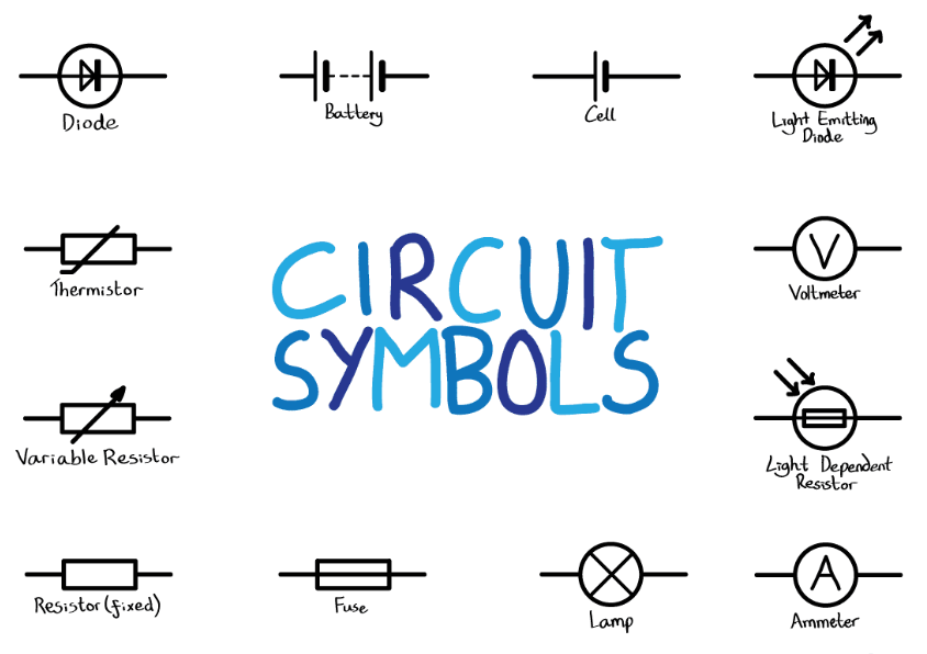
Figure 1: Circuit Symbols/ Schematic Symbols
Schematic Overview
A circuit diagram, or schematic, isn't just a graphic representation of electrical connections, components, and operations, it serves as the foundation for the entire process of electronic design and troubleshooting. Engineers and technicians use a set of standardized graphic symbols, known as schematic symbols, to clearly indicate the various components in a circuit and their connections.
These symbols range from simple resistors and capacitors to more complex integrated circuits. Each symbol is meticulously crafted to provide intuitive information about the type of component and its function. Within a circuit diagram, these symbols not only pinpoint the location of components but also reveal how they are electrically connected. Additionally, common pins or connecting lines in the schematic can be labeled with letters or abbreviations, enhancing the diagram's informativeness and practicality.
Globally, while there are various symbol variants, the standardized symbols provided by the International Electrotechnical Commission (IEC) and the Institute of Electrical and Electronics Engineers (IEEE) ensure a degree of universality and interoperability. This standardization is particularly vital for international projects and academic exchanges.
Schematic Symbols
Power Supply Symbols
Power supplies are essential in any electronic device, symbolized by a series of alternating long and short lines. These lines not only indicate the presence of a power source but also the type of electrical energy provided. In complex circuits, different symbols for power supplies, such as those for positive and negative systems, are used to clearly depict their configurations through the orientation and design of the symbols.

Figure 2: Universal Power Symbol

Figure 3: DC Power Supply Symbol on the Left, AC Power Supply Symbol on the Right
Resistor Symbols
Resistors, fundamental in controlling the flow of electricity, are represented differently in American and European standards. The American symbol is zigzag, while the European is a simple rectangle. Both styles effectively communicate the resistor's role and function.
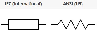
Figure 4: Resistor Symbols
Photoresistor (LDR) Symbols
The symbol for a light-dependent resistor (LDR) includes a circle with an arrow inside, indicating the effect of light intensity on its resistance.
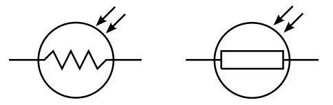
Figure 5: Photoresistor (LDR) Symbols
Fuse Symbols
Fuses are depicted simply as a line with a break, playing a key role in circuit protection, especially in high-voltage settings.
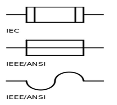
Figure 6: Fuse Symbols
Inductor Symbols
Inductors are shown as one or several loops, essential for generating the necessary magnetic field in circuits, crucial for handling AC signals.
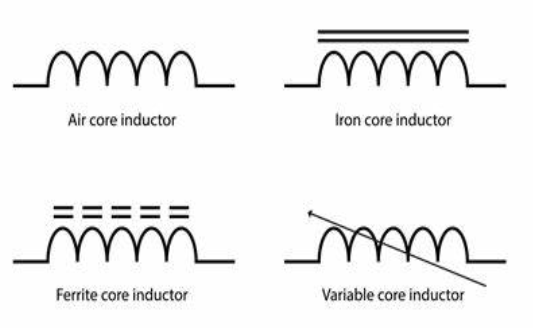
Figure 7: Inductor Symbols
Switch Symbols
Switches, used to control whether electricity flows through a circuit, are represented in various forms, from simple toggle switches to complex multi-position switches.
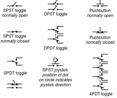
Figure 8: Switch Symbols
Capacitor Symbols
Capacitors, which store electrical charge and smooth out voltage fluctuations or separate DC from AC signals in circuits, are marked to distinguish polarized from non-polarized types. Polarized capacitors have a "+" sign to indicate installation direction.
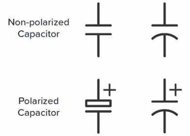
Figure 9: Capacitor Symbols
Potentiometer Symbols
Potentiometers control current through an adjustable resistance, symbolized similarly to a resistor but with an adjustment arrow, highlighting its variability.
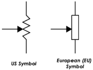
Figure 10: Potentiometer Symbols
Battery Symbols
Battery symbols, made up of series of lines of varying lengths, represent the energy and polarity of the battery, an indispensable energy source in portable electronic devices.
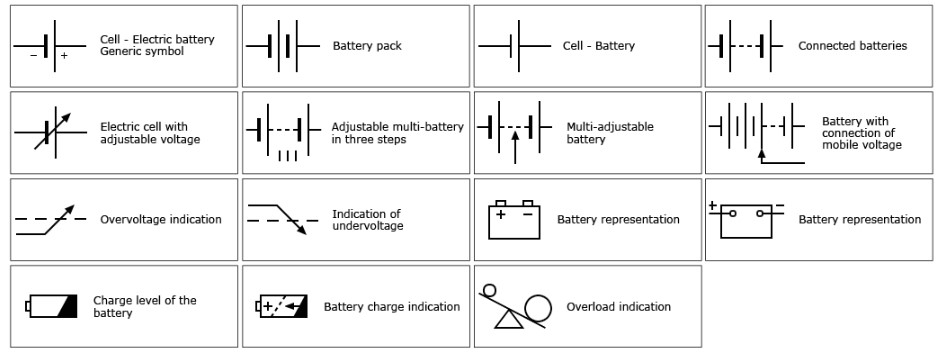
Figure 11: Different Battery Symbols
Diode Symbols
Diodes, which allow current to flow in only one direction, are varied from standard to special types like LEDs or Zener diodes, each with unique markings.
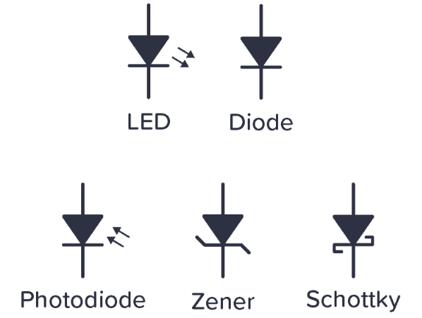
Figure 12: Diode Symbols
Transistor Symbols
Transistors, used to amplify and switch current, have symbols that reflect the characteristics and uses of different types.
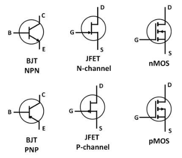
Figure 13: Transistor Symbols
Integrated Circuit (IC) Symbols
The symbol for an integrated circuit (IC) is a simple rectangle with pins, succinctly representing its complex functionality, with each pin's function depending on the IC's design.
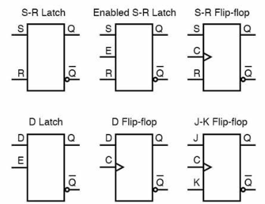
Figure 14: Integrated Circuit (IC) Symbols
Logic Gate Symbols
Logic gates, which perform basic logical operations on digital signals, have straightforward symbols that clearly convey their logical functions.
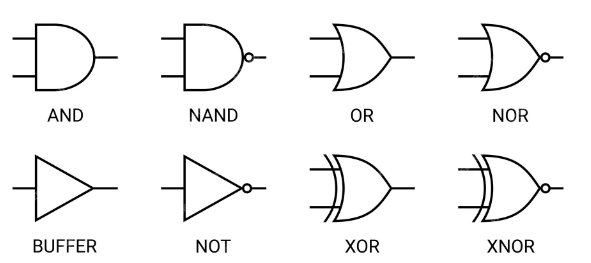
Figure 15: Logic Gate Symbols
Operational Amplifier (Op-Amp) Symbols
The operational amplifier symbol is a triangle, illustrating the dynamic inputs and outputs of the amplifier.
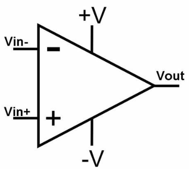
Figure 16: Operational Amplifier (Op-Amp) Symbols
Quartz Crystal Symbols
Quartz crystals, essential for generating stable clock frequencies, are depicted with two parallel lines and a small symbol for an oscillator, crucial for digital communication and precise control systems.
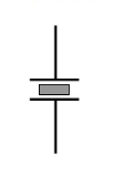
Figure 17: Quartz Crystal Symbols
How to Read Schematic Symbols and Values
In electronics, knowing how to read and interpret schematics is a necessary skill, especially during circuit design, testing, and maintenance. Schematics provide electronic engineers with a universal language that simplifies complex electronic systems into understandable symbols and connections. To accurately understand a schematic, it's essential to have a thorough knowledge of the symbols and values indicated on the diagram.
Symbols serve as identifiers for each component within a schematic. They are usually represented by a letter or a combination of letters followed by a number. The letter or combination denotes the type of component—'R' for resistors, 'C' for capacitors, 'L' for inductors, and 'Q' for transistors. The number distinguishes between identical components within the same circuit, such as R1, R2, R3 for the first, second, and third resistors respectively. This labeling not only maintains clarity in the schematic but also allows technicians to quickly and accurately locate specific components during circuit assembly or troubleshooting.
Next to each symbol, values are usually marked to describe the electrical characteristics of the component. For instance, a resistor labeled "R1 220Ω" indicates that it is the first resistor with a resistance of 220 ohms. Similarly, a capacitor marked "C1 10μF" identifies it as the first capacitor with a capacitance of 10 microfarads. These values determine the functionality and performance of the circuit. For example, the resistance value affects the current flow in the circuit, while the capacitance value impacts the response time in filtering or timing circuits.
Understanding and accurately reading these symbols and values is important for designing, building, and troubleshooting circuits. It requires technicians to not only recognize and understand every symbol and connection on the schematic but also to have a good grasp of the physical and electrical properties of electronic components. During circuit design or debugging, engineers rely on these markings to select appropriate components, ensuring that the circuit functions safely and effectively as intended.
The Role of Electronic Circuit Symbols
Electronic circuit symbols significantly streamline the creation and comprehension of circuit diagrams. These symbols are consistent across the industry, ensuring that anyone familiar with them can easily interpret different schematics. Each symbol incorporates elements such as dots, lines, letters, shading, and numbers, each adding specific details to clarify the component it represents.
To effectively read and utilize these diagrams, one must first learn the basic forms and meanings of the various symbols used. This foundational knowledge allows engineers and technicians to quickly grasp the functions and connections within the circuit. Circuit design heavily relies on these standardized symbols. They appear in electronic drawings that detail the wiring, layout, and placement of components within a device. By using these symbols, designers can clearly communicate where and how to arrange the parts during the assembly process. This clarity not only speeds up project timelines but also reduces errors in the construction of electronic devices, facilitating a smoother development process from schematic to assembly.
Conclusion
The mastery of reading and interpreting schematic diagrams is an indispensable skill that significantly enhances the efficiency and accuracy of developing and troubleshooting electronic circuits. Each symbol within a schematic is a gateway to understanding the electrical characteristics and functionalities of the components it represents, thereby enabling engineers and technicians to build, analyze, and refine electronic systems with precision. From power supply configurations to the intricacies of integrated circuits, the proper identification and application of these symbols ensure that electronic devices operate as intended, with optimal performance and reliability. As we have explored the variety of symbols and their specific contexts in electronic schematics, it becomes clear that these are not just mere markings but are critical tools that encapsulate the essence of electronic engineering. This foundational knowledge not only equips professionals to tackle complex designs but also empowers innovation and advancements in the field of electronics.
Frequently Asked Questions [FAQ]
1. How to understand a schematic diagram?
To understand a schematic diagram, start by identifying and familiarizing yourself with the symbols that represent the various components such as resistors, capacitors, diodes, and transistors. Note how these components are connected by lines, which represent electrical connections. Check for any labels or values next to the symbols which specify characteristics like resistance or voltage. Lastly, follow the flow of the circuit from the power source through different components to understand the circuit's functionality.
2. How to read electrical schematics for beginners?
Beginners can read electrical schematics by following these steps:
Identify Symbols: Learn the basic symbols like those for resistors, capacitors, and power sources.
Understand Connections: Recognize that lines between symbols represent electrical connections.
Check Labels: Look for any component values or identifiers, such as "R1 220Ω" for a resistor.
Trace Paths: Follow the circuit paths from inputs to outputs, noting how current flows through the components.
Refer to Legend: Use the schematic’s legend or key if available to clarify symbols or abbreviations.
3. What are the five basic electrical symbols?
The five basic electrical symbols commonly found in schematics are:
Resistor: Typically shown as a zigzag line (American standard) or a rectangle (European standard).
Capacitor: Represented by two parallel lines for non-polarized capacitors, and a line and a curved line for polarized capacitors.
Inductor: Depicted as a series of loops or a helix.
Diode: Shown as a triangle pointing towards a line, where the triangle represents the anode and the line represents the cathode.
Ground: Indicated by one or several descending lines that become shorter, symbolizing the grounding of the circuit.
4. How to read a diode on a schematic?
To read a diode on a schematic, identify the symbol which consists of a triangle pointing towards a line. The direction of the triangle indicates the direction of conventional current flow (from anode to cathode). The anode is at the flat side of the triangle, and the cathode is at the vertical line. This orientation shows you how the diode should be connected in the circuit to allow current to flow in the correct direction (forward biased), blocking current in the reverse direction.
About us
ALLELCO LIMITED
Read more
Quick inquiry
Please send an inquiry, we will respond immediately.

Lumens vs. Watts: The New Metric for Choosing Light Bulbs
on May 14th

How to Reduce Your Energy Bill with the Right Toaster Choice
on May 11th
Popular Posts
-

What is GND in the circuit?
on January 1th 3264
-

RJ-45 Connector Guide: RJ-45 Connector Color Codes, Wiring Schemes, R-J45 Applications, RJ-45 Datasheets
on January 1th 2812
-

Understanding Power Supply Voltages in Electronics VCC, VDD, VEE, VSS, and GND
on November 20th 2628
-

Fiber Connector Types: SC Vs LC And LC Vs MTP
on January 1th 2262
-

Comparison Between DB9 and RS232
on January 1th 1878
-

What Is An LR44 Battery?
Electricity, that ubiquitous force, quietly permeates every aspect of our daily lives, from trivial gadgets to life-threatening medical equipment, it plays a silent role. However, truly grasping this energy, especially how to store and efficiently output it, is no easy task. It is against this background that this article will focus on a type of coin cell battery that may seem insignificant on the...on January 1th 1840
-

Understanding the Fundamentals:Inductance Resistance, andCapacitance
In the intricate dance of electrical engineering, a trio of fundamental elements takes center stage: inductance, resistance, and capacitance. Each bears unique traits that dictate the dynamic rhythms of electronic circuits. Here, we embark on a journey to decipher the complexities of these components, to uncover their distinct roles and practical uses within the vast electrical orchestra. Inductan...on January 1th 1801
-

What Is RF and Why Do We Use It?
Radio Frequency (RF) technology is a key part of modern wireless communication, enabling data transmission over long distances without physical connections. This article delves into the basics of RF, explaining how electromagnetic radiation (EMR) makes RF communication possible. We will explore the principles of EMR, the creation and control of RF signals, and their wide-ranging uses. The article ...on January 1th 1793
-

CR2430 Battery Comprehensive Guide: Specifications, Applications and Comparison to CR2032 Batteries
What is CR2430 battery ?Benefits of CR2430 BatteriesNormCR2430 Battery ApplicationsCR2430 EquivalentCR2430 VS CR2032Battery CR2430 SizeWhat to look for when buying the CR2430 and equivalentsData Sheet PDFFrequently Asked Questions Batteries are the heart of small electronic devices. Among the many types available, coin cells play a crucial role, commonly found in calculators, remote controls, and ...on January 1th 1788
-

Comprehensive guide to hFE in transistors
Transistors are crucial components in modern electronic devices, enabling signal amplification and control. This article delves into the knowledge surrounding hFE, including how to select a transistor's hFE value, how to find hFE, and the gain of different types of transistors. Through our exploration of hFE, we gain a deeper understanding of how transistors work and their role in electronic circu...on November 20th 1777
HOT Part Number
-
MM8030-2610RJ3
Murata Electronics
CONN SWG RCPT STR 50 OHM SMD
LCA120S
IXYS Integrated Circuits Division
SSR RELAY SPST-NO 170MA 0-250V
CY7C425-20JXC
Infineon Technologies
IC ASYNC FIFO MEM 1KX9 32-PLCC
93LC46/P
Microchip Technology
IC EEPROM 1KBIT MICROWIRE 8DIP
CAT150089SWI-GT3
onsemi
IC SUPERVISOR 1 CHANNEL 8SOIC
ADG604YRUZ-REEL7
Analog Devices Inc.
IC SWITCH SP4TX1 115OHM 14TSSOP
06036D105KAT2A
KYOCERA AVX
CAP CER 1UF 6.3V X5R 0603
SN74HC139APWR
Texas Instruments
DECODER/DEMULTIPLEXER DUAL 2-TO-
SSM2019BRNZ
Analog Devices Inc.
IC AMP CLASS AB MONO 8SOIC
LMH6723MA
Texas Instruments
IC OPAMP CFA 1 CIRCUIT 8SOIC
LT3500HDD#PBF
Analog Devices Inc.
IC REG DL BUCK/LINEAR 12DFN
VND60013TR
STMicroelectronics
IC PWR DRIVER N-CHANNEL 1:1 16SO
HD4890
Sensata-Crydom
SSR RELAY SPST-NO 90A 48-530V
KA5L0380RYDTU
onsemi
IC OFFLINE SW MULT TOP TO220F
CS4392-KZ
Cirrus Logic Inc.
D/A CONVERTER, 1 FUNC, SERIAL IN
ACS715ELCTR-20A-T
Allegro MicroSystems
SENSOR CURRENT HALL 20A DC
SN74SSTV16859RGQ8
Texas Instruments
IC REG BUFFER 13-26BIT 56-VQFN
LTC4361CDC-1#TRPBF
Analog Devices Inc.
IC CTLR OVP LATCHOFF 8DFN -

AT89C51RB2-3CSUM
Microchip Technology
IC MCU 8BIT 16KB FLASH 40PDIL
M30620FCAFP#US
Renesas Electronics America Inc
16-BIT, FLASH, M16C CPU
S2EB-24V
Panasonic Electric Works
RELAY GEN PURPOSE 4PST 4A 24V
MUR120RLG
onsemi
DIODE GEN PURP 200V 1A AXIAL
08055C273KAJ2A
KYOCERA AVX
CAP CER 0.027UF 50V X7R 0805
25LC160BT-I/MS
Microchip Technology
IC EEPROM 16KBIT SPI 10MHZ 8MSOP
MSC8122VT8000
Freescale Semiconductor
DSP, 16 BIT SIZE, 32-EXT BIT, 50
MCR100JZHJ472
Rohm Semiconductor
RES SMD 4.7K OHM 5% 1W 2512
SI7230DN-T1-GE3
Vishay Siliconix
MOSFET N-CH 30V 9A PPAK 1212-8
BD3573YFP-ME2
Rohm Semiconductor
IC REG LINEAR 3.3V 500MA TO252-5
HFA160MD40C
Vishay General Semiconductor - Diodes Division
DIODE MODULE 400V 142A TO244AB
MMBZ5V6ALT3G
onsemi
TVS DIODE 3VWM 8VC SOT23-3
SY100EP14UK4I
Microchip Technology
IC CLK BUFFER 2:5 2GHZ 20TSSOP
DG447DV-T1-E3
Vishay Siliconix
IC SWITCH SPST-NCX1 25OHM 6TSOP
CR2032
Maxell Batteries
BATTERY LITHIUM 3V COIN 20MM
IR3820AMTR1PBF
Infineon Technologies
IC REG BUCK ADJUSTABLE 14A PQFN
08055C202KAT2A
KYOCERA AVX
CAP CER 2000PF 50V X7R 0805
CNY17-4
Vishay Semiconductor Opto Division
OPTOISO 5KV TRANS W/BASE 6DIP -

MJE182
STMicroelectronics
TRANS NPN 80V 3A SOT32-3
AD6657ABBCZRL
Analog Devices Inc.
IC IF RCVR 11BIT 200MSPS 144BGA
CGA5L3X8R1C335M160AB
TDK Corporation
CAP CER 3.3UF 16V X8R 1206
12065A100JA12A
KYOCERA AVX
CAP CER 10PF 50V NP0 1206
GRM2166P1H820JZ01D
Murata Electronics
CAP CER 82PF 50V P2H 0805
STM32F078RBT6
STMicroelectronics
IC MCU 32BIT 128KB FLASH 64LQFP
AD204JY
Analog Devices Inc.
IC OPAMP ISOLATION 2 CIRC 10SIP
AT24C128Y1-10YI-2.7
Microchip Technology
IC EEPROM 128KBIT I2C 1MHZ 8MAP
OPA2340UA/2K5
Texas Instruments
IC CMOS 2 CIRCUIT 8SOIC
VI-JNZ-EX
Vicor Corporation
DC DC CONVERTER 2V 30W
SN74ALS1035NS
Texas Instruments
IC BUFFER HEX NON-INV 14SO
XE8802MI035LF
Semtech Corporation
IC DAS 16BIT FLASH 8K 100-LQFP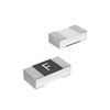
SF-0603F100-2
Bourns Inc.
FUSE BOARD MOUNT 1A 32VDC 0603
GRM1555C1H181JA01J
Murata Electronics
CAP CER 180PF 50V C0G/NP0 0402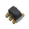
RFXF8553-TR13
RFMD
SMT TRANSFORMER 500MHZ-2.5GHZ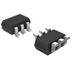
UPC8179TB-E3-A
CEL
IC RF AMP GPS 100MHZ-2.4GHZ 6SO
XC3064A-7PC84C
AMD
IC FPGA 70 I/O 84PLCC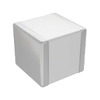
AQ147M101JAJME
KYOCERA AVX
CAP CER 100PF 500V 1111