T Trigger Knowledge Guide - Pros and Cons, How It Works, Types
Catalog
How T-Flip-Flops Work
Types of T-Flip-Flops
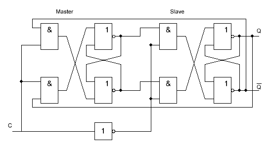
Synchronous T-Trigger
- Output condition: Here, both Gate1 and Gate2 are AND gates connected to T (set to 0).
- Gate1 and Gate2 output: Since an AND gate outputs 0 when any of its inputs are 0, the outputs of Gate1 and Gate2 will always be 0, regardless of their other inputs.
- Gate3/Q(n+1) logic: Gate3 is influenced by the output of Gate1. When Gate1 outputs 0, Gate3’s logic equation simplifies to NOT (0 OR NOT Q), resulting in Q.
- Gate4/Q(n+1)' logic: Gate4 follows a similar pattern, producing NOT (0 OR Q), simplifying to NOT Q or Q'.
- Assuming Gate1 = 0 and Gate2 = 0, and utilizing the characteristic of AND gates (any input of 0 results in an output of 0), the operation is straightforward:
- Gate3/Q(n+1) computes as Q, maintaining the current state.
- Gate4/Q(n+1)' results in Q', the complement of the current state.
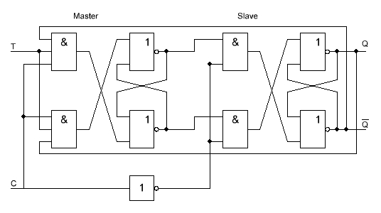
- Output condition: When T is set to 1, the inputs of Gate1 and Gate2 now reflect the outputs of other logic operations, influencing their outputs.
- Gate1 and Gate2 output: Gate1 connects directly to the current state Q, and Gate2 to NOT Q or Q'.
- Gate4/Q(n+1)' logic: Here, the equation simplifies because the inputs of the AND gate are opposites (Q and NOT Q), resulting in 0.
- Gate3/Q(n+1) logic: On the other hand, Gate3 deals with NOT Q or Q', outputting NOT (Q AND 0), simplifying to NOT Q or Q'.
- The logic setup leads to interesting interactions:
- Gate1=Q, Gate2=Q', affecting subsequent logic processes.
- Gate4/Q(n+1)' directly computes as 0, since the AND operation between Q and NOT Q cannot be true.
- Gate3/Q(n+1) then computes as Q', which is the toggle from the previous state when T was 0.
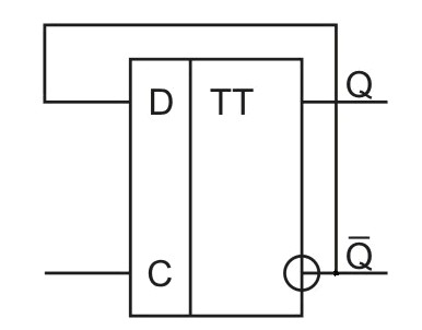
T Flip-Flop Truth Table
|
CLK |
T |
Q(n+1) |
State |
|
|
0 |
Q |
NO CHANGE |
|
|
1 |
Q’ |
TOGGLE |
|
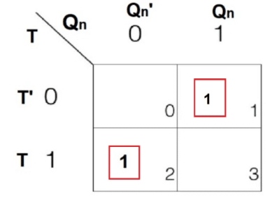
T |
Qn |
Q(n+1) |
|
0 |
0 |
0 |
|
0 |
1 |
1 |
|
1 |
0 |
1 |
|
1 |
1 |
0 |
Advantages of Using T-Flip-Flops
- Single input simplicity: T-flip-flops have only one input, simplifying their operation. This single input can toggle between high and low states, allowing it to seamlessly integrate into circuit designs and easily connect with other digital circuits.
- No invalid states: T-flip-flops lack invalid states, helping to prevent unpredictable behavior in digital systems. This reliability is crucial for maintaining consistent system performance.
- Reduced power consumption: Compared to other flip-flops, T-flip-flops consume less power. This energy efficiency is beneficial for extending the battery life of portable devices and reducing the energy costs of large digital systems.
- Bistable operation: Like other flip-flops, T-flip-flops feature bistable operation, meaning they can indefinitely hold either state (0 or 1) until triggered by an input signal. This characteristic is essential for applications that require stable, long-term storage of single-bit data.
- Easy implementation: T-flip-flops can be easily implemented using basic logic gates. This simplicity makes them an economically viable choice for many digital systems, helping to reduce overall system costs.
Limitations of T-Flip-Flops
- Inverted output: The output of T-flip-flops is the opposite of its input, which can complicate the design of timing logic circuits and make the design more complex. Designers need to consider this to ensure correct circuit behavior.
- Limited functionality: T-flip-flops can only store one bit of information and are not capable of performing complex operations like addition or multiplication, limiting their use in basic memory tasks.
- Sensitivity to glitches: T-flip-flops may be sensitive to glitches and noise on the input signal, potentially causing unexpected state changes. This sensitivity can lead to unpredictable behavior in digital systems, especially in environments with high electronic interference.
- Propagation delay: Like all flip-flops, T-flip-flops encounter propagation delays, which may introduce timing issues in systems with strict timing constraints. These delays must be considered during system design to avoid timing errors and ensure reliable operation.
Applications
- Frequency division: T-flip-flops are often used to halve the frequency of a clock signal. By toggling the state of the flip-flop with each clock pulse, they effectively divide the frequency of the input signal by two, making them ideal for precise timing and digital clocks and frequency synthesizers.
- Frequency doubling: Conversely, T-flip-flops can also be used to double the frequency of a clock signal, known as frequency doubling. This is achieved by configuring the flip-flops in a setup that generates an output frequency twice that of the input signal.
- Data storage: T-flip-flops can be used as basic building blocks for storing single data bits, where data needs to be temporarily saved for further processing or transmission. This makes them very useful in applications such as shift registers and storage devices.
- Counters: Another significant application of T-flip-flops is creating binary counters. They can be interconnected with other digital logic gates to construct counters that can increment or decrement counting based on design requirements.
About us
ALLELCO LIMITED
Read more
Quick inquiry
Please send an inquiry, we will respond immediately.

How Much Do You Know About CCA?
on April 26th
1.5V Battery —— How Much Do You Know?
on April 25th
Popular Posts
-

What is GND in the circuit?
on January 1th 3272
-

RJ-45 Connector Guide: RJ-45 Connector Color Codes, Wiring Schemes, R-J45 Applications, RJ-45 Datasheets
on January 1th 2815
-

Understanding Power Supply Voltages in Electronics VCC, VDD, VEE, VSS, and GND
on November 20th 2640
-

Fiber Connector Types: SC Vs LC And LC Vs MTP
on January 1th 2265
-

Comparison Between DB9 and RS232
on January 1th 1882
-

What Is An LR44 Battery?
Electricity, that ubiquitous force, quietly permeates every aspect of our daily lives, from trivial gadgets to life-threatening medical equipment, it plays a silent role. However, truly grasping this energy, especially how to store and efficiently output it, is no easy task. It is against this background that this article will focus on a type of coin cell battery that may seem insignificant on the...on January 1th 1846
-

Understanding the Fundamentals:Inductance Resistance, andCapacitance
In the intricate dance of electrical engineering, a trio of fundamental elements takes center stage: inductance, resistance, and capacitance. Each bears unique traits that dictate the dynamic rhythms of electronic circuits. Here, we embark on a journey to decipher the complexities of these components, to uncover their distinct roles and practical uses within the vast electrical orchestra. Inductan...on January 1th 1808
-

What Is RF and Why Do We Use It?
Radio Frequency (RF) technology is a key part of modern wireless communication, enabling data transmission over long distances without physical connections. This article delves into the basics of RF, explaining how electromagnetic radiation (EMR) makes RF communication possible. We will explore the principles of EMR, the creation and control of RF signals, and their wide-ranging uses. The article ...on January 1th 1801
-

CR2430 Battery Comprehensive Guide: Specifications, Applications and Comparison to CR2032 Batteries
What is CR2430 battery ?Benefits of CR2430 BatteriesNormCR2430 Battery ApplicationsCR2430 EquivalentCR2430 VS CR2032Battery CR2430 SizeWhat to look for when buying the CR2430 and equivalentsData Sheet PDFFrequently Asked Questions Batteries are the heart of small electronic devices. Among the many types available, coin cells play a crucial role, commonly found in calculators, remote controls, and ...on January 1th 1799
-

Comprehensive guide to hFE in transistors
Transistors are crucial components in modern electronic devices, enabling signal amplification and control. This article delves into the knowledge surrounding hFE, including how to select a transistor's hFE value, how to find hFE, and the gain of different types of transistors. Through our exploration of hFE, we gain a deeper understanding of how transistors work and their role in electronic circu...on November 20th 1782
HOT Part Number
-
SD3114-4R7-R
Eaton - Electronics Division
FIXED IND 4.7UH 770MA 251MOHM SM
400BXC22MEFC12.5X20
Rubycon
CAP ALUM 22UF 20% 400V RADIAL
NCP606MNADJT2G
onsemi
IC REG LINEAR POS ADJ 500MA 6DFN
C22G100
Eaton - Bussmann Electrical Division
FUSE CARTRIDGE 100A 500VAC
TA48S05AF(T6L1,Q)
Toshiba Semiconductor and Storage
IC REG LINEAR 5V 1A 5HSIP
EMK212F225ZG-T
Taiyo Yuden
CAP CER 2.2UF 16V Y5V 0805
CSD83325L
Texas Instruments
MOSFET 2N-CH 12V 6PICOSTAR
SN74LS47N
Texas Instruments
IC DRVR 7 SEGMENT 16DIP
ZXMN6A08GTA
Diodes Incorporated
MOSFET N-CH 60V 3.8A SOT223
VS-45L40
Vishay General Semiconductor - Diodes Division
DIODE GEN PURP 400V 150A DO205AC
LT3744EUHE#PBF
Analog Devices Inc.
IC LED DRIVER CTRLR PWM 36QFN
ICL3241ECVZ-T
Renesas Electronics America Inc
IC TRANSCEIVER FULL 3/5 28TSSOP
PS4066ACSDE
Diodes Incorporated
IC SWITCH SPST-NOX4 45OHM 14SOIC
BQ8055DBTR
Texas Instruments
PROTOTYPE
RT9078-12GQZ
Richtek USA Inc.
IC REG LINEAR 1.2V 300MA 4ZQFN
ACS710KLATR-6BB-T
Allegro MicroSystems
SENSOR CURRENT HALL 6A AC/DC
MC14569BDWR2
onsemi
IC DIVIDER BY N DL 4BIT 16SOIC
LED1642GWTTR
STMicroelectronics
IC LED DRVR LIN PWM 40MA 24TSSOP -

LM5110-1SDX
Texas Instruments
IC GATE DRVR LOW-SIDE 10WSON
1734101-7
TE Connectivity AMP Connectors
CONN BTB RCPT 68POS VERT SOLDER
MPC8555EVTAJD
Freescale Semiconductor
POWERQUICC RISC MICROPROCESSOR,
S-1167A33-M5T1G
ABLIC Inc.
IC REG LINEAR 3.3V 150MA SOT23-5
LQM2HPN1R0MJHL
Murata Electronics
FIXED IND 1UH 2.3A 63 MOHM SMD
AM1806BZCEA3
Texas Instruments
IC MPU SITARA 375MHZ 361NFBGA
MPZ1005S300CT000
TDK Corporation
FERRITE BEAD 30 OHM 0402 1LN
GRM1887U1H7R9DZ01D
Murata Electronics
CAP CER 7.9PF 50V U2J 0603
BCM59111KMLG
Broadcom Limited
IC POE CNTRL 4 CHANNEL 48QFN
MAX211CWI+T
Analog Devices Inc./Maxim Integrated
IC TRANSCEIVER FULL 4/5 28SOIC
ISL80101IRAJZ-T
Renesas Electronics America Inc
IC REG LINEAR POS ADJ 1A 10DFN
APX809S00-44SR-7
Diodes Incorporated
IC SUPERVISOR 1 CHANNEL SOT23
IS43LR16640A-6BL
ISSI, Integrated Silicon Solution Inc
IC DRAM 1GBIT PARALLEL 60TWBGA
EVK105RH0R6BW-F
Taiyo Yuden
CAP CER 0.6PF 16V R2H 0402
GRM3166T1H100JD01D
Murata Electronics
CAP CER 10PF 50V T2H 1206
GRM32ER61A106MA01K
Murata Electronics
CAP CER 10UF 10V X5R 1210
AOB4184
Alpha & Omega Semiconductor Inc.
MOSFET N-CH 40V 12A/50A TO263
LP3872EMPX-2.5
Texas Instruments
IC REG LINEAR 2.5V 1.5A SOT223-5 -
CRCW06033R90FKEA
Vishay Dale
RES SMD 3.9 OHM 1% 1/10W 0603
DS1245YP-100+
Analog Devices Inc./Maxim Integrated
IC NVSRAM 1MBIT PAR 34PWRCAP
LDK320AM36R
STMicroelectronics
IC REG LINEAR 3.6V 200MA SOT23-5
AON6403
Alpha & Omega Semiconductor Inc.
MOSFET P-CH 30V 21A/85A 8DFN
LTC2934CTS8-2#TRPBF
Analog Devices Inc.
IC SUPERVISOR 1 CHANNEL TSOT23-8
P91E0-I5NHGI8
Renesas Electronics America Inc
VFQFPN 9.00X9.00X0.85 MM, 0.50MM
GRM1887U2A7R6DZ01D
Murata Electronics
CAP CER 7.6PF 100V U2J 0603
R3112N421A-TR-FE
Nisshinbo Micro Devices Inc.
IC SUPERVISOR 1 CHANNEL SOT23-5
IXGH36N60A3D4
IXYS
IGBT 600V 220W TO247
LT1007CH
Analog Devices Inc.
IC OPAMP GP 1 CIRCUIT TO5
CRCW1206510KJNEA
Vishay Dale
RES SMD 510K OHM 5% 1/4W 1206
BU25UA3WNVX-TL
Rohm Semiconductor
IC REG LIN 2.5V 300MA 4SSON
ICS9P750CFLF
Renesas Electronics America Inc
IC CLK BUFFER DDR PLL ZD 48-SSOP
74479777310
Würth Elektronik
FIXED IND 10UH 650MA 625MOHM SMD
V300C3V3H50BL
Vicor Corporation
DC DC CONVERTER 3.3V 50W
HMC370LP4ETR
Analog Devices Inc.
IC X4 ACTIVE MULTIPLIER 24-QFN
XR16M2551IL32TR-F
MaxLinear, Inc.
IC UART FIFO 16B DUAL 32QFN
ECLAMP2384P.TCT
Semtech Corporation
FILTER RC(PI) 200 OHM/12PF SMD