How to Use an Ammeter to Measure Current?
Accurately measuring electrical current is needed in the fields of electrical engineering and electronics for understanding and troubleshooting circuits. The ammeter, a specialized instrument designed for this purpose, best in both educational and professional contexts. This article serves as a thorough guide on using an ammeter to measure current, covering the principles of electrical current, the operational mechanics of ammeters, and practical techniques for precise measurements. Beginning with the fundamentals of electrical current and Ohm's Law, it progresses to the working principle of ammeters, highlighting their low resistance and series connection in circuits. The article discusses the components and tools for building basic electrical circuits. Advanced topics such as the differences between ammeters and multimeters, and safety mechanisms like fuses in ammeters, are also explored to provide users with the knowledge to handle these instruments safely and effectively. Through detailed explanations and practical examples, this article aims to enhance your proficiency in current measurement, making it a valuable resource for anyone involved in electrical diagnostics and maintenance.
Catalog
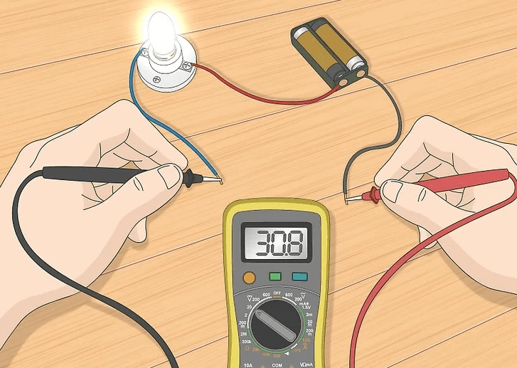
Figure 1: Digital Ammeter Measure Current
Understanding Electrical Current
Electrical current is the movement of electrons through a circuit, measured in amperes (A), or "amps." It's a main idea in electricity and electronics, helping us understand how electrical systems work. Current is an important part of Ohm’s Law, an equation used by electrical engineers to diagnose and fix problems.
Ohm’s Law is simply written as V = I × R, where:
V is voltage, the difference in electrical potential between two points in a circuit.
I is current, the speed at which electrons flow through the circuit.
R is resistance, which is how much the circuit resists the flow of current.
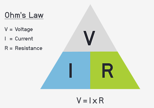
Figure 2: Ohm's Law Triangular Equation
Ammeter Reading and Symbol
An ammeter is an instrument used to measure the flow of electric current, which is quantified in units called amperes. When an ammeter is used in an electrical circuit, it provides a reading in these amperes to indicate the current's magnitude. In circuit diagrams, an ammeter is symbolized by the letter 'A' enclosed within a small circle, making it easily identifiable within the schematic. This representation helps in understanding and analyzing the behavior of the electrical circuit by clearly indicating where the current measurement takes place.
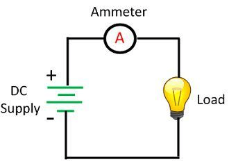
Figure 3: Ammeter Reading and Symbol
Working Principle of an Ammeter
An ammeter measures current by having very low resistance and minimal inductive reactance. This ensures it doesn't change the circuit's behavior, allowing accurate current measurement. Its low resistance means the voltage drop across it is tiny, preserving the current flow and enabling precise readings.
The ammeter is placed in series with the circuit to measure the entire current flowing through it. Inside the ammeter, a small resistor called a shunt allows some current to pass through it. This creates a minor voltage drop proportional to the current, which is easier to measure. Using Ohm's Law (I = V/R), the ammeter calculates the current from this voltage drop.
The shunt allows the ammeter to measure large currents accurately without damage. The voltage drop across the shunt increases with the current, which the ammeter converts into a readable value. The ammeter measures the small voltage drop across the shunt, converts it to current, and displays it.
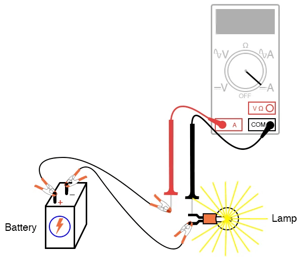
Figure 4: Ammeter test probe connections for measuring current
Components and Tools for Building a Basic Electrical Circuit
Here are the components to build a basic electrical circuit. The main materials include:
6 V battery: The power source for your circuit.
6 V incandescent lamp: The load to demonstrate current flow.
Breadboard: A reusable platform for constructing circuits.
Terminal strip: For connecting and organizing wires.
Jumper wires: To connect components on the breadboard.
These basic components will facilitate a hands-on introduction to circuit construction and current measurement, allowing you to focus on mastering the core principles and techniques of using an ammeter effectively without the need for specialized equipment.
Techniques for Accurate Current Measurement Using Ammeters
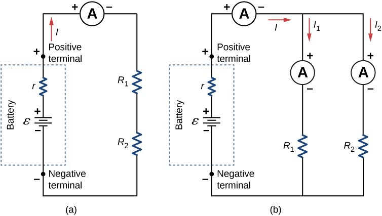
Figure 5: Measuring Current
(a) To measure the current through two resistors connected in series to a battery, a single ammeter is placed in series with the two resistors. This is because the current remains consistent through both resistors in a series circuit.
(b) In contrast, when two resistors are connected in parallel with a battery, three separate ammeter readings are required to measure the current from the battery and through each individual resistor. Each ammeter is connected in series with the specific component being measured.
Measuring electrical current involves quantifying the flow of electrons through a circuit, which is expressed in amperes (amps, A). The standard method involves placing an ammeter in series with the circuit. This setup ensures that all electrons flow through the meter, providing an accurate measurement of the current. This method differs from measuring voltage or resistance, which can be done with the meter connected in parallel to the circuit.
A key aspect of current measurement is understanding that the ammeter must be integrated directly into the circuit. This can be challenging if not done correctly. Modern digital multimeters, like the one shown in Figure 4, typically have a dedicated A jack for the red test lead, specifically for current measurements. This setup is different from many inexpensive analog meters that use the same jacks for all types of measurements. It’s should consult first your meter’s manual to understand the specific procedures for current measurement with your device.
When properly connected, an ammeter should present negligible resistance, functioning almost like a wire, ensuring it doesn't alter the circuit while measuring current. Incorrect connections can lead to measurement errors or even damage to the circuit and the meter, so it is need to follow correct procedures to maintain both safety and measurement accuracy.
Ammeter Fuses for High Current Protection
Ammeters have low internal resistance, so incorrect connections can lead to dangerous situations like short circuits, particularly if the ammeter is connected in parallel with a much voltage source. This can cause a sudden surge of current that may damage the meter, as shown in Figure below. To prevent such occurrences, ammeters include a small fuse within the meter housing. This fuse is designed to blow if an excessive current flows through the meter, thereby protecting the device from damage.
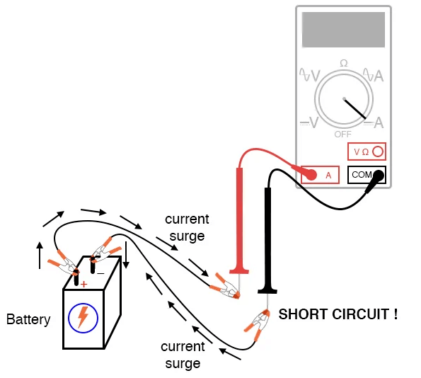
Figure 6: Ammeter Short Circuit Connection Resulting in a Surge Current
To check a multimeter’s fuse, set the meter to resistance mode and measure continuity through the test leads and the fuse. If your meter uses different jacks for current measurements, insert the test lead plugs accordingly, as shown in Figure below.

Figure 7: Testing An Ammeter's Fuse
For meters using the same jacks for resistance and current measurements, touch the two probes together while keeping the lead plugs in place. Construct a basic circuit using a 6 V battery and a lamp, connecting them with jumper wires.
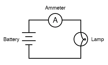
Figure 8: Diagram for Measuring the Current of the Lamp Circuit Using Ammeter
Before integrating the ammeter, ensure the lamp lights up. Then, break the circuit, and insert the ammeter’s test probes into the circuit break to measure the current. If your meter has a manual range, start with the highest range and gradually decrease it until the meter displays a reading without over-ranging. If the reading appears reversed (left motion on an analog needle or negative on a digital display), switch the test probes and try again.
For a typical 6 V battery and a small lamp, the current is expected to be in the milliampere (mA) range. Digital meters often display a small “m” to indicate milliamps. Experiment with different circuit break points to measure current and observe how the current changes. This will deepen your understanding of circuit behavior.
How to Connect an Ammeter to a Breadboard Circuit?
To reconstruct the circuit on a breadboard, as shown in Figure below.
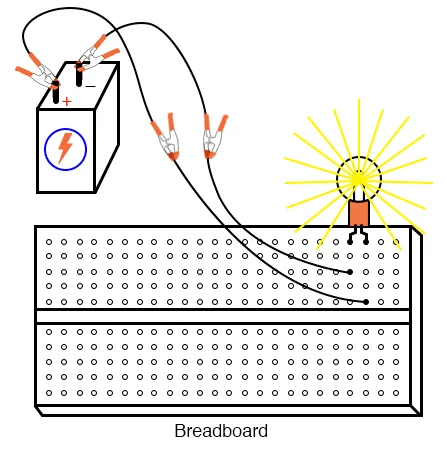
Figure 9: Breadboard Implementation of the Lamp Circuit
Follow these steps to ensure accurate current measurement without creating a short circuit:
Identify the Current Path: Find the wire or terminal through which you wish to measure current;
Break the Circuit: Remove the wire from the breadboard and insert a spare wire into the now-empty hole;
Connect the Ammeter: Insert the ammeter between the two disconnected wire ends;
Verify Connections: Ensure the new circuit mirrors the image in Figure below. The indicated current of 24.70 milliamps (24.70 mA) is a reasonable value for a small incandescent lamp.

Figure 10: Breadboard Implementation of the Lamp Circuit with An Ammeter Measuring Current
If the lamp does not light up and the ammeter shows a high reading, a short-circuit condition might exist. If the ammeter displays zero current, the internal fuse may be blown, necessitating an inspection and replacement. Measure current through different wires in the circuit following the same connection procedure. Compare these measurements with those from the free-form circuit to ensure consistency, reinforcing your understanding of current measurement and circuit behavior. Finally, construct the same lamp circuit on a terminal strip as shown in Figure below.
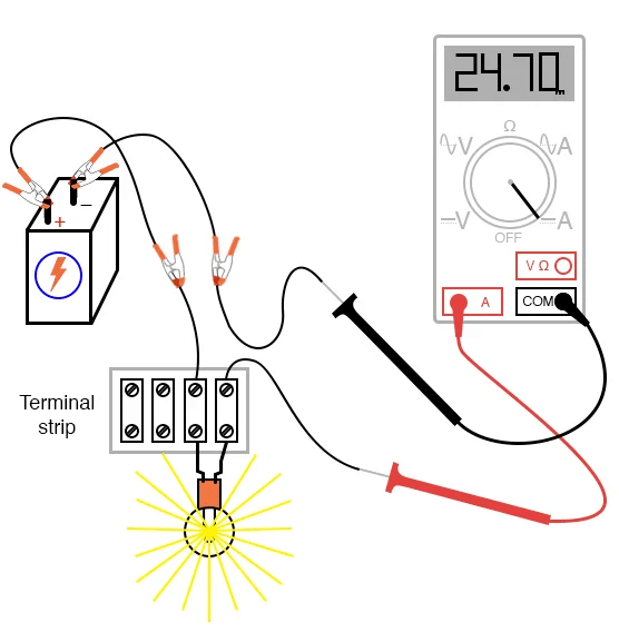
Figure 11: Terminal Strip Implementation of the Lamp Circuit with An Ammeter Measuring Current
Measure the current and compare it with previous results to ensure consistency across different configurations. This step solidifies your understanding and competence in using an ammeter for electrical diagnostics, reinforcing the practical application of current measurement techniques. Mastering these skills is great for effective troubleshooting and maintenance of electrical systems, making this project a valuable part of your electrical education.
Differences Between Ammeters and Multimeters
|
Aspect |
Ammeters |
Multimeters |
|
Primary Function |
Measures electric current only. |
Measures current, voltage, resistance, and sometimes capacitance and frequency. |
|
Application |
Used for tasks requiring precise current measurements. |
Used for diagnosing and troubleshooting a variety of electrical parameters. |
|
Connection |
Connected in series with the circuit. |
Connected in parallel for voltage or resistance; in series for current. |
|
Impact on Circuit |
Low resistance, minimal alteration of current. |
Varies; more impact than ammeters due to higher internal resistance. |
|
Measurement Type |
Current (AC or DC). |
Current (AC/DC), voltage (AC/DC), resistance, continuity, and more. |
|
Display Type |
Often analog, sometimes digital. |
Predominantly digital with clear, immediate readings. |
|
Ease of Use |
Requires circuit interruption to connect. |
User-friendly interfaces, multifunctional, no circuit interruption needed for most measurements. |
|
Versatility |
Highly specialized, limited to current measurements. |
Versatile, can measure multiple parameters. |
|
Technological Features |
Limited features; focuses on current measurement accuracy. |
Digital display, data logging, connectivity for advanced analysis. |
|
Data Handling |
Limited to direct readings. |
Supports data storage, logging, and transfer to computers for further analysis. |
|
Cost Efficiency |
Usually less expensive but limited in functionality. |
More cost-effective for multiple functions and comprehensive diagnostics. |
|
Ideal Use Case |
Tasks requiring exact current measurement without disturbing the circuit. |
General diagnostics, troubleshooting, and comprehensive system evaluation. |
Differences Between Ammeters and Voltmeters
|
Aspect |
Ammeters |
Voltmeters |
|
Primary Function |
Measures the current flowing through a circuit. |
Measures the voltage (potential difference) between two points in a circuit. |
|
Internal Resistance |
Very low, to avoid altering the current flow. |
Very high, to prevent current draw from the circuit. |
|
Connection Method |
Connected in series with the circuit. |
Connected in parallel with the points being measured. |
|
Measurement Range |
Fixed; requires different devices for varying current levels. |
Flexible; can measure a wide range of voltages by adjusting internal resistance. |
|
Accuracy |
High due to direct current measurement and minimal circuit interference. |
Varies; lower than ammeters due to indirect measurement and high internal resistance. |
|
Circuit Impact |
Minimal, as it introduces negligible resistance. |
Minimal, as it draws negligible current. |
|
Application |
Ideal for testing electrical components and diagnosing circuit issues with precise current needs. |
Ideal for checking voltage levels, diagnosing power supply issues, and ensuring proper operation of components. |
|
Design Consideration |
Requires low resistance to ensure accurate current measurement without impacting the circuit. |
Requires high resistance to accurately measure voltage without affecting the circuit. |
|
Common Usage |
Used to measure and monitor current, ensuring safety and functionality of circuits. |
Used to measure and monitor voltage, ensuring components are within their operational ranges. |
Differences Between Analog Ammeter and Digital Ammeter
|
Aspect |
Analog Ammeter |
Digital Ammeter |
|
Measurement Method |
Moving pointer sweeps across a scale to indicate current. |
Electronic circuitry converts analog signal to a digital display. |
|
Scale Type |
Linear or non-linear, depending on DC or AC measurement. |
Digital readout in amps, with precision defined by display digits. |
|
Scale Interpretation |
DC: Linear scales with equally spaced divisions.<br>AC: Non-linear scales with unevenly spaced divisions. |
Clear, straightforward readings with no interpretation needed. |
|
Operational Principle |
Electromagnetic principles: current generates a magnetic field that moves the pointer. |
Electronic conversion of current signal to digital format. |
|
Power Source |
Does not require a power source for operation. |
Requires a power source for electronic circuitry. |
|
Accuracy and Precision |
Dependent on user's ability to interpret pointer position. |
High precision, eliminates human error in reading. |
|
Advanced Features |
Simplicity and reliability; ideal for quick, glance-based readings. |
Data logging for recording over time, auto-ranging, overload protection, and connectivity options. |
|
User Interface |
Direct visual indication of current; straightforward and easy to read. |
User-friendly interfaces, often with backlit displays. |
|
Application Suitability |
Suitable for quick readings in various conditions without needing a power source. |
Suitable for precise measurements in a wide range of applications, from household to industrial environments. |
|
Functionality Enhancement |
None |
Can integrate with software for real-time monitoring and data analysis. |

Figure 12: Analog Ammeter
Figure 13: Digital Ammeter
Applications of an Ammeter
Ammeters are useful in both homes and industries, especially in managing electrical current flow. These devices ensure electrical systems function efficiently and safely. Whether checking home wiring or optimizing renewable energy setups, ammeters monitor and manage current flow.
Home Wiring: Ammeters are needed in home wiring to ensure household electrical systems work correctly. They measure current flow through circuits, helping to identify issues like overloaded circuits. Detecting these problems early helps prevent electrical hazards, including fires. Homeowners can use ammeters to confirm that electrical installations meet safety standards and can handle modern appliances. Ammeters provide peace of mind by ensuring home electrical systems are safe and efficient.
Gadget Performance: Ammeters provide valuable insights into the power consumption of many devices. When connected to appliances like computers and refrigerators, they reveal the current each device draws. This information helps in understanding energy usage and making informed decisions about energy conservation. Identifying power-hungry devices can lead to replacing them with more energy-efficient models, reducing energy bills, and lowering carbon footprints.
Car Troubleshooting: Ammeters are important in car troubleshooting, especially for diagnosing battery and alternator issues. By measuring current flow, they determine if these components work properly. An imbalance in current flow can signal problems like a failing alternator or weak battery.
Industrial Applications: In industrial settings, ammeters oversee currents powering heavy machinery. Factories and manufacturing plants rely on ammeters to monitor electrical systems, ensuring machinery runs smoothly and efficiently. By detecting early signs of electrical issues, ammeters help in timely maintenance and repairs, enhancing productivity and safety.
Renewable Energy Systems: In systems using solar panels and wind turbines, ammeters monitor and optimize current flow. These energy sources can be unpredictable, making accurate current measurement required. Ammeters help balance the load, prevent overloading, and ensure efficient energy use.
Electronics Creation: In electronics creation, ammeters are a must for adjusting parts and making sure they use the proper amount of current. A correct current measurement during the design and development of electronic devices is best for optimizing performance and reliability. Ammeters help engineers calibrate circuits accurately, ensuring each component operates within its specified current range.
Conclusion
Mastering the use of an ammeter to measure current is important skill for both novice and experienced electricians and engineers. It has offered an in-depth examination of any aspects of using an ammeter, from understanding basic principles of electrical current to the practical steps of incorporating the ammeter into different circuit configurations. By detailing the operational principles of ammeters, including their low resistance and series connection, and comparing them with multimeters and voltmeters, we have highlighted the importance of choosing the right tool for precise measurements. The inclusion of safety measures, such as using fuses to prevent damage from high current surges, ensures that users can operate ammeters without risking equipment or personal safety. The article's practical approach, featuring step-by-step instructions for constructing circuits and measuring current, reinforces theoretical knowledge with hands-on application. Whether for home wiring, industrial machinery, renewable energy systems, or electronics creation, the ammeter remains a major tool. This comprehensive guide aims to empower a confidence and expertise to accurately measure electrical current, ultimately contributing to better-designed and safer electrical systems.
Frequently Asked Questions [FAQ]
1. How do you measure the presence of current?
To measure the presence of current, you use a device called an ammeter. Here's a step-by-step guide on how to do it:
Turn Off the Circuit: Before connecting the ammeter, ensure the circuit is powered off to avoid any accidents or damage.
Open the Circuit: Identify where you need to measure the current and open the circuit at that point.
Connect the Ammeter: Connect the ammeter in series with the circuit. This means you insert the ammeter into the circuit path so that the current flows through it.
Turn On the Circuit: Power on the circuit. The ammeter will display the current flowing through the circuit.
2. How does an ammeter work?
An ammeter works by measuring the flow of electric charge through a conductor. Here’s a simplified explanation:
Internal Resistance: An ammeter has very low internal resistance to ensure it does not alter the current it is measuring.
Electromagnetic Interaction: Inside the ammeter, the current generates a magnetic field that interacts with a coil or a needle, causing it to move.
Scale Display: The movement of the needle or the digital display corresponds to the amount of current flowing through the ammeter, which is then read off a calibrated scale.
3. What are the three uses of an ammeter?
Measuring Circuit Current: To determine how much current is flowing through different parts of a circuit.
Testing Components: To check the current consumption of individual components, ensuring they are functioning within their specified limits.
Diagnosing Electrical Problems: To find faults in electrical systems by identifying unexpected current values, indicating issues like short circuits or faulty components.
4. How to check if an ammeter is working or not?
To check if an ammeter is working, follow these steps:
Visual Inspection: Check for any visible signs of damage on the ammeter, such as broken wires or a damaged display.
Battery Test: If the ammeter is portable and battery-operated, ensure the battery is charged and properly installed.
Known Current Source: Connect the ammeter to a known current source. If it displays the expected value, it is working correctly.
Continuity Test: Use a multimeter to check for continuity in the ammeter’s connections. A break in the circuit will indicate a malfunction.
5. How to place an ammeter in a circuit?
To place an ammeter in a circuit correctly:
Turn Off Power: Always start by turning off the power to the circuit.
Identify Measurement Point: Determine where you need to measure the current.
Break the Circuit: Open the circuit at the measurement point.
Connect Ammeter in Series: Connect the ammeter leads to the two open ends of the circuit, ensuring it is in series. The current must flow through the ammeter.
Secure Connections: Ensure all connections are secure and insulated properly.
Turn On Power: Restore power to the circuit and observe the ammeter reading.
6. Why is my ammeter not working?
If your ammeter is not working, consider these potential issues:
Blown Fuse: Many ammeters have an internal fuse to protect against overcurrent. Check if this fuse is blown and replace it if needed.
Incorrect Connection: Ensure the ammeter is connected in series with the circuit and not in parallel. Incorrect connections can prevent it from measuring current.
Internal Damage: The ammeter might have internal damage from previous overcurrent or mechanical shock. A professional inspection or replacement might be needed.
Dead Battery: If it is a battery-operated ammeter, check if the battery needs replacing.
Open Circuit: Ensure the circuit itself is complete and that there is a current flow to measure. An open circuit or faulty component elsewhere can affect the measurement.
electrical current, ammeter, Ohm's Law, electrical circuit, current measurement, fuses, breadboard, multimeter, voltmeter, digital ammeter, analog ammeter, circuit diagnostics, electrical troubleshooting, renewable energy systems, circuit protection, electrical safety, power consumption, automotive electrical testing, industrial electrical applications, energy efficiency, electrical maintenance, electrical engineering
About us
ALLELCO LIMITED
Read more
Quick inquiry
Please send an inquiry, we will respond immediately.
The Impact of Harmonics on Electrical Systems
on June 25th
Exploring the Rectification Properties of PN Junctions
on June 24th
Popular Posts
-

What is GND in the circuit?
on January 1th 2937
-

RJ-45 Connector Guide: RJ-45 Connector Color Codes, Wiring Schemes, R-J45 Applications, RJ-45 Datasheets
on January 1th 2498
-

Fiber Connector Types: SC Vs LC And LC Vs MTP
on January 1th 2089
-

Understanding Power Supply Voltages in Electronics VCC, VDD, VEE, VSS, and GND
on November 9th 1888
-

Comparison Between DB9 and RS232
on January 1th 1760
-

What Is An LR44 Battery?
Electricity, that ubiquitous force, quietly permeates every aspect of our daily lives, from trivial gadgets to life-threatening medical equipment, it plays a silent role. However, truly grasping this energy, especially how to store and efficiently output it, is no easy task. It is against this background that this article will focus on a type of coin cell battery that may seem insignificant on the...on January 1th 1712
-

Understanding the Fundamentals:Inductance Resistance, andCapacitance
In the intricate dance of electrical engineering, a trio of fundamental elements takes center stage: inductance, resistance, and capacitance. Each bears unique traits that dictate the dynamic rhythms of electronic circuits. Here, we embark on a journey to decipher the complexities of these components, to uncover their distinct roles and practical uses within the vast electrical orchestra. Inductan...on January 1th 1651
-

CR2430 Battery Comprehensive Guide: Specifications, Applications and Comparison to CR2032 Batteries
What is CR2430 battery ?Benefits of CR2430 BatteriesNormCR2430 Battery ApplicationsCR2430 EquivalentCR2430 VS CR2032Battery CR2430 SizeWhat to look for when buying the CR2430 and equivalentsData Sheet PDFFrequently Asked Questions Batteries are the heart of small electronic devices. Among the many types available, coin cells play a crucial role, commonly found in calculators, remote controls, and ...on January 1th 1548
-

What Is RF and Why Do We Use It?
Radio Frequency (RF) technology is a key part of modern wireless communication, enabling data transmission over long distances without physical connections. This article delves into the basics of RF, explaining how electromagnetic radiation (EMR) makes RF communication possible. We will explore the principles of EMR, the creation and control of RF signals, and their wide-ranging uses. The article ...on January 1th 1537
-

CR2450 vs CR2032: Can The Battery Be Used Instead?
Lithium manganese batteries do have some similarities with other lithium batteries. High energy density and long service life are the characteristics they have in common. This kind of battery has won the trust and favor of many consumers because of its unique safety. Expensive tech gadgets? Small appliances in our homes? Look around and you'll see them everywhere. Among these many lithium-manganes...on January 1th 1505
HOT Part Number
-

NL17SG125DFT2G
onsemi
IC BUFFER NON-INVERT 3.6V SC88A
BM25U-4P/2-V(51)
Hirose Electric Co Ltd
CONN HDR
CY8C20234-12SXIT
Infineon Technologies
IC MCU 8BIT 8KB FLASH 16SOIC
MAX321ESA+
Analog Devices Inc./Maxim Integrated
IC SWITCH SPST-NCX2 35OHM 8SOIC
SS3H10-E3/57T
Vishay General Semiconductor - Diodes Division
DIODE SCHOTTKY 100V 3A DO214AB
ISL34321INZ
Renesas Electronics America Inc
IC SER/DESER LVDS SERDES 48TQFP
AAT3221IJS-1.8-T1
Skyworks Solutions Inc.
IC REG LINEAR 1.8V 150MA 8SC70JW
1206GC331KAT1AJ
KYOCERA AVX
CAP CER 330PF 2KV X7R 1206
JANTX1N1206A
Microchip Technology
DIODE GEN PURP 600V 12A DO203AA
MK02FN64VLF10
NXP USA Inc.
IC MCU 32BIT 64KB FLASH 48LQFP
LTC201ACS#PBF
Analog Devices Inc.
IC SWITCH SPST-NCX4 125OHM 16SO
MAX9277GTM/V+
Analog Devices Inc./Maxim Integrated
IC DESERIALIZ GMSL 3.12GBPS 48TQ
AD8671ARZ-REEL
Analog Devices Inc.
IC OPAMP GP 1 CIRCUIT 8SOIC
STGIPQ5C60T-HL
STMicroelectronics
SLLIMM NANO 2ND SERIES IPM, 3-PH
TPS62021DRCR
Texas Instruments
IC REG BUCK ADJ 600MA 10VSON
VI-811717B
Vicor Corporation
H 150/350/300 5V/ 40A
12102U140JAT2A
KYOCERA AVX
CAP CER 14PF 200V NP0 1210
SDR1307-471KL
Bourns Inc.
FIXED IND 470UH 900MA 720MOHM SM -

ADS7887SDCKR
Texas Instruments
IC ADC 10BIT SAR SC70-6
FERD40L60CTS
STMicroelectronics
DIODE ARRAY 60V 20A TO220AB
R7201212XXOO
Powerex Inc.
DIODE GP 1.2KV 1200A DO200AB
LM5114BMFX/NOPB
Texas Instruments
IC GATE DRVR LOW-SIDE SOT23-6
UMK325LD105KN-T
Taiyo Yuden
CAP CER 1UF 50V X5R 1210
HDSP-F513
Broadcom Limited
DISPLAY 7SEG 0.4" SGL GRN 10DIP
EL4543IU
Intersil
DIFF TWISTED PAIR DRIVERS
OPA130UA/2K5
Texas Instruments
IC OPAMP GP 1 CIRCUIT 8SOIC
HFA15TB60PBF
International Rectifier
DIODE GEN PURP 600V 15A TO220AC
LTC1864CMS8#TRPBF
Analog Devices Inc.
IC ADC 16BIT SAR 8MSOP
ADP2165ACPZ-R7
Analog Devices Inc.
IC REG BUCK ADJ 5A 24LFCSP
APT50M75JLLU2
Microchip Technology
MOSFET N-CH 500V 51A SOT227
JW2SN-B-DC24V
Panasonic Electric Works
RELAY GEN PURPOSE DPDT 5A 24V
MM5Z22V
Fairchild Semiconductor
DIODE ZENER 22V 0.2W 5.67% UNI
US1A-13
Diodes Incorporated
DIODE GEN PURP 50V 1A SMA
TL145406N
Texas Instruments
IC TRANSCEIVER FULL 3/3 16DIP
STW7N105K5
STMicroelectronics
MOSFET N-CH 1050V 4A TO247
08051A680GAT4A
KYOCERA AVX
CAP CER 68PF 100V C0G/NP0 0805 -
TMS320LC203PZA
Texas Instruments
IC CMOS DSP 100LQFP
ADS7844NB/1K
Texas Instruments
IC ADC 12BIT SAR 20SSOP
FCH76N60N
Fairchild Semiconductor
POWER FIELD-EFFECT TRANSISTOR, 7
MRF8P26080HR3
NXP USA Inc.
FET RF 2CH 65V 2.62GHZ NI780-4
1N5934B
onsemi
DIODE ZENER 24V 3W AXIAL
VLS3015T-330MR36
TDK Corporation
FIXED IND 33UH 360MA 959MOHM SMD
1808HA150KAT1A
KYOCERA AVX
CAP CER 15PF 3KV C0G/NP0 1808
BA7809FP-E2
Rohm Semiconductor
IC REG LINEAR 9V 1A TO252-3
DSR8A600
Diodes Incorporated
DIODE GEN PURP 600V 8A TO220AC
GRM1555C1E3R0BZ01D
Murata Electronics
CAP CER 3PF 25V C0G/NP0 0402
TC07-11GWA
Kingbright
LED MATRIX 5X7 0.7" 565NM GN
0154.500DR
Littelfuse Inc.
FUSE BOARD MNT 500MA 125VAC/VDC
RS1MSP1-7
Diodes Incorporated
DIODE GP 1KV 1A POWERDI123
DEA162600BT-1258C2
TDK Corporation
RF FILTER BAND PASS 2.6GHZ 0603
Q2008LT
Littelfuse Inc.
TRIAC INT TRIGGER 200V 8A TO220
LM3S1512-IQC25-A2
Texas Instruments
IC MCU 32BIT 96KB FLASH 100LQFP
TPS65820RSHR
Texas Instruments
IC BATT MFUNC LI-ION 1CEL 56VQFN
MBR4060WT
Vishay General Semiconductor - Diodes Division
DIODE ARRAY SCHOTTKY 60V TO247AC