Exploring the Timeless Technology of Crystal Set Circuits
The crystal radio, an ideal symbol of early radio innovation, epitomizes the marvel of wireless communication in its simplest form. Historically rooted in the bedrock of radio technology, crystal radios have evolved from rudimentary experimental apparatuses to sophisticated devices embodying significant technological advancements.This article digs into the intricate details of crystal radio circuits, highlighting the key components and the evolution of their design to enhance performance. From the basic configurations employing end-fed wire antennas and simple diode detectors to complex designs incorporating input transformers and RF amplifiers, the development of crystal radio circuits illustrates a remarkable journey of technological refinement. This exploration not only sheds light on the operational principles of these devices but also underscores the continuous efforts to optimize signal reception and audio quality amidst inherent technical limitations.
Catalog
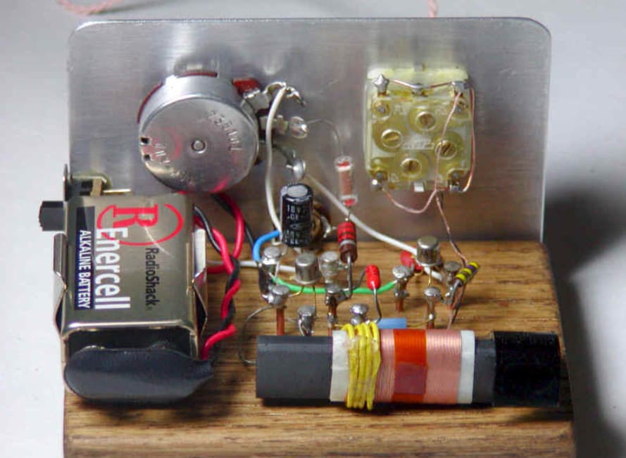
Figure 1: Elements of Crystal Radio Set Circuits
Exploring the Elements of Crystal Radio Set Circuits
Analyzing the components of a crystal radio set reveals the precise details that make these devices work efficiently. At the heart of a crystal radio's performance is the connection between the antenna and the grounding system. Most commonly, an external end-fed wire antenna is used. This antenna is particularly effective at capturing radio waves. When paired with a solid grounding system, it greatly improves the radio's ability to receive signals.
The design of the antenna system is used. A well-made antenna ensures that the crystal radio circuit works as efficiently as possible. The challenge lies in balancing simplicity with the technical limitations of early radio technology. Over time, these designs have evolved from basic experimental setups to more sophisticated systems. These refinements are aimed at maximizing the performance of crystal radios, even within their inherent limitations.
Antenna Coupling and Related Components in Crystal Radios
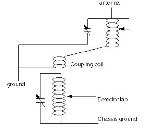
Figure 2: Antenna Coupling
When examining crystal radio designs, it's clear that antenna coupling plays a notable role in ensuring the radio functions properly. Different methods have been developed to connect the antenna effectively with the radio circuit. In simpler designs, the antenna is directly linked to the main tuning circuit. However, more advanced designs use impedance-matching techniques to boost performance. This often involves adding extra windings to the tuning inductor or using adjustable taps on the inductor itself.
A common approach is to create a resonant circuit that tunes the antenna to a quarter wavelength of the desired frequency. For medium wave frequencies, this typically requires about 150 feet of wire. However, adjusting the antenna length to match different frequencies can be difficult, especially in limited residential spaces. To overcome this, modern crystal radios often include antenna tuning circuits. These circuits adjust the antenna's impedance to match the rest of the radio circuit, improving signal resonance and overall reception.
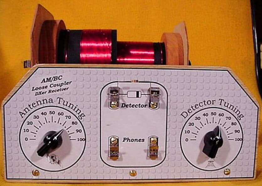
Figure 3: Main Tuning and Detector Coupling
The main tuning mechanism and detector coupling are dominant in enhancing a crystal radio's signal clarity and selectivity. The main tuning system, which is dynamic for amplifying the desired signals while filtering out others, usually involves capacitors. These capacitors might also interact with those used for antenna matching, adding complexity to the tuning process. To achieve optimal performance, designers must calculate precise values for inductors and capacitors to cover the intended frequency range. This calculation is based on standard resonance formulas, ensuring the radio resonates accurately at chosen frequencies. The careful balancing of technical precision with practical usability highlights the detailed engineering required in crystal radios.
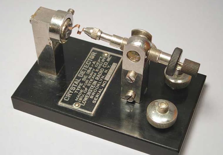
Figure 4: Signal Detector
The evolution of signal detectors in crystal radios mirrors the advancements in semiconductor technology. Early detectors, such as the Cat's Whisker, used a pointed wire contact on semiconductor materials, functioning like basic Schottky diodes. Modern detectors, like small-signal Schottky or germanium diodes, have lower activation voltages and are much better at detecting weak signals. This shift from primitive to more advanced detectors marks a significant improvement in radio technology, enabling the development of smaller and more reliable devices.
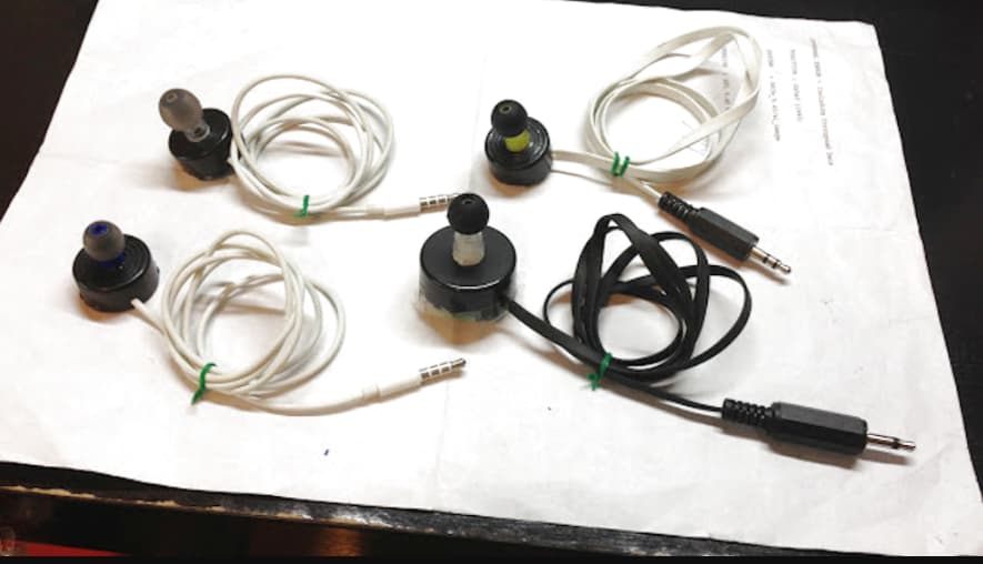
Figure 5: Earphones
High-impedance earphones are required for crystal radios, designed specifically to work with the radios' low power output. Traditional earphones used electromagnets and diaphragms to convert electrical signals into sound through magnetic fluctuations. Modern versions sometimes use piezoelectric crystals, which convert voltage into sound more efficiently and with less current. This change represents a move toward more energy-efficient audio technology, improving the overall performance and sustainability of these listening devices.
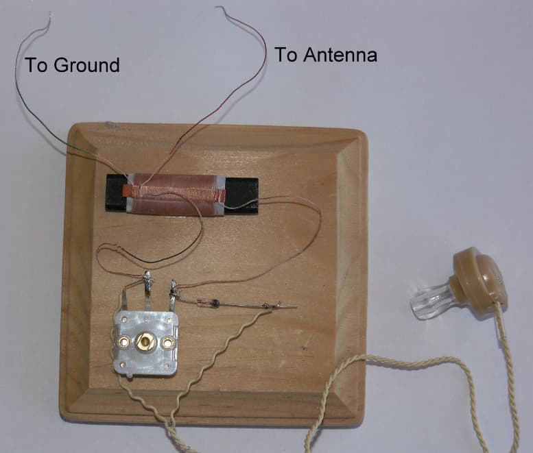
Figure 6: Basic Crystal Radio Circuit
Foundations of Basic Crystal Radio Circuits
The basic crystal radio circuit is defined by its simplicity. It consists of just a few key components: an inductor paired with a variable capacitor to create a tuned circuit, a diode for detecting signals, and a pair of headphones. While easy to build, this simple design has notable limitations. Without an antenna matching system, the circuit cannot effectively match the impedance of the antenna to the rest of the circuit, which results in a weaker signal. In addition, the direct connection of the detector and headphones to the tuned circuit places a significant load on it, further reducing both the selectivity and the strength of the received signal.
This design reflects the trade-offs made in early radio technology, where the focus was on keeping the construction simple and accessible, even if it meant sacrificing performance. While the circuit is easy for beginners to assemble, the lack of more sophisticated components limits its efficiency and signal quality.
Crystal Radio Circuits with Input Transformers
To improve how effectively a crystal radio receives signals from the antenna, more advanced designs often include an input transformer. This component is suitable for matching the high impedance of the receiver with the lower impedance of the antenna, making the signal transfer more efficient. However, while the input transformer enhances impedance matching, it doesn't completely optimize tuning across all frequencies.
This design choice reflects ongoing efforts to improve radio reception, illustrating the gradual enhancements made to push the limits of crystal radio technology. By incorporating the input transformer, designers sought to elevate performance, even as they navigated the inherent challenges and limitations of early radio systems.
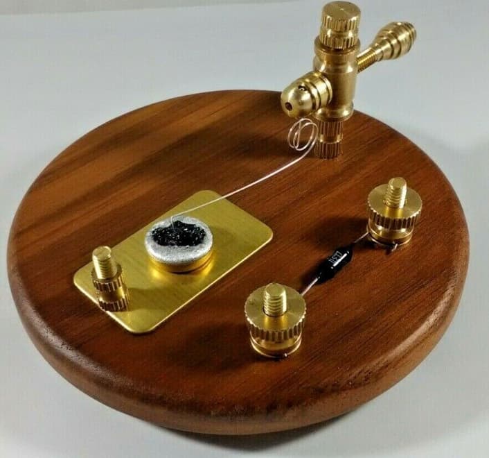
Figure 7: Carborundum Crystal Radio Circuit
Innovative Use of Carborundum in Crystal Radio Circuits
The use of carborundum detectors in crystal radio circuits represented a major technological leap, significantly improving reliability and reducing sensitivity to vibrations compared to earlier materials like galena. Unlike simpler detectors, carborundum detectors require a bias voltage, usually supplied by batteries, to operate effectively. While this adds to the cost, it also greatly enhances the circuit's performance.
The shift to carborundum in crystal radios reflects a progression toward more advanced, but also more expensive, technology. This evolution underscores the ongoing balance between cost, reliability, and stability in the design and development of radio receivers.
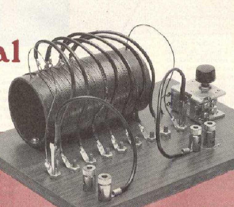
Figure 8: Tapped Coils
Signal Strength with Tapped Coils in Radio Design
Incorporating tapped coils into crystal radio designs greatly improved the circuit’s efficiency by reducing the load that detectors and headphones placed on the tuning coil. This modification increased the coil’s quality factor (Q) and improved impedance matching, leading to better overall performance. By adjusting the position of the tap on the coil, users could fine-tune the balance between volume output and circuit efficiency. This level of manual control allowed for precise adjustments, enabling operators to achieve clearer audio and stronger signals, significantly enhancing the listening experience.
Variable Coupling Techniques in Crystal Radio Circuits
Variable coupling in crystal radios represents a significant step forward in improving radio performance. This technique involves adjusting how the antenna and detector circuits interact, which allows for more precise tuning while also enhancing selectivity and sensitivity. By altering the coupling, users can directly influence the quality factor (Q) of the tuning circuit. This adjustment help for fine-tuning the radio's reception, helping to capture the desired signals more accurately and reduce interference.
The process of adjusting the coupling requires careful attention. Users need to incrementally change the coupling to find the optimal point where audio clarity is maximized without compromising signal strength. This delicate balance allows operators to achieve the best possible reception quality, making the listening experience more enjoyable.
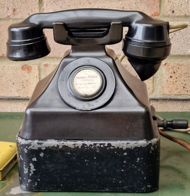
Figure 9: GECoPHONE No 1 Circuit
Classic GECoPHONE No 1 Circuit
The GECoPHONE No 1, introduced in 1923, stands as a key example of early radio innovation. This model featured a variometer, which allowed users to adjust the inductance of the inductor, enabling more precise tuning across different frequencies. This was a significant improvement over earlier crystal radios, which had more limited tuning capabilities.
With the variometer, users could explore a wider range of frequencies, making the radio more versatile and enhancing its overall performance. Fine-tuning the inductance was useful for optimizing signal reception and clarity, showcasing the ingenuity of early engineers in overcoming the limitations of basic radio designs.
Integrating a Single Transistor Amplifier/Detector
Modern crystal radios often incorporate a transistor amplifier, which significantly enhances audio output while keeping power consumption low. This update blends modern transistor technology with the classic crystal radio design, using a single transistor to function both as an amplifier and a detector. This approach boosts the radio's efficiency, delivering clearer and louder audio without requiring much energy.
The integration of the transistor preserves the simplicity and affordability of the original crystal radio, while greatly improving its performance. Users experience better audio quality, making the radio more practical and enjoyable to use in various settings. This enhancement makes crystal radios more versatile and effective, ensuring they remain relevant even with modern advancements.
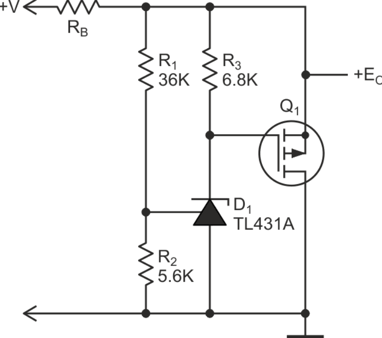
Figure 10: Crystal Radios with a TL431 Audio Amplifier
Crystal Radios with a TL431 Audio Amplifier
Adding a TL431 shunt regulator as an audio amplifier greatly enhances the performance of crystal radios. This amplifier allows the radio to power higher-impedance headphones and speakers, resulting in increased volume and a richer sound experience. The TL431 is known for its stability and low noise, making it ideal for providing clear and strong audio amplification.
This upgrade leads to a significant improvement in sound quality, delivering clearer and more powerful audio without distorting the original signal. As a result, users enjoy a more immersive and satisfying listening experience, with the amplifier boosting the signal while preserving the integrity of the sound. This enhancement makes crystal radios not only louder but also more precise in their audio output, elevating the overall user experience.
Building a Crystal Radio RF Amplifier for Enhanced Reception
For hobbyists aiming to enhance their crystal radio's performance, adding an RF (Radio Frequency) amplifier can be a game-changer. This upgrade increases the radio's sensitivity and selectivity, making it easier to pick up weaker signals and reduce background noise. A key feature of this setup is the use of regenerative feedback, which allows for precise control over the gain and audio quality.
With regenerative feedback, the RF amplifier selectively amplifies the signal, resulting in clearer and stronger audio reception. Operators can finely adjust these settings to optimize the radio's performance for specific listening conditions. This not only improves the radio's technical capabilities but also adds a layer of skill and satisfaction to the tuning process, making it a more engaging and rewarding experience.
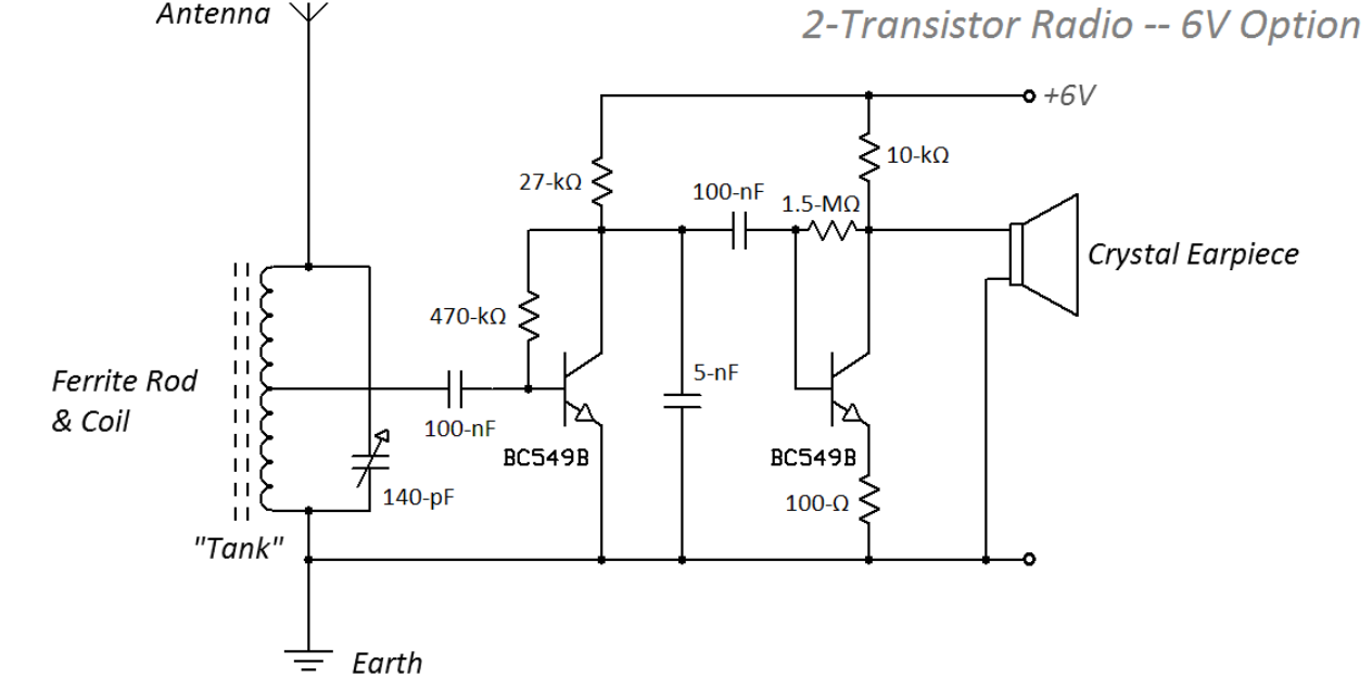
Figure 11: Two-Transistor Radio Design
Designing a Simple Two-Transistor Radio
The two-transistor radio design represents a step forward in simplicity and performance, offering a user-friendly approach that significantly improves both signal reception and audio output. This setup is particularly effective at picking up strong stations and can be built with easily accessible components. The design is straightforward, requiring minimal tuning, which makes it an excellent choice for both beginners and experienced hobbyists.
This two-transistor configuration enhances signal amplification and clarity, delivering a more reliable and enjoyable listening experience without the complexity of more advanced radios. By balancing ease of assembly with improved functionality, this design allows users to enjoy better audio quality with minimal hassle.
Conclusion
The enduring legacy of crystal radios is marked by their continuous evolution, driven by both technological advancements and the ingenuity of enthusiasts. As detailed in the article, each component of the crystal radio—from the antenna systems to the integration of modern semiconductor technologies—has been meticulously refined to improve functionality and performance. The evolution from simple galena detectors to sophisticated transistor amplifiers encapsulates a century of innovation that has dramatically enhanced the crystal radio's efficiency and user experience.
In addition, the progression towards incorporating complex components like the TL431 audio amplifier and tapped coils reflects a deeper understanding of electronic principles and user demands. These advancements not only enhance the acoustic output but also enrich the hobbyist's engagement with the medium. As crystal radios continue to fascinate and inspire, they remain a testament to the enduring appeal of hands-on experimentation and the perpetual quest for improving wireless audio reception within the realm of accessible technology. This exploration of crystal radio circuits not only highlights the technological milestones but also celebrates the spirit of continuous learning and adaptation that defines the amateur radio community.
Frequently Asked Questions [FAQ]
1. What is the crystal in a crystal radio?
The crystal in a crystal radio refers to a semiconductor material used as a detector or rectifier. Historically, the most common material used is galena (lead sulfide). It functions by allowing current to flow in one direction through the crystal to a thin wire touching it, known as a "cat's whisker," effectively demodulating the radio signal received by the antenna.
2. What are the different types of crystal radio?
Crystal radios vary mainly in their design and components but are fundamentally similar. Variations include:
Basic crystal radio: Consists of a coil, a diode (crystal detector), and an earpiece.
Tuned crystal radio: Includes a tunable capacitor for selecting different stations.
Amplified crystal radio: Incorporates a transistor or tube to amplify the signal for louder output or driving a speaker.
3. How to make crystal power radio?
To build a basic crystal radio, you need:
Antenna: A long wire to catch radio signals.
Tuning Coil: A coil of wire to select the radio frequency.
Diode (Crystal Detector): Typically, a germanium diode today.
Earphone: High-impedance earphones to hear the audio.
Ground Connection: A connection to the earth for stability and signal clarity. Assemble by connecting the antenna to one end of the coil. The other end connects to the diode, then to the earphone, and finally to the ground. Adjusting the coil or adding a variable capacitor allows tuning to different stations.
4. What are the 7 crystal systems?
The seven crystal systems are categories of crystals classified by their symmetry properties:
Cubic (or isometric): Characterized by three equal axes at right angles.
Tetragonal: Similar to cubic but with one axis longer or shorter than the other two.
Orthorhombic: Three unequal axes, all at right angles.
Hexagonal: Four axes where three are equal in length and lie in a single plane at 120° to each other, and the fourth axis is of a different length.
Trigonal (or rhombohedral): Axes and angles are identical but tilted away from being perpendicular.
Monoclinic: Two axes at right angles, the third axis is tilted.
Triclinic: All axes are of different lengths and none are at right angles.
5. What is an example of a crystal?
A common example of a crystal is quartz, which belongs to the hexagonal crystal system. Quartz crystals are widely used in watches and electronic equipment due to their ability to generate a stable, precise electronic frequency when subjected to mechanical stress (piezoelectric effect).
About us
ALLELCO LIMITED
Read more
Quick inquiry
Please send an inquiry, we will respond immediately.
Understanding USB3300-EZK Transceivers: Features, Applications, and Specifications
on September 3th
TP4056: Key Parameters, Functions, and Applications in Portable Devices
on September 3th
Popular Posts
-

What is GND in the circuit?
on January 1th 3083
-

RJ-45 Connector Guide: RJ-45 Connector Color Codes, Wiring Schemes, R-J45 Applications, RJ-45 Datasheets
on January 1th 2657
-

Understanding Power Supply Voltages in Electronics VCC, VDD, VEE, VSS, and GND
on November 14th 2177
-

Fiber Connector Types: SC Vs LC And LC Vs MTP
on January 1th 2174
-

Comparison Between DB9 and RS232
on January 1th 1796
-

What Is An LR44 Battery?
Electricity, that ubiquitous force, quietly permeates every aspect of our daily lives, from trivial gadgets to life-threatening medical equipment, it plays a silent role. However, truly grasping this energy, especially how to store and efficiently output it, is no easy task. It is against this background that this article will focus on a type of coin cell battery that may seem insignificant on the...on January 1th 1767
-

Understanding the Fundamentals:Inductance Resistance, andCapacitance
In the intricate dance of electrical engineering, a trio of fundamental elements takes center stage: inductance, resistance, and capacitance. Each bears unique traits that dictate the dynamic rhythms of electronic circuits. Here, we embark on a journey to decipher the complexities of these components, to uncover their distinct roles and practical uses within the vast electrical orchestra. Inductan...on January 1th 1724
-

CR2430 Battery Comprehensive Guide: Specifications, Applications and Comparison to CR2032 Batteries
What is CR2430 battery ?Benefits of CR2430 BatteriesNormCR2430 Battery ApplicationsCR2430 EquivalentCR2430 VS CR2032Battery CR2430 SizeWhat to look for when buying the CR2430 and equivalentsData Sheet PDFFrequently Asked Questions Batteries are the heart of small electronic devices. Among the many types available, coin cells play a crucial role, commonly found in calculators, remote controls, and ...on January 1th 1666
-

What Is RF and Why Do We Use It?
Radio Frequency (RF) technology is a key part of modern wireless communication, enabling data transmission over long distances without physical connections. This article delves into the basics of RF, explaining how electromagnetic radiation (EMR) makes RF communication possible. We will explore the principles of EMR, the creation and control of RF signals, and their wide-ranging uses. The article ...on January 1th 1662
-
Comprehensive guide to hFE in transistors
Transistors are crucial components in modern electronic devices, enabling signal amplification and control. This article delves into the knowledge surrounding hFE, including how to select a transistor's hFE value, how to find hFE, and the gain of different types of transistors. Through our exploration of hFE, we gain a deeper understanding of how transistors work and their role in electronic circu...on November 14th 1612


