Decoding the Mechanics of Switch Poles and Throws
In the complex realm of electronics, switches play an important role in managing circuit functions across diverse devices, extending from simple lighting controls to advanced electronic systems. This article examines the dynamic elements and various types of switches, exploring their operational mechanisms and required roles. It categorizes switches into single and double pole configurations, along with single or double throws, shedding light on the key aspects of switch design and application. Understanding the unique features of each switch type—from the basic Single Pole Single Throw (SPST) to the adaptable Double Pole Double Throw (DPDT)—enables designers and engineers to enhance circuit functionality and efficiency. The discussion covers important factors in switch selection, such as size, default state, actuation methods, and environmental considerations, which are deciding for incorporating these components into high-performing electronic systems. This comprehensive overview aids in selecting the right switch to meet specific design requirements.
Catalog
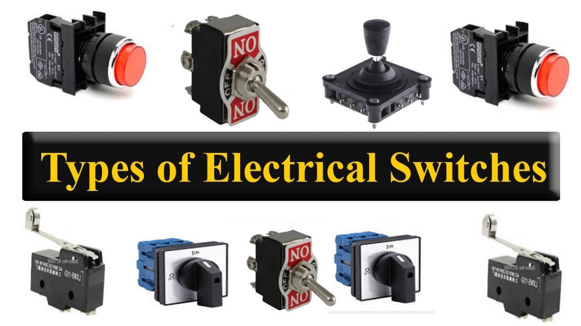
Figure 1: Electrical Switch Varieties
Various Types of Electrical Switches
Switches play an insistent role in electronics, controlling and managing the flow of electrical current in circuits. Their function extends beyond just lighting control. Electromechanical switches are particularly important for making or breaking electrical circuits and are necessary for the operation of many devices.
Single Pole Single Throw (SPST)
The SPST switch is the simplest type. It controls a single circuit with an on-off position. It's like a basic light switch, turning the current flow on or off.
Single Pole Double Throw (SPDT)
The SPDT switch manages one input circuit but can toggle between two separate output circuits. Imagine a switch that can direct the current to either one of two lights.
Double Pole Single Throw (DPST)
The DPST switch simultaneously controls two independent circuits with a single on-off switch. It's like having two SPST switches operated by a single lever.
Double Pole Double Throw (DPDT)
The DPDT switch offers control over two circuits, allowing each to be connected to one of two outputs. Think of it as a pair of SPDT switches combined, enabling more complex control.
Each type of switch has a unique structure and functionality, affecting how they integrate into devices. Manual switches operate on the same basic principles as relays, which are switches activated electromechanically by an electrical signal.
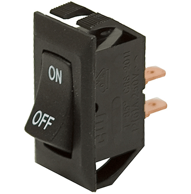
Figure 2: SPST Switch
Understanding the Basics of SPST Switches
The Single Pole Single Throw (SPST) switch exemplifies simplicity in switch design, operating on a straightforward "ON/OFF" mechanism. This switch features two terminals. When toggled to "ON," these terminals connect, completing the circuit and allowing electrical current to flow. This action activates the device connected to the switch, such as a light. Flipping the switch to "OFF" disconnects the terminals, interrupting the current and deactivating the device.
The SPST switch's design is minimalistic, involving a simple toggle mechanism that either establishes or severs the electrical pathway. This simplicity facilitates ease of use and enhances reliability, as fewer components could fail. These switches are widely used in applications requiring straightforward control of a single circuit, demonstrating effectiveness without redundant complexity.
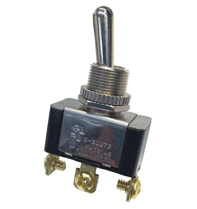
Figure 3: SPDT Switch
Explaining the SPDT Switch: What You Need to Know?
The Single Pole Double Throw (SPDT) switch stands out for its versatility, featuring three terminals. This setup allows the switch to connect one power source to either of two output terminals. Users can choose between the "ON-1" or "ON-2" positions, directing the current to different terminals and completing one of two separate circuits. This dual-pathway feature efficiently manages multiple operations through a single switch.
Many SPDT switches also have a central "OFF" position, which cuts off power from both output terminals. This feature enhances safety and prevents accidental activations. This is particularly useful in applications requiring precise control over circuit connections, such as in dual-function devices or complex machinery. The SPDT switch thus provides flexible circuit management along with increased operational security.
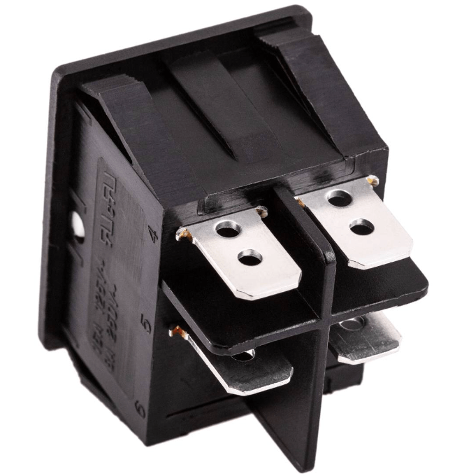
Figure 4: DPST Switch
How DPST Switches Operate?
The Double Pole Single Throw (DPST) switch has four terminals, allowing it to connect two separate circuits at the same time but independently. It works like two SPST switches in one, enabling parallel management of two circuits while keeping them electrically isolated. This isolation is required to prevent cross-connections, especially in high-voltage or multifunctional devices.
The DPST switch is perfect for systems where dual circuit control is needed in a single action, boosting both safety and efficiency. It is commonly used in complex machinery and electrical systems, where isolating circuits prevents interference between components, ensuring both operational integrity and safety.
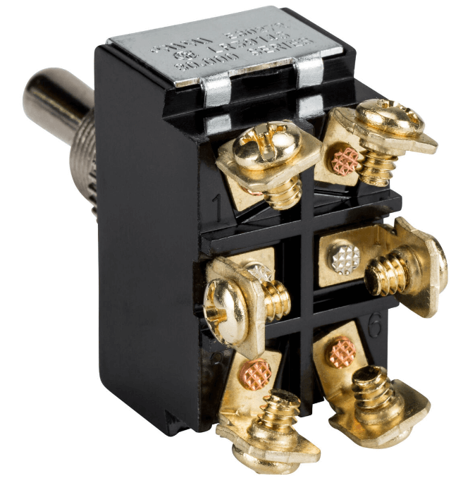
Figure 5: DPDT Switch
DPDT Switches: Structure, Function, and Uses
The Double Pole Double Throw (DPDT) switch has six terminals, allowing each of its two poles to connect independently to one of two outputs. This setup enables the simultaneous operation of two separate circuits, making the DPDT switch highly versatile for complex circuit designs.
To integrate a DPDT switch accurately into electronic systems, consulting datasheets is a must. This ensures proper understanding and application, leading to optimal performance and compatibility with other circuit components. The DPDT switch is especially useful for applications needing reversible motor controls or independent operation of two devices, offering precise control in sophisticated electronic
Criteria for Selecting the Ideal Electrical Switch
When selecting a switch, it's settling to evaluate several key features beyond just poles and throws.
Features to Consider for Switch Selection:
|
Features to Consider for Switch
Selection |
|
|
Size and Form Factor |
The physical dimensions and shape of the
switch determine its fit in space-limited applications. A compact design is useful
for small devices, while larger switches may be better suited for industrial
use |
|
Default State |
This indicates whether the switch is
normally in an "ON" or "OFF" position when not in use.
This default position affects how circuits are managed and controlled, making
it an analytic consideration. |
|
Positions |
The number of stable positions the switch
can occupy influences its functionality in circuit design. Such as a switch
with multiple positions can control various functions within a device. |
|
Mounting Options |
The method of securing the switch to a
panel or device impacts both installation and maintenance. Options include
panel mount, surface mount, or through-hole mount, each offering different
benefits and challenges. |
|
Actuation Method |
The way the switch is operated—whether by
toggle, push-button, rocker, or another method—affects user interaction and
overall experience. Each method offers unique advantages in terms of ease of
use and functionality. |
|
Current and Voltage Ratings |
These ratings specify the maximum
electrical load the switch can handle safely. High ratings are required for
industrial applications, while lower ratings may suffice for consumer
electronics. |
|
Environmental Factors |
The switch's operating conditions,
including temperature, humidity, and exposure to corrosive elements, dictate
its material and design specifications. Switches in harsh environments need
to be particularly robust and durable. |
Mechanical Switches: Varieties and Practical Applications
Mechanical switches are basic components in various electronic and mechanical systems, serving to connect or disconnect electrical circuits under different conditions. These switches are selected based on their functionality, environmental compatibility, and the specific requirements of the application. Below is an expanded discussion of the common types of mechanical switches:
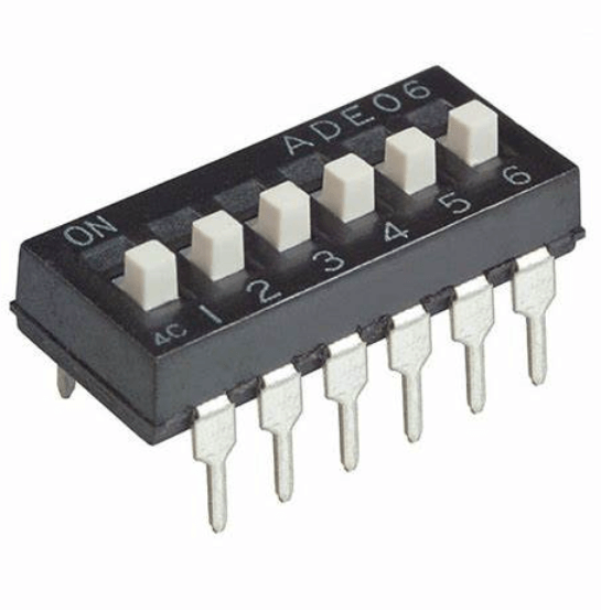
Figure 6: Dual In-line Package (DIP)
Many electronic systems require Dual In-line Package (DIP) switches, especially when it comes to hardware configurations. Consisting of a series of manual electric switches housed in a compact enclosure, DIP switches are known for their simplicity and effectiveness. They are typically mounted directly onto circuit boards and are characterized by their small, rectangular shape.
DIP switches are composed of multiple toggle switches that can be set to on or off positions, allowing for binary configuration options. Each switch on a DIP unit can represent a single bit of binary code, with the combination of all switches representing a binary number. The body of a DIP switch is typically made from durable plastic, with the switches themselves being metallic. These components are designed to ensure reliable performance and a long operational life.
DIP switches come in various types including Slide-Type, which uses a small slider to control the circuit; Rocker-Type, which employs a seesaw mechanism; Rotary-Type, featuring a rotary dial for more setting options in a limited space; and Piano-Type, similar to piano keys, where buttons are pressed to adjust settings. These switches are used primarily to set operating parameters, configure devices, and address hardware before activation, with applications ranging from adjusting computer hardware settings to setting network device addresses and enabling electronic device features. DIP switches are valued for their simplicity, reliability, flexibility, and cost-effectiveness, allowing straightforward hardware adjustments without software and offering a customizable experience at minimal cost. However, they have limitations including the necessity for physical access, a limited number of settings, and potential size constraints in modern miniaturized applications.
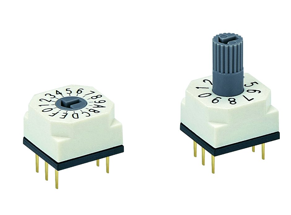
Figure 7: Rotary DIP Switches
Rotary DIP (Dual In-line Package) switches are a specialized type of switch that provides multiple configuration settings through a rotating selector. These switches are particularly valued in electronic applications where precise setting adjustments are needed within a compact space. The design of rotary DIP switches allows them to offer a high degree of functionality and flexibility in a small footprint, making them ideal for various industrial, commercial, and consumer electronics contexts.
A rotary DIP switch comprises key components such as a rotating selector for choosing settings, multiple electrical contacts arranged circularly to close different circuits based on the selector's position, and a housing that contains this internals in a small, rectangular package suitable for standard DIP sockets. These switches find use in various applications requiring multiple settings in constrained spaces, like circuit configuration on PCBs, device configuration in electronics like garage door openers and security systems, and industrial controls for setting operation modes. The advantages of rotary DIP switches include their compact design, precise control, versatility for binary or complex mode selections, and ease of use, allowing settings adjustments by simply turning a knob. When choosing a rotary DIP switch, considerations such as the number of positions, current and voltage ratings, environmental resistance, and mounting style are insistent to ensure the switch meets the application's demands and withstands any harsh conditions. This blend of functionality and design efficiency makes rotary DIP switches a favored option for many manual configuration and adjustment needs in electronic devices.
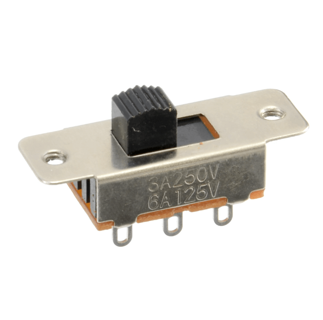
Figure 8: Slide Switches
Slide switches are a type of mechanical switch that allows users to control an electrical circuit by sliding a small lever or handle back and forth. This sliding action either makes or breaks the circuit's electrical connection, typically resulting in an on or off state. Due to their straightforward design and reliable operation, slide switches are widely used in a variety of applications, particularly in consumer electronics.
A typical slide switch consists of key components including an actuator connected to a slider that moves linearly within the switch body to open or close the electrical contacts, and a housing that protects these internals from environmental factors. Slide switches are commonly used in various devices, such as lighting controls to operate lamps, consumer electronics like radios and cameras for power management, and industrial machinery for controlling power circuits and modes. The advantages of slide switches include their durability, capable of enduring numerous cycles without failure; simplicity, with an intuitive sliding mechanism that is easy to operate; and a compact design that fits well in small or portable devices. When selecting a slide switch, it is important to consider the current and voltage ratings to handle the application's electrical load, the physical size and footprint for space constraints, the materials used for durability and environmental suitability, and the mechanical resistance that can affect the user experience. Slide switches offer a reliable, straightforward way to manage electrical circuits in a wide array of applications, from simple household uses to complex industrial controls.
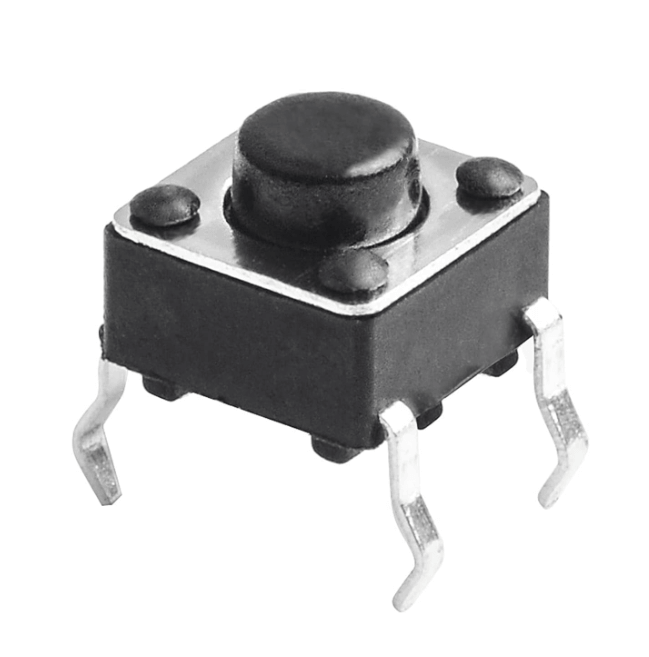
Figure 9: Tactile Switches
Tactile switches are a popular choice in user interface design for their distinct physical feedback, often characterized by a noticeable "click" sensation when pressed. This tactile response not only confirms the activation of the switch but also enhances the user experience by providing immediate physical feedback, which is especially valuable in environments where visual or auditory confirmation might be less effective.
A tactile switch is composed of main components like a button or actuator that the user presses, a dome or plunger that provides springy feedback when pressed, conductive contacts that close the electrical circuit, and a housing usually made from durable plastic or metal to encase these parts. These switches are widely used in various applications such as computer and calculator keyboards for their quick response, consumer electronics like remote controls and mobile phones, and industrial controls where reliable feedback is insistent. The benefits of tactile switches include providing clear feedback to prevent operational errors, their compact size which fits well in space-constrained designs, and their versatility across numerous devices from simple gadgets to complex machinery. When choosing a tactile switch, considerations such as the actuation force required, the durability to withstand expected usage, and appropriate current and voltage ratings for the application are critical to ensure both functionality and user comfort.
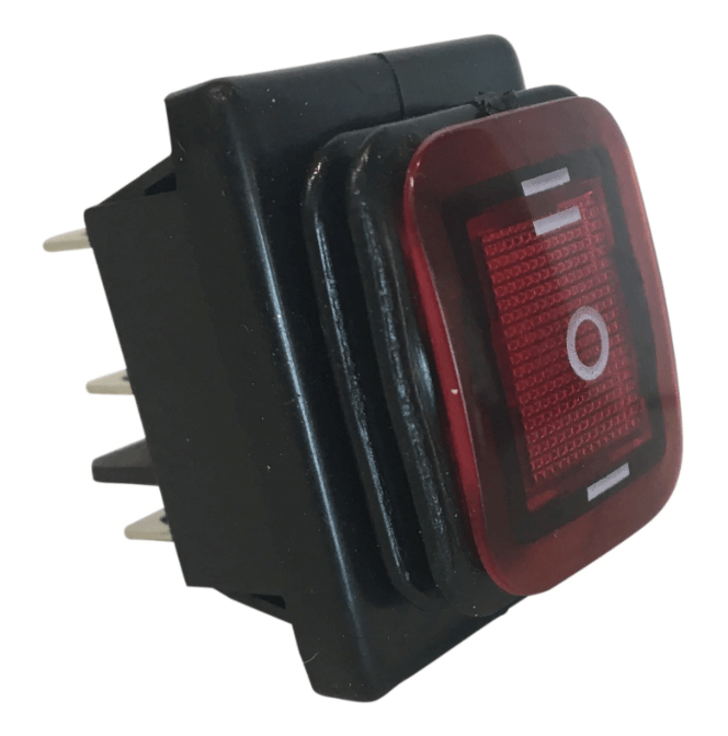
Figure 10: Rocker Switches
Rocker switches are another form of mechanical switch, named for their rocking mechanism that toggles between positions. They are commonly used for power toggling and feature an easy-to-use interface that rocks from one side to the other to close or open the circuit.
A rocker switch consists of an actuator that rocks on a central fulcrum to control the circuit, contacts that establish or interrupt the electrical connection, and housing that shields internal components from environmental damage. These switches are prevalent in both consumer and industrial settings, such as in-home appliances like coffee makers and blenders for straightforward on/off controls, automotive panels for operating lights and other features, and power strips and surge protectors. Rocker switches offer several advantages including ease of use due to their large surface, a visual status indication from the switch's position, and design flexibility to meet diverse aesthetic and functional needs. When selecting a rocker switch, important considerations include matching the electrical specifications with the application's requirements, choosing an appropriate mounting method and orientation for optimal usability and installation, and selecting durable materials suitable for the environmental conditions where the switch will be used.
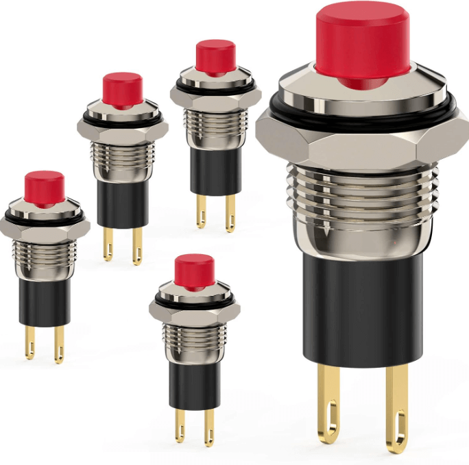
Figure 11: Push Button Switches
Push button switches are an ultimate component in both industrial and consumer electronics, offering a simple and effective means to momentarily activate or deactivate devices. The design of these switches allows for quick and responsive control, making them highly suitable for applications that require immediate and straightforward interaction.
A typical push button switch comprises several key components such as an actuator or button that users press to operate, internal conductive contacts that make or break an electrical circuit upon pressing and releasing, a spring mechanism for returning the button to its original position, and a housing that encases these components, usually made of plastic or metal for durability and protection against environmental factors. Push button switches are widely used across various applications, including in industrial machinery for starting and stopping processes, in medical devices for controlling operations, in consumer electronics like keyboards and appliances, and public facilities for emergency stops and pedestrian signals. These switches offer immediate activation for serious timing applications, user-friendliness with their simple design, durability for enduring numerous actions, and versatility with various sizes, colors, and configurations. When choosing a push button switch, important considerations include the choice between momentary and maintained contact, suitability for environmental conditions, compliance with electrical requirements, and appropriate mounting options to fit specific device designs.
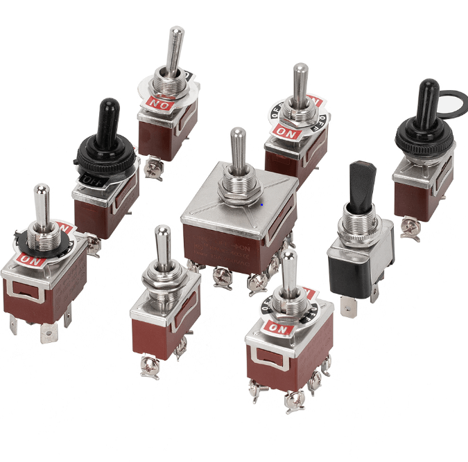
Figure 12: Toggle Switches
Toggle switches are widely recognized for their robust construction and straightforward operation, making them highly suitable for applications that require a durable switching solution with clear visual feedback regarding the switch's status. These switches function through a simple mechanical lever or baton that users flip to one side or the other to open or close an electrical circuit.
Toggle switches consist of key components such as a lever or baton that users manipulate, snapping into different positions, metal contacts that make or break electrical connections based on the lever's position, and housing typically made of metal or high-strength plastic to encase and protect these internal elements. They are widely used in various settings due to their reliability and ease of use, including in industrial equipment for power and mode operations, automotive systems for controlling lights and wipers, aviation and marine control panels, and audio-visual equipment for power and operational controls. Advantages of toggle switches include their durability, with many designed to withstand thousands of use cycles, clear position indication through the lever's physical position, intuitive operation, and versatility with various sizes, configurations, and current ratings available to meet different needs. When choosing a toggle switch, considerations include matching the electrical specifications with the application’s needs, ensuring environmental suitability for exposure to harsh conditions, appropriate mounting for the device or enclosure, and possibly incorporating safety features like locking mechanisms or waterproof covers to enhance operation safety and durability.
Characteristics of High-Performance Switches
Considering the basic characteristics of a switch, such as poles and throws, is necessary to define the functionality of the switch and determine its suitability for various electronic systems. Key distinctions include:
Momentary Switches: These switches remain active only while being pressed. They are suitable for applications requiring a temporary circuit connection, such as keyboards or doorbells.
Latched Switches: These switches stay in their last state until activated again. They are ideal for applications needing a stable switch position, like light switches or power controls.
Grasping these characteristics ensures the effective integration of switches into electronic designs. It enhances safety by matching the correct switch type to the specific needs of each application.
Conclusion
Throughout this discussion, it becomes evident that the selection and application of electrical switches are not merely about toggling between on and off states but about enhancing the operational efficiency and safety of electronic devices. The detailed examination of various switch types—from SPST to DPDT—reveals the nuanced applications and the analytic engineering behind each configuration. In addition, by addressing the broader considerations such as environmental factors, mounting options, and current and voltage ratings, the article underscores the complexity involved in choosing the right switch for specific applications.
This comprehensive analysis not only aids in the practical understanding of switch functionality but also serves as a foundational guide for engineers and designers to make informed decisions, ensuring the reliability and efficiency of electronic circuits in a myriad of applications. By integrating these insights, professionals in the electronics industry can advance their designs, thereby pushing the boundaries of what is possible in the ever-evolving landscape of electronic technology.
Frequently Asked Questions [FAQ]
1. How does a pole switch work?
A pole switch operates by making or breaking a connection in an electrical circuit. The term "pole" refers to the number of separate circuits that the switch can control. When you toggle a switch, it connects or disconnects these circuits, allowing or stopping the flow of electricity. For example, in a simple light switch, flipping the switch completes the circuit to turn on the light and breaks the circuit to turn it off.
2. What are the poles and throws of a relay?
In a relay, "poles" refer to the number of separate circuits the relay can control, similar to switches. "Throws" indicate the number of positions each circuit can connect to. For example, a single-pole single-throw (SPST) relay can control one circuit and connect it to one other position. A double-pole double-throw (DPDT) relay can control two circuits, each connecting between two positions, allowing more complex control in electrical systems.
3. What does it mean when the poles switch?
When the poles switch in an electrical device like a relay or switch, it refers to changing the connections within the device. This change redirects the flow of electricity from one circuit path to another. It’s the action of moving from one connection point (or throw) to another across the available poles, thus altering the operational path of the circuit.
4. What are the poles of a circuit?
The poles of a circuit represent the points where the circuit can connect to or disconnect from other parts of the system. These are serious, for controlling how electricity is distributed and controlled within any electrical system. In switches and relays, poles are the points of contact that determine the flow of electrical current through various paths.
5. What are the basics of switches?
The basics of switches involve controlling the flow of electricity. A switch typically has two main states: 'on', where the circuit is complete and electricity flows, and 'off', where the circuit is open and electricity does not flow. Switches come in various types and complexities, from simple on-off versions to more complex multi-pole, multi-throw configurations, each designed to control different aspects of electrical circuits in specific ways.
About us
ALLELCO LIMITED
Read more
Quick inquiry
Please send an inquiry, we will respond immediately.
Pinout
on July 1th

Understanding Power Supply Voltages in Electronics VCC, VDD, VEE, VSS, and GND
on June 29th
Popular Posts
-

What is GND in the circuit?
on January 1th 2946
-

RJ-45 Connector Guide: RJ-45 Connector Color Codes, Wiring Schemes, R-J45 Applications, RJ-45 Datasheets
on January 1th 2502
-

Fiber Connector Types: SC Vs LC And LC Vs MTP
on January 1th 2091
-
Understanding Power Supply Voltages in Electronics VCC, VDD, VEE, VSS, and GND
on November 9th 1898
-

Comparison Between DB9 and RS232
on January 1th 1765
-

What Is An LR44 Battery?
Electricity, that ubiquitous force, quietly permeates every aspect of our daily lives, from trivial gadgets to life-threatening medical equipment, it plays a silent role. However, truly grasping this energy, especially how to store and efficiently output it, is no easy task. It is against this background that this article will focus on a type of coin cell battery that may seem insignificant on the...on January 1th 1714
-

Understanding the Fundamentals:Inductance Resistance, andCapacitance
In the intricate dance of electrical engineering, a trio of fundamental elements takes center stage: inductance, resistance, and capacitance. Each bears unique traits that dictate the dynamic rhythms of electronic circuits. Here, we embark on a journey to decipher the complexities of these components, to uncover their distinct roles and practical uses within the vast electrical orchestra. Inductan...on January 1th 1662
-

CR2430 Battery Comprehensive Guide: Specifications, Applications and Comparison to CR2032 Batteries
What is CR2430 battery ?Benefits of CR2430 BatteriesNormCR2430 Battery ApplicationsCR2430 EquivalentCR2430 VS CR2032Battery CR2430 SizeWhat to look for when buying the CR2430 and equivalentsData Sheet PDFFrequently Asked Questions Batteries are the heart of small electronic devices. Among the many types available, coin cells play a crucial role, commonly found in calculators, remote controls, and ...on January 1th 1567
-

What Is RF and Why Do We Use It?
Radio Frequency (RF) technology is a key part of modern wireless communication, enabling data transmission over long distances without physical connections. This article delves into the basics of RF, explaining how electromagnetic radiation (EMR) makes RF communication possible. We will explore the principles of EMR, the creation and control of RF signals, and their wide-ranging uses. The article ...on January 1th 1550
-

CR2450 vs CR2032: Can The Battery Be Used Instead?
Lithium manganese batteries do have some similarities with other lithium batteries. High energy density and long service life are the characteristics they have in common. This kind of battery has won the trust and favor of many consumers because of its unique safety. Expensive tech gadgets? Small appliances in our homes? Look around and you'll see them everywhere. Among these many lithium-manganes...on January 1th 1519
HOT Part Number
-

SCE110AB160
SanRex Corporation
THYRISTOR MODULE 1600V 110A
TLVH431QDBZR
Texas Instruments
IC VREF SHUNT ADJ 1.5% SOT23-3
SMCJ22CAQ-13-F
Diodes Incorporated
TVS DIODE 22VWM 35.5VC SMC
MB4204PF-G-JN-ER-2KE1
Infineon Technologies
IC REG DC/DC CONV 14SOP
EMI8141MUTAG
onsemi
CMC 100MA 2LN SMD ESD
74F02PC
onsemi
IC GATE NOR 4CH 2-INP 14DIP
LMC6084AIM
Texas Instruments
IC CMOS 4 CIRCUIT 14SOIC
MAX6315US31D1+T
Analog Devices Inc./Maxim Integrated
IC SUPERVISOR 1 CHANNEL SOT143-4
S-1172B25-E6T1G
ABLIC Inc.
IC REG LINEAR 2.5V 1A 6HSOP
STM8S207S6T3CTR
STMicroelectronics
IC MCU 8BIT 32KB FLASH 44LQFP
4608X-102-223LF
Bourns Inc.
RES ARRAY 4 RES 22K OHM 8SIP
MC33879EKR2
NXP USA Inc.
IC PWR SWITCH N-CHAN 1:4 32SOIC
AOSS62934
Alpha & Omega Semiconductor Inc.
MOSFET N-CH 100V 2A SOT23-3
EP20K100EFC324-1X
Intel
IC FPGA 246 I/O 324FBGA
MAX1681ESA+
Analog Devices Inc./Maxim Integrated
IC REG CHARGE PUMP INV 8SOIC
AP5724WG-7
Diodes Incorporated
IC LED DRV RGLTR PWM 750MA SOT26
LTC4261CGN-2#TRPBF
Analog Devices Inc.
IC HOT SWAP CTRLR -48V 28SSOP
BA178M05T
Rohm Semiconductor
IC REG LINEAR 5V 500MA TO220FP -

MAX4522CEE+
Analog Devices Inc./Maxim Integrated
IC SW SPST-NOX4 100OHM 16QSOP
DS1002
Box Partners
3.6 MIL MOISTURE BARRIER BAG, 6"
XC5VLX50-1FFG1153C
AMD
IC FPGA 560 I/O 1153FCBGA
1N3743R
Microchip Technology
DIODE GP REV 1.2KV 275A DO205AB
ADS5522IPAPG4
Texas Instruments
IC ADC 12BIT 80MSPS 64-HTQFP
FARM1E11
Vicor Corporation
FARM1 "E" 500W SP SLOT
EPM7512AETC144-10N
Intel
IC CPLD 512MC 10NS 144TQFP
SUCS61205C
Cosel USA, Inc.
DC DC CONVERTER 5V
TPS73218DCQRG4
Texas Instruments
IC REG LIN 1.8V 250MA SOT223-6
LFXP6E-3FN256I
Lattice Semiconductor Corporation
IC FPGA 188 I/O 256FBGA
CC0603JRX7R0BB103
YAGEO
CAP CER 10000PF 100V X7R 0603
RJP4009ANS-01#Q5
Renesas Electronics America Inc
IGBT NCH 400V 8VSON
EL5163IW-T7A
Renesas Electronics America Inc
IC OPAMP CFA 1 CIRCUIT SOT23-5
HUF75639G3
Fairchild Semiconductor
N-CHANNEL ULTRAFET POWER MOSFET
MMBZ5252B
onsemi
ZENER DIODE, 24V, 5%, 0.35W, UNI
GSOT24C-E3-08
Vishay General Semiconductor - Diodes Division
TVS DIODE 24VWM 47VC SOT23-3
QMK212SD681KD-T
Taiyo Yuden
CAP CER 680PF 250V 0805
ISL6439IB
Renesas Electronics America Inc
IC REG CTRLR BUCK 14SOIC -

MAX491ECPD+
Analog Devices Inc./Maxim Integrated
IC TRANSCEIVER FULL 1/1 14DIP
AD8018ARU-REEL7
Analog Devices Inc.
IC XDSL LINE DVR R-R 14-TSSOP
MCF51MM128CLK
NXP USA Inc.
IC MCU 32BIT 128KB FLASH 80FQFP
P6SMB43CA
Eaton - Electronics Division
TVS DIODE 36.8VWM 59.3VC SMB
FQPF10N20
onsemi
MOSFET N-CH 200V 6.8A TO220F
CC0402JRX7R9BB151
YAGEO
CAP CER 150PF 50V X7R 0402
74VHCT573ASJ
Fairchild Semiconductor
BUS DRIVER
SC339SKTRT
Semtech Corporation
IC LNR REG CTRLR 1OUT SOT23-6
T491D106K035AS
KEMET
CAP TANT 10UF 10% 35V 2917
V300B24H250B
Vicor Corporation
DC DC CONVERTER 24V 250W
UVZ1V472MHD
Nichicon
CAP ALUM 4700UF 20% 35V RADIAL
HK06036N2S-T
Taiyo Yuden
FIXED IND 6.2NH 250MA 380MOHM SM
OPA569AIDWP
Texas Instruments
IC OPAMP GP 1 CIRCUIT 20HSOIC
MAX398ESE+T
Analog Devices Inc./Maxim Integrated
IC MUX 8:1 100OHM 16SOIC
1812AA101KAT1A
KYOCERA AVX
CAP CER 100PF 1KV C0G/NP0 1812
XG4C-6431
Omron Electronics Inc-EMC Div
CONN HEADER VERT 64POS 2.54MM
ISL23418UFUZ
Renesas Electronics America Inc
IC DGTL POT 50KOHM 128TAP 10MSOP
1-1600961-8
TE Connectivity AMP Connectors
CONTACT BLADE SCKT PWR 12-16AWG