Pinout
In the complicated world of electronics, understanding pinouts is very useful for anyone working with electronic parts or circuit boards. A pinout is a diagram or list that shows the electrical connections within an electronic part, displaying how the pins are arranged and what each pin does. Whether you're a technician, engineer, or hobbyist, learning the basics of pinouts helps make sure connections are correct and safe. This article will explain the basics of pinouts, their different parts, how to read them, and give practical examples, providing a complete guide to understanding this important part of electronics.
Catalog
What Is a Pinout?

Figure 1: Pinout Diagram Showing the Electrical Connections (pins) of an Electronic Part or Circuit Board
This diagram or list that shows the electrical connections (pins) within an electronic part or circuit board. It displays the arrangement of pins and their functions, serving as a guide for connecting and using the device. Pinouts help technicians, engineers, and hobbyists correctly identify and connect the various pins or terminals.
Pinouts make sure each pin is connected to the right terminal, preventing problems or damage. For example, a computer power supply pinout shows which pins are for ground and which are for +5V power, ensuring proper connections for the power button and ground wires.
Typically, a pinout diagram is laid out in a parallel format, with each row representing the same type of connection across different columns. To read a pinout, start from the leftmost column and move row by row to the right. This method helps accurately track each connection, avoiding mistakes that could lead to wrong wiring or device damage.
Understanding a pinout involves knowing what each column and row represents, such as input, output, voltage reference, analog, digital signals, and power connections. Each row provides specific details like voltage, current, and capacitance to ensure compatibility and proper function. For example, an input pinout details the input voltage range, current, and capacitance needed by the component, while an output pinout describes the output voltage, current, and capacitance provided by the component.
A standard USB pinout, for instance, includes two power lines and two signal lines, specifying which pins correspond to +5V, ground (GND), and data lines (D+ and D-). Similarly, the RS-232 pinout for serial communication between computers and peripheral devices defines the function of each of the 9 pins, such as data transmission, handshake signals, and ground, aiding in setup and troubleshooting.
Parts of a Pinout
Understanding the parts of a pinout is very helpful for using electronic parts correctly. Each part of a pinout helps to identify and connect the pins in an electronic circuit properly.
Pin Number
The pin number is key for identifying each pin on a component. Each pin is given a unique number, usually shown in order. This numbering system makes it easy for users to find and refer to specific pins when looking at a pinout diagram or connecting components.
Pin Name
The pin name tells what the pin does. This name gives immediate information about the pin's role in the circuit. For example, common pin names might include "GND" for ground, "VCC" for power supply voltage, "RX" for receiving data in communication interfaces, and "TX" for sending data.
Pin Description
The pin description provides more details about the pin, such as its voltage, current, or signal type. This information helps in understanding how the pin works and making sure it is used within its limits. For instance, a pin description might state that a certain pin can handle up to 5 volts and 1 amp of current, or that it is an analog input capable of reading different voltage levels.
Pin Connection
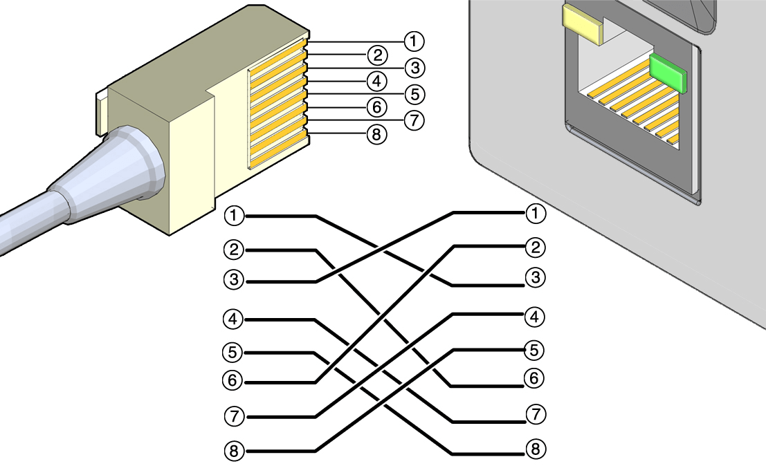
Figure 2: Pin Connection Diagram for an Ethernet Cable and Port
The pin connection section shows how the pin is connected to other parts or devices. This includes stating whether the pin is an input or an output and describing its interaction with the rest of the circuit. For example, an input pin on a microcontroller might be connected to a sensor, while an output pin might control an LED or relay.
How to Read a Pinout?
• Find the Pinout Diagram: Locate the pinout diagram or table for the specific component you are working with. This information is usually found in the datasheet or technical manual from the manufacturer.
• Study the Pin Layout: Familiarize yourself with the overall layout of the pinout, including the pin numbers and their names. Pinouts are typically displayed in a grid format where each pin is marked by a unique number or letter.
• Understand the Pin Functions: Each pin has a specific role, such as input, output, ground, or power. Carefully read the pin descriptions to understand each pin's function.
• Examine the Pin Connections: Check how the component connects to other components or devices to ensure each pin is connected correctly, preventing malfunction or damage.
• Check the Datasheet: If you encounter any unfamiliar terms or symbols while studying the pinout, refer to the datasheet for clarification. Datasheets provide detailed explanations of each pin, including electrical characteristics, timing diagrams, and usage examples.
Tips for Reading Pinouts
Understanding pinouts allows anyone working with electronics to properly connect different components. Here are some practical tips to help you read and understand pinouts better:
• Pay Attention to Pin Types: Pins can have different functions such as power, ground, input, output, or communication. Knowing each pin's role helps prevent incorrect connections.
• Use Color Codes: Some pinouts use standard color codes to denote different functions, making it easier to identify pin functions.
• Double-Check Pin Numbers: Always verify pin numbers to ensure correct connections, as mistakes can damage parts or cause malfunctions.
• Consult Online Resources: Online communities and resources dedicated to electronics can provide additional guidance and answer specific questions about pinouts.
Practical Examples of Pinouts
Raspberry Pi GPIO Pinout
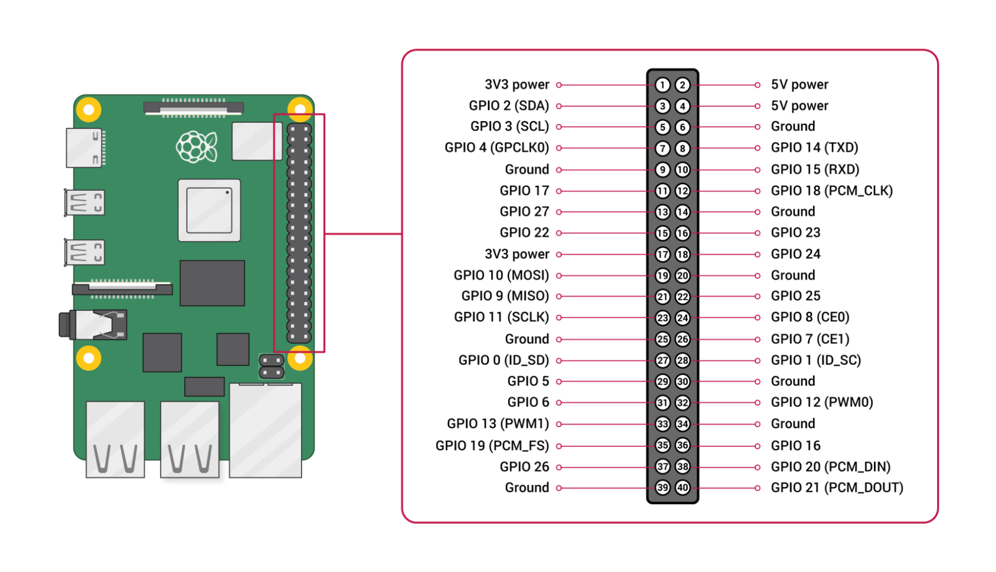
Figure 3: Raspberry Pi GPIO Pinout
The Raspberry Pi is a very useful small computer that can be used for many different projects, like making your home smarter or building robots. Its GPIO (General Purpose Input/Output) pin layout gives detailed information about what each pin does.
3.3V Power: Provides power to parts that need 3.3V.
5V Power: Provides power to parts that need 5V.
Ground (GND): Gives a path for electricity to return, which helps keep the circuit working well.
GPIO pins are used for digital input and output tasks, allowing the Raspberry Pi to connect and work with sensors, motors, and other devices.
I2C Communication: Uses SDA (data) and SCL (clock) pins to connect several devices with just two wires, making it perfect for sensors and other add-ons.
SPI Communication: Uses MOSI (Master Out Slave In), MISO (Master In Slave Out), and SCK (Serial Clock) pins for fast connections to devices like SD cards and screens.
UART Communication: Uses TX (transmit) and RX (receive) pins for serial communication with things like GPS and Bluetooth modules.
PWM Outputs: PWM (Pulse Width Modulation) outputs from certain GPIO pins create signals that mimic analog signals, letting you control things like servo motors, other motors, and LED brightness.
USB Type-C Pinout
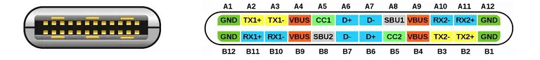
Figure 4: USB Type-C Pinout
USB Type-C is a flexible connector used in smartphones, laptops, and tablets. It can handle power delivery, data transfer, and video output all through one cable. The pin layout is complex, with each pin having a specific role.
VBUS pin supplies power needed to charge devices or power accessories.
GND pin provides a ground connection, which is needed to complete electrical circuits and ensure safety.
CC (Configuration Channel) pins manage connection settings and power delivery, deciding how much power is sent and in which direction, based on what connected devices need.
D+ and D- pins are USB 2.0 data lines responsible for basic data transfer, making sure the connector works with older USB versions.
TX/RX pairs (USB 3.1 data lines) are used for higher-speed data transfer, greatly increasing how fast data can be sent and received.
SBU1 and SBU2 pins are extra channels used for alternative modes, like carrying audio signals or other special functions. These channels make USB Type-C connector more versatile, allowing it to do more than just standard data transfer and power delivery.
VCONN pin provides power to the cable itself, which is needed for cables that have built-in electronics, like signal boosters or adapters.
The multifunctional nature of USB Type-C allows it to deliver power, transfer data at high speeds, and support other modes, making it a universal standard for connectivity. Its design allows for the plug to be reversible, adding to its convenience and ease of use. This adaptability and wide range of functions ensure that USB Type-C can meet the changing needs of modern electronic devices, combining many roles into a single, simple interface.
Arduino Nano Pinout
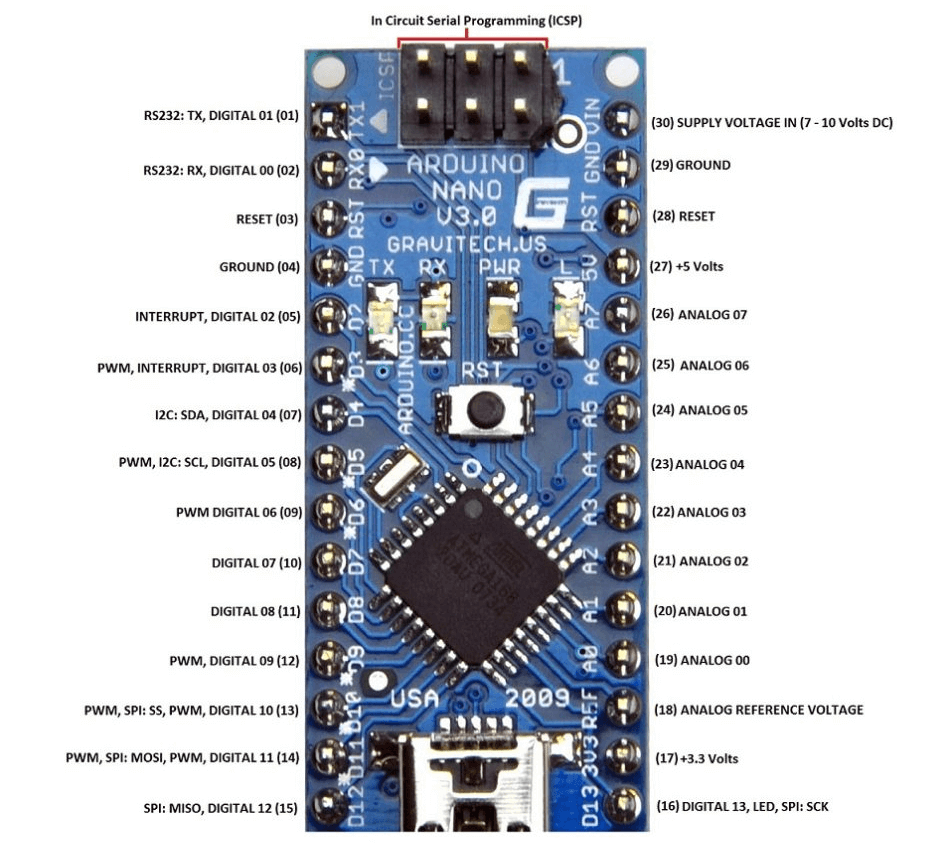
Figure 5: Arduino Nano Pinout
The Arduino Nano is a small and very popular microcontroller board, well-liked for its tiny size and ability to do many different things in DIY electronics projects. The pinout diagram of the Arduino Nano shows the various connections available on the board, each having a specific job:
VIN: Input for external power supply. This pin lets you connect an external power source to the board, providing the voltage the board needs to work.
GND: Ground connection. The ground pin completes the electrical circuit and helps keep the voltage levels steady across the board.
5V: Provides 5V power output. This pin gives a steady 5 volts of power to other parts connected to the board, such as sensors and modules.
3.3V: Provides 3.3V power output. Similar to the 5V pin, this one gives a steady 3.3 volts of power, which some sensors and devices need.
Digital I/O Pins: General-purpose input/output. These pins can be set to either read (input) or send (output) digital signals. They are used for connecting various parts like LEDs, buttons, and more.
Analog Input Pins: Reads analog signals. These pins can read different voltage levels, allowing the board to measure things like temperature, light intensity, and other analog signals.
PWM (Pulse Width Modulation): Used for simulating analog output. These special digital pins can act like an analog output by quickly turning the signal on and off, useful for controlling things like motor speed or LED brightness.
I2C (SDA, SCL): Communication between integrated circuits. These pins are used for I2C communication, a way for the Arduino to talk to other devices like sensors and displays using only two wires.
SPI (MISO, MOSI, SCK): Communication with serial peripheral devices. These pins are used for SPI communication, a fast way to exchange data between the Arduino and other devices like memory cards and displays.
UART (TX, RX): Communication for serial data. These pins are used for UART communication, a method for sending and receiving serial data, typically used for talking to computers or other microcontrollers.
Each pin on the Arduino Nano is numbered and has a specific job, making it easier to connect wires and write code for electronic projects. This setup makes building and programming your own electronic devices simpler, even if you are new to electronics.
RS-232 Pinout
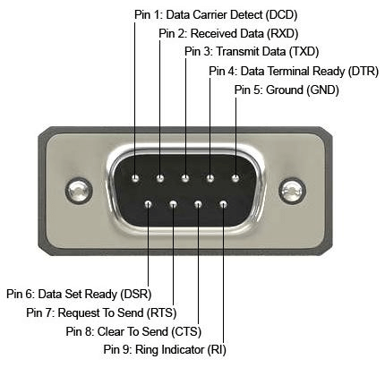
Figure 6: RS232 pinout
The RS-232 standard describes how to connect devices using serial communication. It is commonly used to connect computers to modems, printers, and other devices. The standard originally used a 25-pin connector, but a 9-pin connector is more common today. Each pin in the RS-232 connector has a specific job:
Pin 1 (DCD): Data Carrier Detect. This pin tells the device if a connection is established.
Pin 2 (RD): Received Data. This pin receives data from another device.
Pin 3 (TD): Transmitted Data. This pin sends data to another device.
Pin 4 (DTR): Data Terminal Ready. This pin signals that the device is ready to communicate.
Pin 5 (SG): Signal Ground. This pin is used as a common ground for all signals, helping to keep the connection stable.
Pin 6 (DSR): Data Set Ready. This pin indicates that the device on the other end is ready to communicate.
Pin 7 (RTS): Request to Send. This pin asks the other device for permission to send data.
Pin 8 (CTS): Clear to Send. This pin gives permission to the other device to send data.
Pin 9 (RI): Ring Indicator. This pin signals that the phone line is ringing.
Each pin has a specific role, making it easier to connect and use devices for serial communication.
PS/2 Pinout
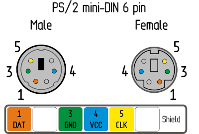
Figure 7: PS/2 Pinout
The PS/2 pinout refers to the 6-pin mini-DIN connector used for connecting keyboards and mice to computers. Each pin has a specific function:
Pin 1: Data. This pin sends the key data from the keyboard or mouse to the computer.
Pin 2: Not connected. This pin is not used.
Pin 3: Ground. This pin completes the electrical circuit and helps keep the voltage levels steady.
Pin 4: VCC (Power, +5 VDC). This pin provides the power needed for the keyboard or mouse to work.
Pin 5: Clock. This pin sends timing signals to help synchronize data communication between the keyboard or mouse and the computer.
Pin 6: Not connected. This pin is not used.
Each pin has a specific job, making it easier to understand how the keyboard or mouse talks to the computer.
ATX Power Supply Pinout
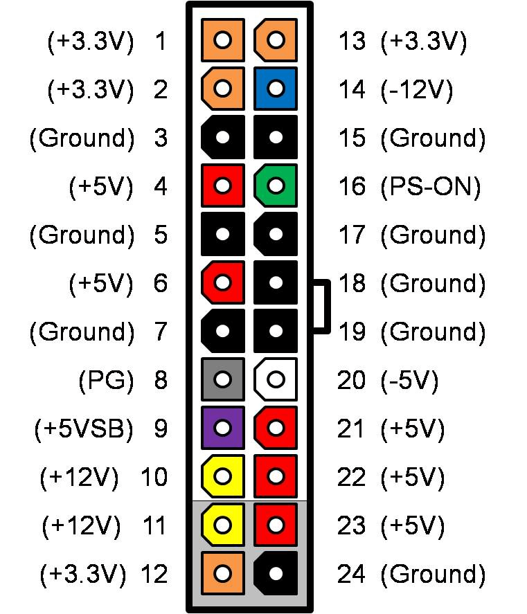
Figure 8: ATX Power Supply Pinout
The ATX power supply pinout is very useful for connecting power to computer motherboards. The 20-pin connector includes various color-coded pins, each having a specific job:
Pin 1 (orange): +3.3V. Supplies 3.3 volts.
Pin 2 (orange): +3.3V. Supplies 3.3 volts.
Pin 3 (black): Ground. Connects to ground.
Pin 4 (red): +5V. Supplies 5 volts.
Pin 5 (black): Ground. Connects to ground.
Pin 6 (red): +5V. Supplies 5 volts.
Pin 7 (black): Ground. Connects to ground.
Pin 8 (gray): Power Good. Indicates the power is good.
Pin 9 (purple): +5V standby. Supplies 5 volts even when the computer is off.
Pin 10 (yellow): +12V. Supplies 12 volts.
Pin 11 (orange): +3.3V. Supplies 3.3 volts.
Pin 12 (blue): -12V. Supplies negative 12 volts.
Pin 13 (black): Ground. Connects to ground.
Pin 14 (green): PS_ON. Turns the power supply on.
Pin 15 (black): Ground. Connects to ground.
Pin 16 (black): Ground. Connects to ground.
Pin 17 (black): Ground. Connects to ground.
Pin 18 (white): -5V (if present). Supplies negative 5 volts, if available.
Pin 19 (red): +5V. Supplies 5 volts.
Pin 20 (red): +5V. Supplies 5 volts.
Understanding the ATX pinout helps with assembling and troubleshooting desktop computers.
VGA Pinout
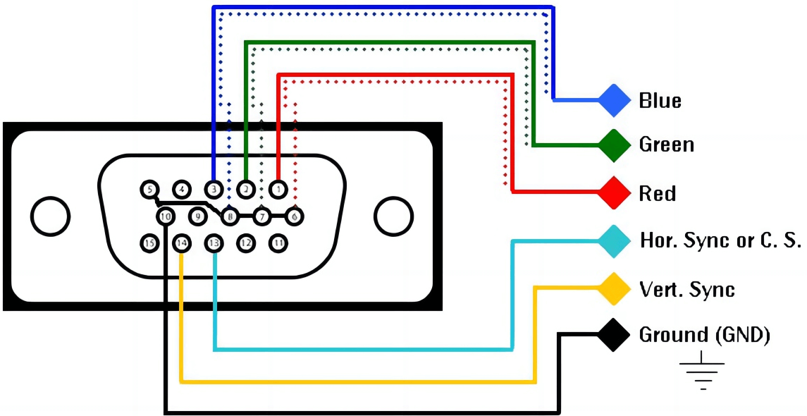
Figure 9: VGA Pinout
The VGA pinout explains the 15-pin connector used for video graphics arrays. Each pin has a specific job and is color-coded to handle different signals related to video transmission:
Pin 1: Red video. This pin carries the red color signal for the video.
Pin 2: Green video. This pin carries the green color signal for the video.
Pin 3: Blue video. This pin carries the blue color signal for the video.
Pin 4: Reserved. This pin is not used and is kept for future use.
Pin 5: Ground. This pin is connected to the ground to complete the circuit.
Pin 6: Red ground. This pin is the ground for the red color signal.
Pin 7: Green ground. This pin is the ground for the green color signal.
Pin 8: Blue ground. This pin is the ground for the blue color signal.
Pin 9: Key/PWR (not used). This pin is not used.
Pin 10: Ground. This pin is another ground connection to complete the circuit.
Pin 11: Monitor ID bit 0. This pin helps the computer identify the monitor.
Pin 12: Monitor ID bit 1/SDA. This pin helps the computer identify the monitor and is also used for data.
Pin 13: Horizontal Sync. This pin sends the horizontal sync signal to keep the image in line horizontally.
Pin 14: Vertical Sync. This pin sends the vertical sync signal to keep the image in line vertically.
Pin 15: Monitor ID bit 3/SCL. This pin helps the computer identify the monitor and is also used for clock signals.
Each pin's specific job makes sure that video signals are sent correctly from the computer to the monitor, so you get a clear and accurate picture.
Digital Visual Interface (DVI) Pinout
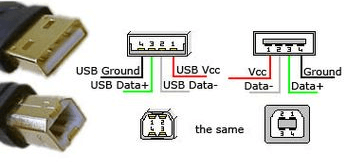
Figure 10: Digital Visual Interface (DVI) pinout
The DVI pinout is used for digital video connections, describing a 24-pin connector. Each pin has a specific job:
Pins 1-12: These are TMDS data pairs used for high-speed data transfer. They help move video data quickly.
Pins 13-16: These are TMDS clock pairs. They help keep the data transfer in sync.
Pins 17-24: These are ground and shield connections. They help keep the signal steady and reduce interference.
Additional pins: These are used for dual-link setups, allowing for higher resolutions.
The DVI pinout helps in sending clear and high-quality digital video.
Universal Serial Bus (USB) Pinout
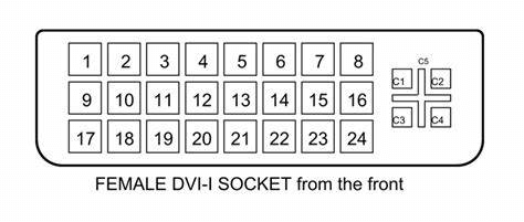
Figure 11: USB Pinout
The USB pinout for a typical USB Type-A connector has four color-coded pins, each with a specific job:
Pin 1 (red): +5V (power supply). This pin provides the power needed for the USB device to work.
Pin 2 (white): Data-. This pin is used for sending data from the USB device to the computer.
Pin 3 (green): Data+. This pin is used for receiving data from the computer to the USB device.
Pin 4 (black): Ground. This pin is used to complete the electrical circuit and helps keep the power levels steady.
These pins facilitate power delivery and data communication between USB devices and hosts.
Conclusion
Pinouts are helpful tools in electronics, providing clear guidance on connecting different parts correctly. Understanding pin numbers, names, descriptions, and connections helps prevent problems and makes sure devices work properly. By following the step-by-step guide and practical examples in this article, you can effectively read and use pinouts, whether working on simple DIY projects or more complicated tasks. Mastering pinouts improves your ability to fix, design, and create in the ever-changing world of electronics, leaving you well-prepared to handle any project with confidence.
Frequently Asked Questions [FAQ]
1. How do you read a pinout diagram?
Find the pin numbers and their positions on the diagram. Look for labels showing each pin's function, like power, ground, input, or output. Match each pin on the part with the diagram to ensure correct connections and avoid mistakes.
2. What is a pinout table?
A pinout table is a chart listing the pins of an electronic part or connector and their functions. It includes pin numbers, names, and descriptions, helping users understand and find the right connections.
3. What does pin mean in electrical?
In electrical terms, a pin is a small metal contact on an electronic part or connector. Each pin allows signals or power to flow in or out of the part. Pins are numbered and have specific functions like sending data, providing power, or grounding.
4. How do you pinout RJ45?
To pinout an RJ45 connector, arrange the eight wires in the T568A or T568B order. For T568B, the order is: white-orange, orange, white-green, blue, white-blue, green, white-brown, and brown. Insert the wires into the connector, ensure they are in the correct slots, and use a crimping tool to secure them.
5. What is the purpose of a pin?
The purpose of a pin in electronics is to connect electrical signals or power. Pins let different parts of a circuit or device communicate by sending data, voltage, or current. Each pin has a specific function to ensure the part or system works correctly.
About us
ALLELCO LIMITED
Read more
Quick inquiry
Please send an inquiry, we will respond immediately.
Magnetic Fields Decoded: Principles, Measurements, and Practical Uses
on July 1th

Decoding the Mechanics of Switch Poles and Throws
on July 1th
Popular Posts
-

What is GND in the circuit?
on January 1th 2933
-

RJ-45 Connector Guide: RJ-45 Connector Color Codes, Wiring Schemes, R-J45 Applications, RJ-45 Datasheets
on January 1th 2493
-

Fiber Connector Types: SC Vs LC And LC Vs MTP
on January 1th 2081
-

Understanding Power Supply Voltages in Electronics VCC, VDD, VEE, VSS, and GND
on November 8th 1883
-

Comparison Between DB9 and RS232
on January 1th 1759
-

What Is An LR44 Battery?
Electricity, that ubiquitous force, quietly permeates every aspect of our daily lives, from trivial gadgets to life-threatening medical equipment, it plays a silent role. However, truly grasping this energy, especially how to store and efficiently output it, is no easy task. It is against this background that this article will focus on a type of coin cell battery that may seem insignificant on the...on January 1th 1710
-

Understanding the Fundamentals:Inductance Resistance, andCapacitance
In the intricate dance of electrical engineering, a trio of fundamental elements takes center stage: inductance, resistance, and capacitance. Each bears unique traits that dictate the dynamic rhythms of electronic circuits. Here, we embark on a journey to decipher the complexities of these components, to uncover their distinct roles and practical uses within the vast electrical orchestra. Inductan...on January 1th 1651
-

CR2430 Battery Comprehensive Guide: Specifications, Applications and Comparison to CR2032 Batteries
What is CR2430 battery ?Benefits of CR2430 BatteriesNormCR2430 Battery ApplicationsCR2430 EquivalentCR2430 VS CR2032Battery CR2430 SizeWhat to look for when buying the CR2430 and equivalentsData Sheet PDFFrequently Asked Questions Batteries are the heart of small electronic devices. Among the many types available, coin cells play a crucial role, commonly found in calculators, remote controls, and ...on January 1th 1541
-

What Is RF and Why Do We Use It?
Radio Frequency (RF) technology is a key part of modern wireless communication, enabling data transmission over long distances without physical connections. This article delves into the basics of RF, explaining how electromagnetic radiation (EMR) makes RF communication possible. We will explore the principles of EMR, the creation and control of RF signals, and their wide-ranging uses. The article ...on January 1th 1537
-

CR2450 vs CR2032: Can The Battery Be Used Instead?
Lithium manganese batteries do have some similarities with other lithium batteries. High energy density and long service life are the characteristics they have in common. This kind of battery has won the trust and favor of many consumers because of its unique safety. Expensive tech gadgets? Small appliances in our homes? Look around and you'll see them everywhere. Among these many lithium-manganes...on January 1th 1504
HOT Part Number
-
IRFR3504TRPBF
Infineon Technologies
MOSFET N-CH 40V 30A DPAK
P4SMA15A
Bourns Inc.
TVS DIODE 12.8VWM 21.2VC DO214AC
IRFZ44S
Vishay Siliconix
MOSFET N-CH 60V 50A D2PAK
1534630
Phoenix Contact
CONN RCPT FMALE 4POS GOLD SOLDER
TLV2462CDRG4
Texas Instruments
IC OPAMP GP 2 CIRCUIT 8SOIC
XCS30-3TQ144I
AMD
IC FPGA 113 I/O 144TQFP
12102U300JAT2A
KYOCERA AVX
CAP CER 30PF 200V NP0 1210
CM150DU-24NFH
Powerex Inc.
IGBT MOD 1200V 150A 650W
AP7312-1833W6-7
Diodes Incorporated
IC REG LINEAR 1.8V/3.3V SOT26
AUIRS2113S
Infineon Technologies
IC GATE DRVR HALF-BRIDGE 16SOIC
A4915METTR-T
Allegro MicroSystems
IC MOTOR DRIVER 3V-5.5V 28QFN
SMDJ30A
Meritek
TVS DIODE 30VWM 48.4VC
MAX9218ECM+T
Analog Devices Inc./Maxim Integrated
IC DESERIALIZER LVDS 48-LQFP
STD70N02L
STMicroelectronics
MOSFET N-CH 25V 60A DPAK
AT42QT1070-MMH
Atmel
IC TOUCH SENSOR 7KEY 20-VQFN
R3112N431A-TR-FE
Nisshinbo Micro Devices Inc.
IC SUPERVISOR 1 CHANNEL SOT23-5
GRM0335C1ER20BA01D
Murata Electronics
CAP CER 0.2PF 25V C0G/NP0 0201
B72660M0301K072
EPCOS - TDK Electronics
VARISTOR 470V 1.2KA 2SMD JLEAD -
MC10EP52D
onsemi
IC FF D-TYPE SNGL 1BIT 8SOIC
SMBJ13A-E3/52
Vishay General Semiconductor - Diodes Division
TVS DIODE 13VWM 21.5VC DO214AA
IR21064SPBF
Infineon Technologies
IC GATE DRVR HI/LOW SIDE 14SOIC
LP2989ILD-1.8
Texas Instruments
FIXED POSITIVE LDO REGULATOR
MAX6806UR23+T
Analog Devices Inc./Maxim Integrated
IC SUPERVISOR 1 CHANNEL 8UMAX
A437M
Powerex Inc.
DIODE GEN PURP 600V 600A DO200AB
SIA914DJ-T1-GE3
Vishay Siliconix
MOSFET 2N-CH 20V 4.5A SC70-6
TL7705BCP
Texas Instruments
IC SUPERVISOR 1 CHANNEL 8DIP
FJX945YTF
onsemi
TRANS NPN 50V 0.15A SOT323
PIC16F1705-I/ST
Microchip Technology
IC MCU 8BIT 14KB FLASH 14TSSOP
RT8473GJ5
Richtek USA Inc.
IC LED DRV RGLTR PWM 1A TSOT23-5
EPF10K30RC240-3N
Intel
IC FPGA 189 I/O 240RQFP
2R5TPE330MAZB
Panasonic Electronic Components
CAP TANT POLY 330UF 2.5V 1411
TPA0172PWPR
Texas Instruments
IC AMP CLASS AB STER 2W 24HTSSOP
RT0805BRD0739RL
YAGEO
RES SMD 39 OHM 0.1% 1/8W 0805
SCA-4-10+
Mini-Circuits
RF PWR DVDR 5MHZ-1GHZ 10SMD
JMK325BJ476MMHT
Taiyo Yuden
CAP CER 47UF 6.3V X5R 1210
MP4020GS-LF-Z
Monolithic Power Systems Inc.
IC LED DRIVER 8SOIC -
ATSAMD21E16L-MNT
Microchip Technology
IC MCU 32BIT 64KB FLASH 32QFN
D2F-01L-D3
Omron Electronics Inc-EMC Div
SWITCH SNAP ACT SPDT 100MA 30V
NJM2794V-TE1
Nisshinbo Micro Devices Inc.
IC OPAMP ISOLATION 2 CIRC 14SSOP
IRFB3307ZGPBF
Infineon Technologies
MOSFET N-CH 75V 120A TO220AB
V375C8E100BG
Vicor Corporation
DC DC CONVERTER 8V 100W
LFE3-95EA-7FN1156I
Lattice Semiconductor Corporation
IC FPGA 490 I/O 1156FBGA
LMK107BJ105MA-T
Taiyo Yuden
CAP CER 1UF 10V X5R 0603
NM93CS66N
onsemi
IC EEPROM 4KBIT MICROWIRE 8DIP
LC4256C-75FT256AI
Lattice Semiconductor Corporation
IC CPLD 256MC 7.5NS 256FTBGA
FMS6G20US60
onsemi
IGBT MODULE 600V 20A 89W 25PMAA
MC33594FTA
Freescale Semiconductor
PLL TUNED UHF RECIEVER, PQFP24
SN65C1167NSR
Texas Instruments
IC TRANSCEIVER FULL 2/2 16SO
PIC32MZ2048EFM064-I/MR
Microchip Technology
IC MCU 32BIT 2MB FLASH 64QFN
1892711-2
TE Connectivity AMP Connectors
CONN PLUG 6POS EDGE MNT
CGA6M4X7R2J473M200AE
TDK Corporation
CAP CER 0.047UF 630V X7R 1210
CIH05T10NJNC
Samsung Electro-Mechanics
FIXED IND 10NH 300MA 420MOHM SMD
GRM0335C1HR50BA01D
Murata Electronics
CAP CER 0.5PF 50V C0G/NP0 0201
C0603X7R1A472K030BA
TDK Corporation
CAP CER 4700PF 10V X7R 0201