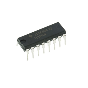
TL494CN PWM Controller: Pin Layout and How it Works?
The TL494CN PWM Controller is a multifaceted component in power management, extensively utilized across various switching power supply systems. Its reputation for adaptability stems from seamlessly integrating functions, which optimize both efficiency and performance. The controller exhibits a sturdy design, capable of functioning within an operational temperature range of -40°C to 85°C. This article will explore the TL494CN’s features, specifications, and applications. It will provide deeper insights into the controller's relevance in modern electronic designs.Catalog
What is the TL494CN PWM Controller?
The TL494CN is a versatile fixed-frequency pulse width modulation (PWM) controller extensively used in different switching power systems, such as half-bridge, full-bridge, and single-ended forward dual-tube configurations. This controller incorporates power control functions, offering the flexibility to adapt to specific needs. With its two 200mA PWM outputs and the ability to operate at a switching frequency of up to 300 kHz, it provides precise control and improved efficiency. Its strong design ensures reliable operation within a temperature range of -40°C to 85°C and supports a power supply voltage between 7V and 40V, offering adaptability for various power sources.
Replacement and Equivalent of TL494CN PWM Controller
• SG3525
• TL494CDR
• TL494CNE4
• UC3843
TL494CN Symbol, Footprint and Pin Configuration
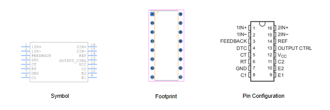
The TL494CN Pulse Width Modulation (PWM) controller has 16 pins, each designated for specific functions integral to its operation:
Pin 1 (IN+): This serves as the non-inverting input of Error Amplifier 1. It plays a role in transforming the analog signal into a compatible digital format, an important step towards error correction and precision.
Pin 2 (IN-): The inverting input of Error Amplifier 1, pairing with Pin 1 to provide contrast to the signal. This balance allows for effective management of error corrections, ensuring the system remains stable.
Pin 3 (FEEDBACK): Captures the feedback from outputs. This enables real-time adjustments, maintaining voltage regulation and system stability, addressing the system's adaptability to changing conditions.
Pin 4 (DTC): Known as the Dead-Time Control Comparator Input, this pin manages the dead-time interval. It prevents potential overlap in switching, good for achieving efficiency and longevity in power electronics applications.
Pin 5 (CT): The Capacitor Terminal for frequency setting. Alongside Pin 6, it determines the oscillation frequency, which directly impacts the timing characteristics of PWM signals.
Pin 6 (RT): The Resistor Terminal for frequency setting. In conjunction with Pin 5 (CT), it fine-tunes the operating frequency, ensuring the controller performs optimally and maintains compatibility with external components.
Pin 7 (GND): The ground pin completes the electrical circuit by providing a common return path for electric current, enhancing safety and stability.
Pin 8 (C1): The output 1 collector. It connects to the output stage of the power supply, allowing it to drive loads with efficiency.
Pin 9 (E1): Output 1 emitter, works in tandem with Pin 8 (C1) to form a half-bridge driver circuit, use in power conversion applications. This pairing enhances the circuit's functionality and performance.
Pin 10 (E2): The output 2 emitter shares similarities with Pin 9 (E1). It is use for dual-output functionalities, which are common in PWM applications requiring balanced outputs.
Pin 11 (C2): Complements Pin 10 (E2) as the output 2 collector, completing the second half-bridge circuit. This configuration is good for efficient and balanced power supply designs.
Pin 12 (VCC): Provides the positive power supply to energize the internal circuitry of the TL494CN. This ensures the controller operates with robustness and reliability.
Pin 13 (OUTPUT CTRL): Facilitates Output Mode Selection. This pin allows customization of the controller’s output configuration to meet specific application requirements, enhancing adaptability and functionality.
Pin 14 (REF): Supplies a 5V regulated reference. This stabilization is important for precise PWM control, underpinning the controller's accuracy and reliability.
Pin 15 (2IN-): The inverting input of Error Amplifier 2, forming a pair with Pin 16. This manages additional error correction processes, enhancing the controller’s ability to maintain system integrity.
Pin 16 (2IN+): The non-inverting input of Error Amplifier 2. It works alongside Pin 15 to handle differential inputs, playing a role in ensuring accuracy in error amplification and overall system performance.
Specifications of the TL494CN PWM Controller
|
Product Attribute |
Attribute Value |
|
Manufacturer |
Texas Instruments |
|
Package / Case |
PDIP-16 |
|
Packaging |
Tube |
|
Length |
19.3 mm |
|
Width |
6.35 mm |
|
Height |
4.57 mm |
|
Output Current |
200 mA |
|
Input Voltage |
7 V ~ 40 V |
|
Output Voltage |
40 V |
|
Pin Count |
16 |
|
Switching Frequency |
300 kHz |
|
Rise Time |
100 ns |
|
Fall Time |
40 ns |
|
Operating Temperature |
-40°C ~ 85°C |
|
Mounting Style |
Through Hole |
|
Number of Outputs |
2 Output |
|
Product Type |
Switching Controllers |
Features and Benefits of the TL494CN PWM Controller
Integrated Error Amplifier
The TL494CN’s error amplifier excels in precise regulation by comparing the output voltage against a reference level. This enables any adjustments to maintain the targeted output. This mechanism is valuable in power supply systems for ensuring voltage stability amidst varying load conditions. Many practical applications demonstrate the TL494CN's robustness in maintaining consistent power delivery, preventing fluctuations that could otherwise compromise performance.
High-Performance Internal Voltage Regulator
The internal voltage regulator of the TL494CN produces a stable 5V output with a tight tolerance of ±5%. This regulator provides a reliable reference voltage for various internal and external components. Proven through countless electronic designs, this stability supports long-term device functionality.
Built-In Power Transistor
A notable feature is its integrated power transistor capable of handling up to 500mA in push/pull mode. This ability is advantageous in driving bipolar switching transistors, allowing efficient power transfer with minimized thermal dissipation. In higher-power applications, the efficiency of power handling and thermal management influences system effectiveness and longevity, making this feature quite compelling.
Standalone Sawtooth Wave Oscillator
The TL494CN incorporates a standalone sawtooth wave oscillator, for generating the PWM signal. The oscillator frequency can be precisely calculated using the formula:
![]()
Precision in frequency control is use for applications such as communication systems and sophisticated motor control circuits.
Advanced Dead-Time Control
Advanced dead-time control in the TL494CN ensures adequate switching-off time for power transistors before the next cycle. This helps prevent simultaneous conduction, which could cause short circuits. This feature holds particular value in industrial power systems, where rigorous safety standards are upheld.
Comprehensive PWM Power Control
The TL494CN complete PWM power control by integrating all circuits within a single chip. This integration simplifies design, reduces reliance on external components, and enhances system reliability.
MOSFET External Circuit Sinking
For applications requiring external circuit sinking for MOSFETs, the TL494CN's design excels in managing power within complex electronic systems. This leads to more efficient and compact power supply designs, emphasizing the controller's versatility and effectiveness.
What are the Layout for TL494CN PWM Controller?
When designing your PCB, it's require to place external compensation components close to the IC for better functionality. Utilizing surface-mount technology (SMT) reduces unwanted inductance and keeps the layout solid, improving performance by minimizing physical distances in circuits. For high-current power traces, keep them short and follow a guideline of at least 15 mils in width for every ampere of current. Positioning inductors, output capacitors, and diodes close together limits electromagnetic interference (EMI) and noise, especially in high-reliability power supply designs. Using ground planes on both sides of the PCB helps reduce loop errors and EMI, while separating power and signal planes in multilayer boards minimizes cross-talk. Ensure vias can handle around 200mA each for stable current flow. To maintain consistent current flow and minimize EMI, feedback traces should avoid inductors and noisy power traces, ideally running on the opposite side of the PCB, shielded by a ground plane. Finally, place low-value ceramic input capacitors near the IC’s VCC pin to ensure stable internal voltage, favoring surface-mount capacitors for their lower inductance and noise reduction. Crafting an effective layout for the TL494CN combines technical diligence with an understanding of proven design principles across various applications.
Absolute Maximum Ratings of TL494CN PWM Controller
|
Parameter |
Min |
Max |
Unit |
|
Supply voltage (Vcc) |
41 |
V |
|
|
Amplifier input voltage (Vi) |
Vcc + 0.3 |
V |
|
|
Collector output voltage (Vo) |
41 |
V |
|
|
Collector output current (Io) |
250 |
mA |
|
|
Lead temperature 1.6 mm (1/16 inch) from case for 10
seconds |
260 |
°C |
|
|
Storage temperature range (Tstg) |
-65 |
150 |
°C |
Operational Mechanism of TL494CN PWM Controller
Fixed Frequency PWM System
The TL494CN employs a fixed frequency PWM (Pulse Width Modulation) system, orchestrated by a linear sawtooth oscillator. This oscillator's frequency can be adjusted through the selection of specific external resistors and capacitors. Fine-tuning these components allow to achieve precise control over the PWM signal, effectively addressing specific requirements in various electronic applications.
Sawtooth Oscillator and Control Signals
The TL494CN's functionality revolves around the interaction between the sawtooth waveform generated by its oscillator and various control signals. These control signals may emerge from several sources, including feedback loops in voltage regulation systems. When the sawtooth output is compared with these control signals, it precisely regulates the duty cycle of the PWM output.
Regulation through NOR Gate and Power Transistors
Regulation within the TL494CN involves a NOR gate, which manages the switching of power transistors Q1 and Q2. This gate modulates the transistors' operations to uphold stability and efficiency in power output. The prescribed gating process involves clocking the signals low. Such a technique frequently results in smoother transitions and reduced signal noise, thereby enhancing overall performance in power management.
Pulse Width Modulation Dynamics
The dynamics of pulse width modulation in the TL494CN reveal an inversely proportional relationship between the control signal amplitude and the output pulse width. As the amplitude of the control signal rises, the width of the output pulse narrows. This dynamic attribute is use for applications requiring precise modulation, such as motor speed controls and power supplies.
Applications of the TL494CN PWM Controller
Electric Bicycles
In electric bicycles, the TL494CN is use for power management systems. By controlling motor functioning, it prolongs battery life and elevates efficiency. It shows that optimizing the PWM signal can increase travel range and mitigate overheating concerns, illustrating its impact on electric transport solutions.
Microwave Ovens
For microwave ovens, the TL494CN regulates power to the magnetron, ensuring uniform cooking. Its robustness under strenuous conditions further validates its application in home appliances.
Smoke Detectors
Smoke detectors leverage the TL494CN’s power regulation capabilities, for battery-operated units that demand longevity and reliable performance. Advanced designs using this controller can cut down power usage, greatly extending battery life that directly correlates with safety and ease of maintenance.
Server Power Supplies
Server power supplies incorporate the TL494CN for its accurate voltage regulation and energy-efficient power conversion. Practical optimization has demonstrated that elevated efficiency translates to lower operational costs and heightened server reliability, factors for data centers.
Desktop Computers
In desktop computers, the TL494CN is found in power supply units to maintain stable voltage levels for delicate components. This stability bolsters overall system reliability and lifespan. With this controller it show fewer component failures and better processing efficiency.
Solar Inverters and Microinverters
The TL494CN is instrumental in solar inverters and microinverters, playing a part in sustainable energy technologies. By effectively managing DC to AC conversion, it maximizes solar energy use and system efficiency. Controllers like the TL494CN are integral to improving the performance and dependability of solar power systems, fostering broader adoption of renewable energy.
Frequently Asked Questions [FAQ]
1. What is the purpose of TL494CN?
The TL494CN aims to regulate constant current by tweaking output voltage. Its sophisticated architecture includes various essential components enabling it to maintain consistent power output for diverse needs. Specifically, output control circuit, flip-flop, dead-time comparator, two error amplifiers, 5V reference voltage, oscillator, and PWM comparator.
2. What are TL494CN's protection features?
Ensuring circuit integrity, the TL494CN boasts multiple protection features such as over-current protection, over-temperature protection, and short-circuit protection. These safeguards effectively prevent faults and overloads. They are valuable in environments like industrial control systems, where reliability and longevity are require to avoid potential damage and operational downtime.
3. What is the operating temperature range of TL494CN?
The TL494CN can operate within a temperature range of -40°C to 85°C. This wide operational spectrum guarantees dependable performance under various conditions, whether in severe cold or intense heat. It is adaptable to different geographical areas and industrial scenarios.
4. What are the typical applications of TL494CN?
TL494CN finds extensive use in several fields, including switched-mode power supplies, inverters, motor control, lighting control, and other PWM systems. Its adaptability makes it ideal for a variety of applications. In renewable energy systems, plays a main role in power management. In automotive electrical systems, it ensures robust and efficient power conversion to vehicle performance.
5. How does TL494CN work?
The TL494CN facilitates precise PWM control by comparing internal oscillator sawtooth waveforms with control signals. This nuanced modulation of output pulses is use for tasks requiring power regulation. For instance, in variable speed drives for motors, this mechanism allows for accurate control over speed and torque, enhancing both performance and energy efficiency.
About us
ALLELCO LIMITED
Read more
Quick inquiry
Please send an inquiry, we will respond immediately.
LM393M Comparator: Alternatives, Features, and PCB Layout Tips
on September 27th
TLP250 Driver for MOSFET and IGBT: Manufacturer Overview, Footprint, and Application Guide
on September 27th
Popular Posts
-

What is GND in the circuit?
on January 1th 3120
-

RJ-45 Connector Guide: RJ-45 Connector Color Codes, Wiring Schemes, R-J45 Applications, RJ-45 Datasheets
on January 1th 2679
-

Understanding Power Supply Voltages in Electronics VCC, VDD, VEE, VSS, and GND
on November 15th 2228
-

Fiber Connector Types: SC Vs LC And LC Vs MTP
on January 1th 2187
-

Comparison Between DB9 and RS232
on January 1th 1804
-

What Is An LR44 Battery?
Electricity, that ubiquitous force, quietly permeates every aspect of our daily lives, from trivial gadgets to life-threatening medical equipment, it plays a silent role. However, truly grasping this energy, especially how to store and efficiently output it, is no easy task. It is against this background that this article will focus on a type of coin cell battery that may seem insignificant on the...on January 1th 1778
-

Understanding the Fundamentals:Inductance Resistance, andCapacitance
In the intricate dance of electrical engineering, a trio of fundamental elements takes center stage: inductance, resistance, and capacitance. Each bears unique traits that dictate the dynamic rhythms of electronic circuits. Here, we embark on a journey to decipher the complexities of these components, to uncover their distinct roles and practical uses within the vast electrical orchestra. Inductan...on January 1th 1731
-

CR2430 Battery Comprehensive Guide: Specifications, Applications and Comparison to CR2032 Batteries
What is CR2430 battery ?Benefits of CR2430 BatteriesNormCR2430 Battery ApplicationsCR2430 EquivalentCR2430 VS CR2032Battery CR2430 SizeWhat to look for when buying the CR2430 and equivalentsData Sheet PDFFrequently Asked Questions Batteries are the heart of small electronic devices. Among the many types available, coin cells play a crucial role, commonly found in calculators, remote controls, and ...on January 1th 1682
-

What Is RF and Why Do We Use It?
Radio Frequency (RF) technology is a key part of modern wireless communication, enabling data transmission over long distances without physical connections. This article delves into the basics of RF, explaining how electromagnetic radiation (EMR) makes RF communication possible. We will explore the principles of EMR, the creation and control of RF signals, and their wide-ranging uses. The article ...on January 1th 1672
-

Comprehensive guide to hFE in transistors
Transistors are crucial components in modern electronic devices, enabling signal amplification and control. This article delves into the knowledge surrounding hFE, including how to select a transistor's hFE value, how to find hFE, and the gain of different types of transistors. Through our exploration of hFE, we gain a deeper understanding of how transistors work and their role in electronic circu...on November 15th 1640
HOT Part Number
-

RD6.2P-T1-AZ
Renesas
RD6.2P - 1W ZENER DIODE
PS9122-F3-N-AX
Renesas Electronics America Inc
OPTOISO 3.75KV OPN COLLECTOR 5SO
WSL2512R0300FTB
Vishay Dale
RES 0.03 OHM 1% 1W 2512
NJM1496V-TE2
Nisshinbo Micro Devices Inc.
IC MOD/DEMOD BIPO DBL BAL 14SSOP
ADG201HSKP
Analog Devices Inc.
IC SWITCH SPST-NCX4 50OHM 20PLCC
TLV62568DBVT
Texas Instruments
IC REG BUCK ADJ 1A SOT23-5
SN65HVD485EP
Texas Instruments
IC TRANSCEIVER HALF 1/1 8DIP
RT0402BRD0710KL
Yageo
RES SMD 10K OHM 0.1% 1/16W 0402
93LC56A-I/ST
Microchip Technology
IC EEPROM 2KBIT MICROWIRE 8TSSOP
XCV800-4BG560C
AMD
IC FPGA 404 I/O 560MBGA
AQV216EH
Panasonic Electric Works
SSR RELAY SPST-NO 50MA 0-600V
BH1710FVC-TR
Rohm Semiconductor
SENSOR OPT 560NM AMBIENT 6WSOF
MTM231232LBF
Panasonic Electronic Components
MOSFET P-CH 20V 3A SMINI3-G1-B
XC6VCX240T-2FFG1156I
AMD
IC FPGA 600 I/O 1156FCBGA
UPG2164T5N-E2-A
Renesas Electronics America Inc
DPDT, 2400MHZ MIN, 6000MHZ MAX,
AD7405BRIZ
Analog Devices Inc.
IC MODULATOR 16BIT 16SOIC
NCP114AMX120TCG
onsemi
IC REG LINEAR 1.2V 300MA 4UDFN
NSBA144EF3T5G
onsemi
TRANS PREBIAS PNP 50V SOT1123 -
0881060.UR
Littelfuse Inc.
FUSE BOARD MOUNT 60A 75VDC 2SMD
MPSW63
onsemi
TRANS PNP DARL 30V 0.5A TO92
PIC16F1933-I/MV
Microchip Technology
IC MCU 8BIT 7KB FLASH 28UQFN
LT3070MPUFD#PBF
Analog Devices Inc.
IC REG LIN POS PROG 5A 28QFN
1206ZC155KAT2A
KYOCERA AVX
CAP CER 1.5UF 10V X7R 1206
RT0805DRE07147RL
YAGEO
RES SMD 147 OHM 0.5% 1/8W 0805
MCP79410T-I/MNY
Microchip Technology
IC RTC CLK/CALENDAR I2C 8TDFN
ISO3082DWG4
Texas Instruments
ISO RS485/422 0.2MBPS 2.5KVRMS
MAX506BCWP
Analog Devices Inc./Maxim Integrated
IC DAC 8BIT V-OUT 20SOIC
ADS8508IBDW
Texas Instruments
IC ADC 12BIT SAR 20SOIC
AOT2618L
Alpha & Omega Semiconductor Inc.
MOSFET N-CH 60V 7A/23A TO220
BUT11A
onsemi
TRANS NPN 450V 5A TO220-3
TPS22924DYZPT
Texas Instruments
IC PWR SWITCH N-CHAN 1:1 6DSBGA
TMS320C6657CZH25
Texas Instruments
IC DSP FIX/FLOAT POINT 625FCBGA
BMA253
Bosch Sensortec
ACCELERATION DIGITAL, TRIAXIAL S
SM6T27AY
STMicroelectronics
TVS DIODE 23.1VWM 48.3VC SMB
74ACT241SCX
onsemi
IC BUF NON-INVERT 5.5V 20SOIC
CS497024-CVZ
Cirrus Logic Inc.
IC DSP 32BIT HD DECODER 128LQFP -

VI-J3Z-EX
Vicor Corporation
DC DC CONVERTER 2V 30W
LM3S3826-IQR50-C3
Texas Instruments
IC MCU 32BIT 256KB FLASH 64LQFP
TST-105-01-S-D-LL
Samtec Inc.
CONN HEADER VERT 10POS 2.54MM
LTC6655CHMS8-2.5#TRPBF
Analog Devices Inc.
IC VREF SERIES 0.05% 8MSOP
SST25VF032B-80-4I-S2AF
Microchip Technology
IC FLASH 32MBIT SPI 80MHZ 8SOIC
DS1804Z-050+T&R
Analog Devices Inc./Maxim Integrated
IC DGTL POT 50KOHM 100TAP 8SOIC
OP490FY
Analog Devices Inc.
IC OPAMP GP 4 CIRCUIT 14CERDIP
HMC736LP4ETR
Analog Devices Inc.
IC MMIC VCO HBT HALF FREQ 24-QFN
XC9536XL-10VQ64C
AMD
IC CPLD 36MC 10NS 64VQFP
74VHC4053M
Fairchild Semiconductor
IC SWITCH SPDT X 3 100OHM 16SOIC
GRM2196T2A4R7CD01D
Murata Electronics
CAP CER 4.7PF 100V T2H 0805
JANTX1N6463US
Semtech Corporation
DIODE ZENER 12V 500W SM
KSD1621UTF
Fairchild Semiconductor
TRANS NPN 25V 2A SOT89-3
LM101AH
Texas Instruments
IC OPAMP GP 1 CIRCUIT TO99-8
TSOP36336FTT
Vishay Semiconductor Opto Division
IC SENSOR REMOTE OPTICAL
MKP386M468125JT5
Vishay Beyschlag/Draloric/BC Components
CAP FILM 0.68UF 5% 1.25KVDC SCRW
SN75DP118RHHT
Texas Instruments
IC REDRIVER DISPLAYPORT 36VQFN
EP1K30FC256-3N
Altera (Intel® Programmable Solutions Group)
IC FPGA 171 I/O 256FBGA