IRF730 Transistor: Comprehensive Guide to Datasheet, Pinout, and Applications
The IRF730, an N-channel MOSFET available in TO-220 and TO-220AB packages, stands out for its reliability and efficiency in handling high voltages across various electronic applications. In this article, we dive into a comprehensive analysis of the IRF730, exploring its technical features, actual uses in automotive and communication systems, and useful design considerations. Whether you're managing power distribution or building robust circuits, the IRF730’s low on-resistance, high-speed switching, and superior thermal performance make it a valuable component in power management systems.Catalog
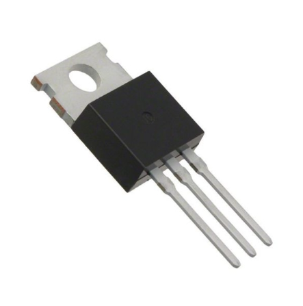
Pinout of IRF730
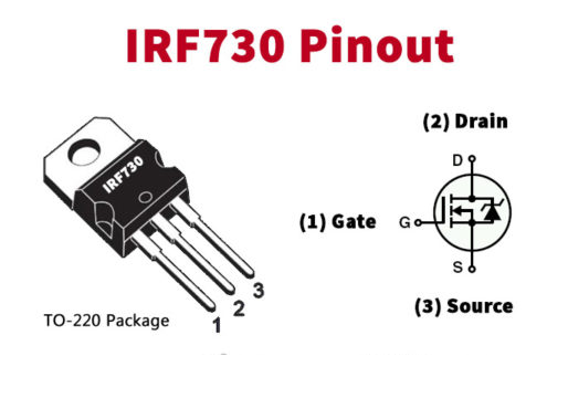
CAD Model of IRF730
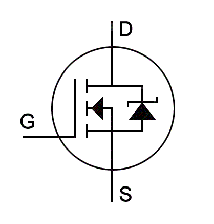
IRF730 Symbol
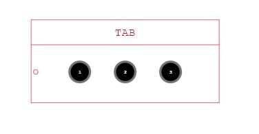
IRF730 Footprint
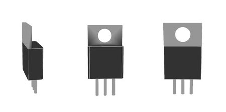
IRF730 3D Model
IRF730 Overview
The IRF730 is a robust N-channel MOSFET, versatile in its applications due to its sturdy construction and high efficiency. Encased in both TO-220 and TO-220AB packages, this component can manage a continuous drain current up to 5.5A at 400V. It thrives in demanding electronic environments, efficiently dissipating power with a capability of up to 75W and supporting a pulsed drain current of 22A. This makes the IRF730 a reliable choice for various high-stress scenarios, demonstrating its strength and resilience.
The IRF730’s ability to handle notable electrical loads makes it mainly suited for high-power audio amplifiers. In these settings, the MOSFET's characteristics ensure minimal signal distortion and reliable performance under strenuous conditions—a lifeline for striving for perfect sound. This is used in audio equipment where consistent sound quality is dominant. Practical deployment in amplifier circuits illustrates that devices like the IRF730 greatly contribute to achieving desired output fidelity, especially in audio environments.
The experience emphasizes the importance of integrating the IRF730 into circuits with careful thermal management. Strategies like heat sinking and designing the PCB to maximize heat dissipation are often employed to meet these needs. You can note that optimizing these aspects can extremely extend the lifespan and performance reliability of the MOSFET, making it a staple in their toolkits. Additionally, selecting the appropriate gate drive voltage and ensuring proper isolation in high-voltage applications is required to avoid potential failures, demanding meticulous attention to detail and thorough planning.
Manufacturer of IRF730
STMicroelectronics thrives as a semiconductor powerhouse, widely recognized for its mastery of silicon and system development. The company excels in System-on-Chip (SoC) technology, backed by comprehensive manufacturing prowess, and an extensive IP portfolio that aligns with the evolving needs of contemporary electronics.
The expertise of STMicroelectronics in SoC technology forms the ultimate pillar of its accomplishments. SoCs cleverly amalgamate various elements—processors, memory units, and peripherals—onto a single chip, which optimizes space and enhances performance. This thoughtful integration significantly minimizes power consumption and boosts efficiency, attributes that are basic for modern, compact, and portable devices. The company's innovations in this area demonstrate an exact understanding of how to harmoniously balance these serious components.
The robust manufacturing capabilities of STMicroelectronics underpin its ability to produce high-quality semiconductor products. With state-of-the-art fabrication facilities, known as fabs, the company imposes meticulous quality control throughout the entire production process. This meticulousness ensures consistency and reliability, which are dominant in the fiercely competitive tech industry. The practical upshot of these capabilities is extended product life cycles and minimized defect rates, leading to heightened customer satisfaction.
Features of IRF730
|
Feature |
Specification |
|
Package
Type |
TO-220AB,
TO-220 |
|
Transistor
Type |
N
Channel |
|
Max Voltage
(Drain to Source) |
400V |
|
Max
Gate to Source Voltage |
±20V |
|
Max
Continuous Drain Current |
5.5A |
|
Max
Pulsed Drain Current |
22A |
|
Max
Power Dissipation |
75W |
|
Minimum
Voltage to Conduct |
2V
to 4V |
|
Max
Storage & Operating Temperature |
-55
to +150℃ |
IRF730 Alternatives
Applications of IRF730
The IRF730 is a versatile component that excels in various contexts, especially in high-voltage environments, demonstrating an ability to adapt and perform efficiently. Its robust nature supports driving loads up to 5.5A and integrates easily with ICs, microcontrollers, and popular development platforms like Arduino and Raspberry Pi.
High-Voltage Applications
The IRF730 shines in high-voltage scenarios by managing remarkable voltage levels with precision and reliability. This feature finds application in industrial automation systems, where consistent and precise power control elements keep operations smooth. These systems often depend on such performance to minimize downtime and ensure operational stability. Industrial automation systems emphasize consistent power control, precise operation, and enhance operational stability.
General-Purpose Contexts
In general-purpose applications, the IRF730 stands out for its flexibility. It finds use in switching regulators, motor drivers, and various circuit designs, providing dependable performance. This versatility is invaluable in educational settings, where it aids you in exploring and implementing a range of electronic principles. Notable uses in general-purpose contexts are in switching regulators, motor drivers, and educational projects.
Interface with ICs and Microcontrollers
Effective interfacing with ICs and microcontrollers is a notable benefit of the IRF730. This compatibility makes it a preferred component in many embedded systems. For instance, in smart home devices, the IRF730 drives actuators and sensors, enabling coordinated and efficient operations under the guidance of a central microcontroller. Applications in embedded systems are smart home devices and actuator and sensor control.
Integration with Development Platforms
Development platforms such as Arduino and Raspberry Pi gain significantly from the IRF730’s capabilities. Often used in prototyping and development, these platforms need components that can maintain performance across rapid development cycles. The reliable performance of the IRF730 aids you in swiftly creating stable designs. Development platforms benefit from prototyping environments, rapid development cycles, and reliable development cycles.
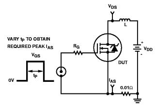
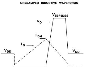
Test Circuit of IRF730
Ensuring the Longevity of the IRF730
Ensuring the IRF730 functions efficiently over the long haul involves more than merely avoiding its maximum rated capacity. Pushing any component to its upper limit not only induces undue stress but also risks eventual failure. Instead, a more prudent approach is to operate the IRF730 at approximately 80% of its rated capabilities. This provides a safety buffer that bolsters its reliability and stability.
Limiting load voltage to 320V, substantially below its peak capacity, is crucial in preventing breakdowns under high-stress conditions. Similarly, controlling the continuous current to a maximum of 4.4A and the pulsed current to 17.6A effectively mitigates thermal and electrical stress. From a pragmatic perspective, this strategy adheres to established hardware design best practices, where derating components ensures their longevity and performance consistency in real-world applications.
Maintaining proper operating temperatures is used for the IRF730. The recommended temperature range spans from -55°C to +150°C. Staying within this band ensures that the semiconductor material functions at its best, reducing the likelihood of thermal runaway or other heat-related failures Experiences indicate that continually monitoring and regulating temperatures within these parameters can greatly enhance the lifespan of electronic components, including the IRF730.
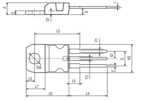
Packaging of IRF730
Similar Components
|
Type |
Parameter |
|
Mount |
Through Hole |
|
Mounting Type |
Through Hole |
|
Package / Case |
TO-220-3 |
|
Number of Pins |
3 |
|
Transistor Element Material |
Silicon |
|
Current - Continuous Drain (Id) @ 25℃ |
5.5A Tc |
|
Drive Voltage (Max Rds On, Min Rds On) |
10V |
|
Number of Elements |
1 |
|
Power Dissipation (Max) |
100W Tc |
|
Turn Off Delay Time |
15 ns |
|
Operating Temperature |
150°C TJ |
|
Packaging |
Tube |
|
Series |
PowerMESH™ II |
|
JESD-609 Code |
e3 |
|
Part Status |
Obsolete |
|
Moisture Sensitivity Level (MSL) |
1 (Unlimited) |
|
Number of Terminations |
3 |
|
ECCN Code |
EAR99 |
|
Terminal Finish |
Matte Tin (Sn) |
|
Additional Feature |
High Voltage, Fast Switching |
|
Voltage - Rated DC |
400V |
|
Current Rating |
5.5A |
|
Base Part Number |
IRF7 |
|
Pin Count |
3 |
|
Voltage |
400V |
|
Element Configuration |
Single |
|
Current |
55A |
|
Operating Mode |
Enhancement Mode |
|
Power Dissipation |
100W |
|
FET Type |
N-Channel |
|
Transistor Application |
Switching |
|
Rds On (Max) @ Id, Vgs |
1 Ω @ 3A, 10V |
|
Vgs(th) (Max) @ Id |
4V @ 250μA |
|
Input Capacitance (Ciss) (Max) @ Vds |
530pF @ 25V |
|
Gate Charge (Qg) (Max) @ Vgs |
24nC @ 10V |
|
Rise Time |
11 ns |
|
Vgs (Max) |
±20V |
|
Fall Time (Typ) |
9 ns |
|
Continuous Drain Current (ID) |
5.5A |
|
JEDEC-95 Code |
TO-220AB |
|
Gate to Source Voltage (Vgs) |
20V |
|
Drain-source On Resistance-Max |
1Ω |
|
Drain to Source Breakdown Voltage |
400V |
|
Feedback Cap-Max (Crss) |
65 pF |
|
Radiation Hardening |
No |
|
RoHS Status |
ROHS3 Compliant |
|
Lead Free |
Contains Lead |
Datasheet PDF
IRF730 Datasheets:
Frequently Asked Questions [FAQ]
1. What is IRF730?
The IRF730 is a high-performance N-channel MOSFET available in TO-220 and TO-220AB packages. Supporting up to 5.5A at 400V, it dissipates 75W and handles 22A of pulsed current. This feature makes it valuable for high-power audio amplifiers and other serious applications. You can often find it highly effective in circuits that prioritize high efficiency and reliability.
2. What are the primary applications of IRF730?
Primarily designed for high-speed switching, the IRF730 is suitable for use in uninterruptible Power Supply (UPS) systems, DC-DC converters, telecommunication equipment, lighting systems, and various industrial applications. Its low gate drive power requirement is an asset in scenarios where minimizing energy consumption is a must. For instance, in demanding industrial environments, its robustness ensures reliable long-term operation.
3. What conditions does IRF730 operate?
Optimal conditions for the IRF730 include.
Maximum drain-source voltage: 400V
Maximum gate-source voltage: ±20V
Maximum continuous drain current: 5.5A
Maximum pulsed drain current: 22A
Power dissipation cap: 75W
Conduction voltage range: 2V to 4V
Operating and storage temperatures: -55 to +150°C
Experienced emphasize that adhering to these parameters is active for maximizing the performance and lifespan of the IRF730, highlighting the necessity of proper thermal management and voltage regulation.
About us
ALLELCO LIMITED
Read more
Quick inquiry
Please send an inquiry, we will respond immediately.
1N5407 Diode: Equivalents, Applications, and Datasheet
on October 17th
LM311N Voltage Comparator: Features, Pinout, and Datasheet
on October 17th
Popular Posts
-

What is GND in the circuit?
on January 1th 3272
-

RJ-45 Connector Guide: RJ-45 Connector Color Codes, Wiring Schemes, R-J45 Applications, RJ-45 Datasheets
on January 1th 2815
-

Understanding Power Supply Voltages in Electronics VCC, VDD, VEE, VSS, and GND
on November 20th 2642
-

Fiber Connector Types: SC Vs LC And LC Vs MTP
on January 1th 2265
-

Comparison Between DB9 and RS232
on January 1th 1882
-

What Is An LR44 Battery?
Electricity, that ubiquitous force, quietly permeates every aspect of our daily lives, from trivial gadgets to life-threatening medical equipment, it plays a silent role. However, truly grasping this energy, especially how to store and efficiently output it, is no easy task. It is against this background that this article will focus on a type of coin cell battery that may seem insignificant on the...on January 1th 1846
-

Understanding the Fundamentals:Inductance Resistance, andCapacitance
In the intricate dance of electrical engineering, a trio of fundamental elements takes center stage: inductance, resistance, and capacitance. Each bears unique traits that dictate the dynamic rhythms of electronic circuits. Here, we embark on a journey to decipher the complexities of these components, to uncover their distinct roles and practical uses within the vast electrical orchestra. Inductan...on January 1th 1808
-

What Is RF and Why Do We Use It?
Radio Frequency (RF) technology is a key part of modern wireless communication, enabling data transmission over long distances without physical connections. This article delves into the basics of RF, explaining how electromagnetic radiation (EMR) makes RF communication possible. We will explore the principles of EMR, the creation and control of RF signals, and their wide-ranging uses. The article ...on January 1th 1801
-

CR2430 Battery Comprehensive Guide: Specifications, Applications and Comparison to CR2032 Batteries
What is CR2430 battery ?Benefits of CR2430 BatteriesNormCR2430 Battery ApplicationsCR2430 EquivalentCR2430 VS CR2032Battery CR2430 SizeWhat to look for when buying the CR2430 and equivalentsData Sheet PDFFrequently Asked Questions Batteries are the heart of small electronic devices. Among the many types available, coin cells play a crucial role, commonly found in calculators, remote controls, and ...on January 1th 1799
-
Comprehensive guide to hFE in transistors
Transistors are crucial components in modern electronic devices, enabling signal amplification and control. This article delves into the knowledge surrounding hFE, including how to select a transistor's hFE value, how to find hFE, and the gain of different types of transistors. Through our exploration of hFE, we gain a deeper understanding of how transistors work and their role in electronic circu...on November 20th 1782


