Features and Applications of 556 Dual Timer Circuits
Electronic circuits frequently incorporate 555 timer ICs because they offer a range of functionality in timing, oscillation, and pulse generation. This adaptable controller delivers precise timing pulses, guided in its mono-stable operation by one external resistor and capacitor. This article aims to provide a comprehensive understanding of their operational modes, practical applications, and the advancements in timer technology that continuously shape their impact on the electronics industry. It also discuss the functions and extensive capabilities of the 555 and 556 timer ICs, demonstrating their role in the evolution of electronic components.Catalog
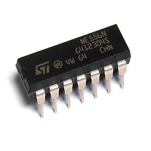
Overview of the 556 Timer IC
The 556 Timer IC is a useful electronic component that combines two 555 timers in one package. This makes it more flexible than a single 555 timer because you can use the two timers separately or together. It can be set up to work as an oscillator, delay timer, pulse generator, or flip-flop. The 556 timer works in two modes: monostable (one-shot) or astable (continuous). It’s used in many electronic projects to create waveforms, time events, or control sequences. The 556 timer can run on voltages between 4.5V and 16V, has adjustable timing settings, can handle high output, and uses little power. Because of these features, it’s a popular choice for you when building reliable and efficient circuits.
556 Timer IC Alternatives
• ICM75561PDZ
• TLC556IN
• NE556N
• 556-1/BCA
• LM556J
• ICM75551PD
• SA556F
• 5962-8950304CA
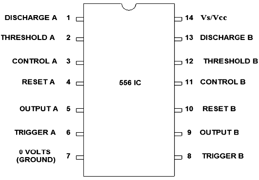
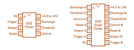
556 Timer IC Pin Configuration
Power, Ground, and Threshold
Pins 1, 3: These connections are designated for the power supply (V+) and ground (V-), along with threshold voltage adjustment. Ensuring these connections’ stability is primary for the circuit’s consistent performance, much like how a stable emotional state fosters clear reasoning. Proper insulation and connection can fend off common issues such as voltage drift and noise interference to shielding oneself from life's distractions.
Timing Intervals
Pins 2, 12: These pins signal the end of timing intervals for tasks needing precise timing control like pulse width modulation and sequential timers. Their role is to setting personal deadlines, maintaining discipline in timing activities.
Voltage Regulation
Pin 14: This pin's task is to regulate the supply voltage (+Ve), ranging from 3 to 15 volts. A stable voltage here is to maintaining a balanced daily routine, preventing erratic behavior in the circuit.
Reset Function
Pins 4, 10: Employed to reset the timing intervals back to their initial states, useful in applications that need periodic resets, such as watchdog timers in microcontrollers. Think of this as hitting the reset button on one's day to start fresh, facilitating productivity.
Grounding
Pin 7: Serving as the main ground connection for the circuit (0 Volts), a solid grounding minimizes electrical noise and maintains the circuit's integrity, similar to how a solid support system can keep someone grounded in trying times.
Pulse Width Management
Pins 3, 11: These manage the pulse width via a voltage divider in dual-timer mode, for fine-tuning output pulse durations, a necessity in signal processing and waveform generation. This is good to fine-tuning one's skills or habits for better efficiency and output.
Timing Activation
Pins 6, 8: They initiate the timing process and their reliability in starting the timing sequence is important for tasks requiring precise start times, like programmable delay circuits. Similar to how initiating a well-timed action can be valuable in achieving personal goals.
Output and Discharging
Pins 1, 13: Act as outputs following the reset signal, enabling periodic capacitor discharge. This function is use in charge/discharge applications seen in analog signal processing, to releasing pent-up energy at the right moment.
Dual Timer Output
Pins 5, 9: Function as output pins for dual timers, making direct interfaces with components needing voltage or current switching. Utilizing these pins enables effective control in applications such as LED dimming and motor control, much like managing resources efficiently in complex projects.
A diligent understanding and proper configuration of these pins can greatly enhance the efficiency of troubleshooting and designing 556 circuits. Different configurations might include single timer mode, dual adjustable pulse generation, or timers with fixed widths. These modes offer wide-ranging functionalities like oscillation, power-saving mechanisms, and precise time-delay generation.
A detailed comprehension of each pin's role in a 556 timer circuit transcends mere connections; it embodies the mastery over defining circuit behavior accurately. By integrating practical design principles and addressing potential issues identified during the development phases, one can fully exploit the capabilities of 556 timers.
Features of 556 Timer Circuits
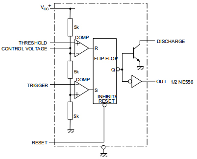
The 556 timer IC integrates two 555 timers, offering intricate control over timing pulses, oscillations, and delays. This range of functionalities makes it a main component across various electronic applications. The features include the following:
Dual Timers
The 556 IC houses two independent 555 circuits named Timer A and Timer B. This integration allows for simultaneous or sequential timing operations within one unit. Such duality extends the circuit's usability in intricate systems demanding multiple timing sequences, aiding complex project requirements.
Wide Voltage Range
Operating within a 4.5V to 15V range, the 556 timer adapts to diverse power requirements. This versatility is a blessing for various applications that depend on different power supplies. In automotive settings, for example, the capacity to function reliably across varied voltage levels ensures compatibility with both low and high power conditions.
High Output Current
With a capacity to drive external loads of up to 200 mA, the 556 timer negates the necessity for additional driver circuits. This attribute proves beneficial in practical scenarios, where reducing the component count leads to more compact, streamlined, and cost-effective designs, enhancing overall efficiency.
Adjustable Timing
Timing parameters such as pulse width, frequency, and delays can be tuned via external resistors and capacitors. This adaptability allows for careful timing customization, which is highly desirable in applications such as signal processing and communication systems, where exact timing control is use for optimal performance.
Trigger and Reset Inputs
The facility to initiate and reset timing cycles through digital or analog signals amplifies the 556 timer's versatility. In automation, for example, the capability to trigger and reset timers based on variable inputs enables dynamic and responsive system operations, easily mirroring the flexibility typical in any situations.
Output Polarity
By offering active-low or active-high output configurations, the 556 timer provides the necessary flexibility to meet the polarity requirements of interfacing circuits. This flexibility is beneficial when integrating with existing systems that have specific input criteria.
Low Power Usage
For energy efficiency, the 556 timer is perfect for battery-powered applications. Its low power consumption makes it ideal for portable devices where energy conservation is great, benefiting a plethora of applications from wearable technology to remote sensing devices.
Temperature Stability
The 556 timer maintains reliable performance across a broad temperature spectrum. This stability is important in environments with temperature variations, ensuring dependable operation in applications ranging from consumer electronics to industrial automation systems.
Flexible Packaging
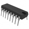
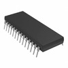
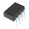
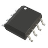
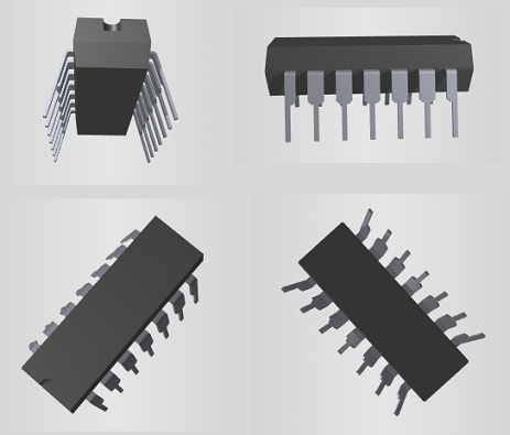
Available in both DIP and SOIC forms, the 556 timer offers versatility in assembly preferences. This flexibility in packaging allows for seamless incorporation into diverse manufacturing processes, making it suitable for both prototype development and mass production. Its dual-timer setup, extensive voltage range, and capacity for high output current, alongside adjustable timing and versatile inputs, render it exceptionally valuable in contemporary electronic design. The IC's efficiency, stability, and flexible packaging options further enhance its practicality across a wide range of scenarios.
NE556 Design
Symbol and Schematic
3D Model and Block Diagram
NE556 Schematic Diagram

556 Block Diagram
Applications of 556 Timer
Pulse Generation
In monostable mode, the NE556 timer produces precise-duration pulses. These pulses synchronize systems, control action durations, and generate timing signals. Environments such as telecommunications greatly benefit, ensuring smooth data transmission with each pulse. Industrial machinery relies on exact pulse generation to maintain operational efficiency and avoid malfunctions.
Oscillator Circuits
When configured in astable mode, the NE556 timer generates stable, periodic square wave outputs. Different digital circuits, alarms, and notification systems rely on these outputs for consistent timing signals. Uses include household appliances like clocks and timers, which depend on the timer for reliable intervals.
Audio Applications
The NE556 timer is use in audio applications. By producing tones, modulating voices, and processing audio signals, it's integrated into devices like synthesizers and communication systems. Public address systems, sirens, and electronic music instruments utilize the timer to generate custom audio signals.
Motor Control
The NE556 timer’s accuracy extends to motor control, enabling precise speed, direction, and timing manipulation in motors. Robotics, automated systems, and industrial machinery benefit from smooth operation during manufacturing. Exact motor control improves product quality and reduces mechanical wear.
Time Delay Circuits
Time delay circuits with the NE556 timer manage actions in response to specific events, debounce switches, and trigger sequential processes. Industrial settings rely on this for machinery and electronic systems to perform operations in a precise sequence. This enhances safety and efficiency in automated production lines.
Flip-Flops and Counters
The NE556 timer can function as flip-flops or binary counters, aiding in memory storage, frequency division, and sequential control. Digital circuits maintain orderly sequences, enhance data storage reliability, and manage frequency accurately in communication systems. Others harness the NE556 to create robust, efficient, and scalable electronic control systems.
Frequently Asked Questions [FAQ]
1. How to use a 556 timer chip?
A 556 timer chip, which integrates two 555 timers, offers versatility in numerous applications. In monostable mode, the output of the first timer is connected to the trigger of the second. The second timer is activated when the first timer's output transitions to a low state. Adjusting the external resistors and capacitors connected to the timers, precise timing intervals can be achieved.
To feel the thrill of creating, consider its use in pulse width modulation (PWM) controllers, and oscillators. For example, in DIY electronics projects, such as creating an LED flasher, and designing a basic time delay circuit. Utilizing the 556 timer can simplify design and execution processes mostly. Furthermore, advanced circuits often use this configuration to generate sequential timing and create multi-stage delay effects.
2. What is a 556 timer IC?
The 556 timer IC is a dual version of the widely renowned 555 timer IC, merging two distinct 555 timer circuits into one package. This integration caters to both dual and independent operations, enhancing functionality. Its compact nature allows for a more efficient use of space on printed circuit boards (PCBs). This feature is greatly appreciated for your electronic design circles.
3. What is the difference between 555 and 556 timer?
Both the 555 and 556 timers serve timing functions, but with a notable difference in their capacity. The 555 is a single timer device. The 556 contains two 555 timers within one package. This allows the 556 timer to perform more intricate timing functions or handle two separate timing tasks concurrently.
4. How much voltage can a 555 timer handle?
A 555 timer accommodates a supply voltage ranging from 4.5V to 15V. However, certain versions are use to withstand up to 18V.
5. What is the maximum speed of 555 timer?
The maximum speed of a 555 timer pertains to its highest operating frequency, which can reach up to around 3 MHz under optimal conditions. In practical applications, the frequencies usually fall within the range of 500 kHz to 2 MHz.
About us
ALLELCO LIMITED
Read more
Quick inquiry
Please send an inquiry, we will respond immediately.
How the ABF025 Sensor Measures Current Efficiently
on October 7th
LM2904 IC Overview Features and Applications
on October 6th
Popular Posts
-

What is GND in the circuit?
on January 1th 2915
-

RJ-45 Connector Guide: RJ-45 Connector Color Codes, Wiring Schemes, R-J45 Applications, RJ-45 Datasheets
on January 1th 2477
-

Fiber Connector Types: SC Vs LC And LC Vs MTP
on January 1th 2064
-

Understanding Power Supply Voltages in Electronics VCC, VDD, VEE, VSS, and GND
on November 8th 1857
-

Comparison Between DB9 and RS232
on January 1th 1749
-

What Is An LR44 Battery?
Electricity, that ubiquitous force, quietly permeates every aspect of our daily lives, from trivial gadgets to life-threatening medical equipment, it plays a silent role. However, truly grasping this energy, especially how to store and efficiently output it, is no easy task. It is against this background that this article will focus on a type of coin cell battery that may seem insignificant on the...on January 1th 1702
-

Understanding the Fundamentals:Inductance Resistance, andCapacitance
In the intricate dance of electrical engineering, a trio of fundamental elements takes center stage: inductance, resistance, and capacitance. Each bears unique traits that dictate the dynamic rhythms of electronic circuits. Here, we embark on a journey to decipher the complexities of these components, to uncover their distinct roles and practical uses within the vast electrical orchestra. Inductan...on January 1th 1647
-

CR2430 Battery Comprehensive Guide: Specifications, Applications and Comparison to CR2032 Batteries
What is CR2430 battery ?Benefits of CR2430 BatteriesNormCR2430 Battery ApplicationsCR2430 EquivalentCR2430 VS CR2032Battery CR2430 SizeWhat to look for when buying the CR2430 and equivalentsData Sheet PDFFrequently Asked Questions Batteries are the heart of small electronic devices. Among the many types available, coin cells play a crucial role, commonly found in calculators, remote controls, and ...on January 1th 1531
-

What Is RF and Why Do We Use It?
Radio Frequency (RF) technology is a key part of modern wireless communication, enabling data transmission over long distances without physical connections. This article delves into the basics of RF, explaining how electromagnetic radiation (EMR) makes RF communication possible. We will explore the principles of EMR, the creation and control of RF signals, and their wide-ranging uses. The article ...on January 1th 1521
-

CR2450 vs CR2032: Can The Battery Be Used Instead?
Lithium manganese batteries do have some similarities with other lithium batteries. High energy density and long service life are the characteristics they have in common. This kind of battery has won the trust and favor of many consumers because of its unique safety. Expensive tech gadgets? Small appliances in our homes? Look around and you'll see them everywhere. Among these many lithium-manganes...on January 1th 1496
