CD4511BE Decoder: How It Works and Where to Use It
A decoder is a digital circuit used to convert encoded data into a format that is easy to understand and use, such as numbers on a display. This article explores the CD4511BE decoder, which converts Binary Coded Decimal (BCD) inputs into outputs that can control a seven-segment display. With its simple design and ability to manage display outputs, the CD4511BE is widely used in devices like digital clocks, calculators, and measurement equipment. The following sections provide detailed information about the CD4511BE’s pin configuration, operating features, practical applications, and frequently asked questions to offer a complete understanding of how this decoder works and where it is commonly applied.Catalog
Understanding the Basics of a Decoder
A decoder is a combinational logic circuit with multiple inputs and outputs. It operates by comparing input data with a preset code and generating the matching decoded outputs. This process converts encoded signals back to their original form, making it simpler to understand and use in various applications.
Decoders are classified into two main types: variable decoders and display decoders. Variable decoders usually have fewer inputs and more outputs, such as n-to-2ⁿ decoders or 8421BCD decoders, which expand input signals into a wider set of outputs. Display decoders, on the other hand, are designed to convert binary numbers into seven-segment codes, commonly used in LED or LCD displays. This makes them ideal for devices like digital clocks or calculators, where numbers need to be shown clearly for easy reading.
Decoders are widely used in systems like microprocessors and memory management, where they help manage memory selection and data flow. By ensuring that encoded signals are accurately converted back to their original form, decoders help maintain smooth operation in digital systems. Display decoders, in particular, demonstrate how binary data can be turned into clear, readable numbers for easy viewing on digital displays.
Comprehensive Guide to the CD4511BE Decoder
The CD4511BE decoder is designed for controlling seven-segment displays with a common cathode setup. It converts Binary Coded Decimal (BCD) inputs into signals that directly drive the segments, making it useful for applications that need clear numeric displays. With features like conversion, blanking, and latch control, it simplifies the process of visual data presentation.
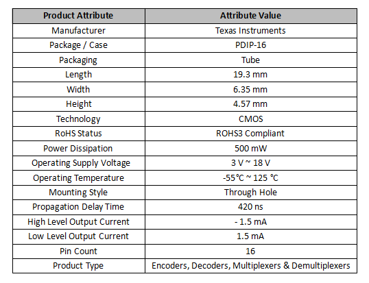
The CD4511BE can operate in temperatures ranging from -55°C to 125°C and supports voltages between 3V and 18V, making it adaptable to various circuits and conditions. It provides enough current to directly drive LED displays without extra driver components, which helps reduce overall circuit complexity. Its robust housing makes it easy to integrate into different electronic systems.
Often found in calculators, instruments, and automotive dashboards, the CD4511BE is reliable for digital displays. The blanking feature allows users to selectively disable segments, which helps in energy-saving scenarios. The latch control ensures stability in the display, even when input data changes, making it dependable for consistent data output.
The CD4511BE’s reliability and flexibility make it suitable for various applications, especially where stable and straightforward numeric displays are needed. Its ability to directly control LED segments simplifies design and improves overall system efficiency.
Alternatives and Equivalents
• CD4511BFMSR
• CD74ACT139E
• HCC4511BF
• MC14511BALD
CD4511BE Decoder: Pin Configuration and Symbol Overview
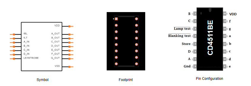
The CD4511BE is widely used in seven-segment display applications. Understanding its pin configuration is essential for effective use. It has a total of 16 pins, each assigned to specific functions that contribute to its overall performance.
Pin 1, 2, 6, 7 (B, C, D, A) – Data Input Pins
These pins serve as the 4-bit Binary Coded Decimal (BCD) inputs, which directly control the segments of the seven-segment display. For example, if the input value is ‘1001’ (9 in decimal), the display will show the number ‘9’. To ensure reliable data input, these pins may be used with debounce mechanisms and pull-down resistors.
Pin 3 (LT) – LED Test Pin
This pin is used for testing purposes. Activating this pin will illuminate all segments of the display, helping to verify that each segment is functioning correctly. It is useful for initial setup and troubleshooting.
Pin 4 (BL) – Blanking Pin
The Blanking (BL) pin can turn off the display without changing the input data. This feature is helpful for power saving or when visually resetting the display. It is often used in applications like digital clocks or counters, where intermittent display blanking might be needed.
Pin 5 (LE) – Latch Enable Pin
The Latch Enable (LE) pin is responsible for storing the BCD input data. When activated, it locks the current input on the display, ensuring stable information output even if the input data changes. This function is useful when consistent display output is required.
Pin 8 (GND) – Ground Pin
This pin serves as the ground reference for the circuit. Proper grounding practices are important for minimizing noise and ensuring stable decoder operation.
Pin 16 (VDD) – Power Supply Pin
The VDD pin is connected to the power supply. A stable voltage here is necessary for the reliable operation of the CD4511BE decoder. It supports a range of 3V to 18V, making it adaptable to various circuit designs.
Pins 9, 10, 11, 12, 13, 14, 15 (e, d, c, b, a, g, f) – Seven-Segment Display Outputs
These pins connect to the seven-segment display and control each segment (labeled a through g). Different combinations of these pins are activated to display numbers from 0 to 9. For example, segments ‘a, b, c, e, f, g’ light up to show the number ‘0’. Ensuring consistent voltage levels across these pins prevents segment dimming or ghosting effects on the display.
Detailed Specifications of the CD4511BE Decoder
Key Features and Characteristics of the CD4511BE Decoder
The CD4511BE decoder is built with features that make it effective for a wide range of decoding tasks.
CMOS Technology and Noise Immunity
The CD4511BE uses CMOS technology, which provides low power consumption and strong resistance to electrical noise. This means it can work efficiently in different electronic environments without drawing much power or being affected by electrical interference. This characteristic makes it suitable for systems that need to manage power efficiently while maintaining stable performance.
Efficient Logic Circuitry
The CD4511BE has an efficient logic design that helps reduce overall power usage while ensuring stable operation. Its internal structure is built to optimize power management, which is beneficial for extending battery life in portable devices and lowering energy costs in larger systems.
Input Latch Functionality
The input latch feature of the CD4511BE allows it to store Binary-Coded Decimal (BCD) data, keeping the output stable even if the input changes. This is useful in devices like digital clocks, where consistent outputs are needed for accurate timekeeping, regardless of input fluctuations.
Programmable BCD Input and Blanking Controls
The CD4511BE has programmable BCD input and blanking controls, offering more options for controlling display outputs. This flexibility makes it adaptable for various digital display applications, where controlling the display state dynamically is required.
High Output Drive Capability
With an output drive capability of up to 25mA, the CD4511BE can directly control common anode or cathode LED displays without needing extra driver circuits. This simplifies the circuit design and reduces the number of additional components, allowing for a more compact and cost-effective setup.
How the CD4511BE Decoder Works: Functional Mechanism Explained
The CD4511BE decoder operates through several connected processes that ensure accurate number representation on a 7-segment display.
BCD Input
The decoder has four input pins labeled A, B, C, and D that receive Binary-Coded Decimal (BCD) codes. These pins determine which number will be displayed. For the display to work correctly, the input signals need to be stable and free from noise. This means the signals should be filtered and not include any bouncing effects, which helps improve display reliability and ensures accurate outputs.
Latch Mechanism
The CD4511BE has a latch mechanism that activates when the Latch Enable (LE) pin is set high. Once the input data is latched, it holds the display's current output, regardless of changes in the input. This function is useful for applications where a stable display is needed, similar to holding a single frame steady in a video so that the displayed image doesn’t flicker.
Decoding Process
After the input data is latched, it undergoes a decoding process. The decoder takes the 4-bit binary input and determines which of the segments (a to g) on the 7-segment display should light up. This process converts the BCD input into a format that can be visually understood, showing numbers based on the binary input provided.
Segment Control and Display Output
The decoder controls the segments of the 7-segment display through its output pins (a to g). Each pin controls a specific segment, and whether a segment lights up depends on the state of its corresponding pin. This control allows for the creation of different numerical patterns, enabling the display to show numbers clearly.
Blanking Feature
When the input code is "1111" and the blanking input is set low, all segments of the display turn off. This feature is useful for temporarily hiding the contents on the display without altering the input data. It’s often used in digital clocks or timing devices to clear the display at certain times.
Latch Clearing Mechanism
The latch can be cleared by setting the LE pin to a low state, which resets the display output. This mechanism allows for periodic resets of the display, ensuring that the data shown is always accurate. This feature is especially helpful in systems that need to update display content frequently, maintaining clear and consistent information.
Practical Implications and Advanced Observations
Understanding the CD4511BE’s input conditioning, latching function, and decoding process is crucial for accurate implementation. Properly managing these mechanisms ensures that the display shows precise information, making the decoder a dependable choice for various electronic applications where stable and clear numerical displays are needed.
CD4511BE Decoder Circuit Design Example
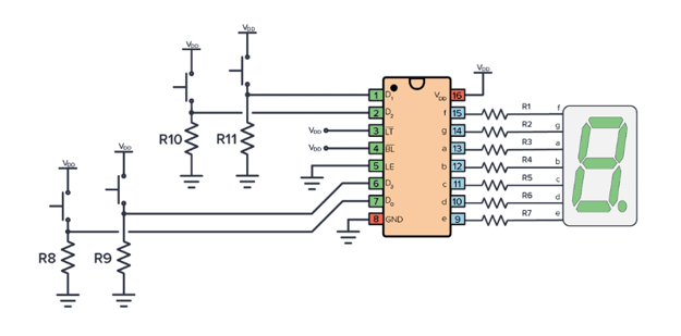
Best Practices for Using the CD4511BE Decoder Effectively
To use the CD4511BE decoder correctly, start by connecting the GND pin to the negative terminal of the power supply and the VDD pin to the positive terminal. This step ensures a stable power connection, which is necessary for proper circuit operation. Setting up the power supply correctly provides a grounded reference and the required voltage for the decoder to function.
Next, connect the binary inputs to pins B, C, D, and A, as these are used to receive binary codes that the decoder will convert into a displayable format. Make sure that the input follows the binary counting sequence to ensure accurate display outputs. After configuring the inputs, link the output pins to the seven-segment display. This connection will translate the binary inputs into a readable numerical format, which is widely used in digital displays and diagnostic tools.
The Lamp Test (LT) pin can be used to check the display functionality. Setting this pin high will light up all the segments on the display, making it easy to verify if every segment is working as expected. This feature is especially useful during setup or maintenance.
The Latch Enable (LE) pin helps store the current display value. Keep this pin in a low state for continuous operation, which stabilizes the display output. This allows the display to reflect changes in input data only when necessary, ensuring consistent and steady performance.
The CD4511BE decoder is widely used in devices like digital clocks, calculators, and instrumentation displays. Correctly setting up the power, inputs, and outputs, along with using the LT and LE pins effectively, can improve the performance and accuracy of these devices, making the CD4511BE a dependable option for various applications.
Real-World Applications of the CD4511BE Decoder
The CD4511BE is widely known for its ability to convert binary inputs into a seven-segment display format, making it useful in various applications.
Counters
The CD4511BE is commonly used in counters, where it converts binary data into a readable decimal format for numerical display systems. It is often found in digital timers and event counters in industrial machinery, providing accurate real-time data and improving user interaction by presenting clear information on digital displays.
Temperature Controllers
In temperature controllers, the CD4511BE helps display precise temperature readings. It decodes binary signals from temperature sensors into decimal outputs, making it easy to monitor and control thermal conditions. This is useful in both consumer appliances and industrial systems, where maintaining specific temperature levels is necessary for safe and efficient operation.
Digital Instruments
Digital instruments often use the CD4511BE to convert binary inputs into clear and understandable readings. This makes it ideal for measuring voltage, current, and resistance in various settings like laboratories, repair shops, and quality control processes in manufacturing.
LED Lighting Systems
The CD4511BE is also used in advanced LED lighting systems to control multi-segment displays. It helps show lighting levels and modes accurately, supporting smart lighting solutions that allow for user customization and real-time feedback, creating the desired lighting environment.
Digital Clocks
Digital clocks use the CD4511BE to present time data clearly and precisely. The decoder converts binary time information into a human-readable format, ensuring reliable time display in devices ranging from personal electronics to public clocks.
Measurement Equipment
The CD4511BE is beneficial in measurement equipment, where it decodes and presents readings from various sensors. This capability is especially useful in areas like environmental monitoring, where displaying data on factors like air quality or humidity needs to be accurate and easy to understand for proper analysis and decision-making.
Smart Home Devices
In smart home devices, the CD4511BE plays a role in visual feedback systems by displaying the status of home automation systems and showing real-time data like energy consumption. This enhances the user experience and makes interacting with smart home networks simpler and more intuitive.
The CD4511BE’s versatility and ability to display clear, readable information make it a suitable choice for a wide range of modern digital systems, contributing to a better user experience and more efficient operation.
Frequently Asked Questions [FAQ]
1. How is BCD converted to a segment display?
The BCD (Binary-Coded Decimal) number is converted for use in a seven-segment display through a decoding process. This process translates the binary values into signals that light up specific segments on the display to form numbers. This translation helps create a clear and readable visual representation of the digital data.
2. What is the primary use of CD4511BE?
The CD4511BE is used to convert BCD inputs into a seven-segment display format. It takes binary data as input and sends signals to light up the appropriate segments on the display. This makes it easier to visualize numerical data, which is useful in digital systems where showing numbers clearly is needed.
3. What is the operational temperature range for the CD4511BE?
The CD4511BE operates within a temperature range of -55°C to 125°C. This wide range allows it to function reliably in different environmental conditions, making it suitable for applications that may be exposed to both low and high temperatures.
4. How is CD4511BE applied in circuits?
The CD4511BE is often used with microcontrollers and counters in circuits that require numerical displays. It is commonly found in digital clocks, temperature displays, and other devices that need accurate number representation. For example, in a temperature display system, the CD4511BE decodes binary data from a sensor and converts it into a numerical format for the seven-segment display, making it easy to read.
5. What is the role of a seven-segment display?
A seven-segment display shows numerical information using LEDs arranged in a specific pattern. Each segment can be turned on or off individually to form numbers from zero to nine. This arrangement helps simplify data representation and improves readability in consumer electronics and other devices, making complex data easier to understand visually.
About us
ALLELCO LIMITED
Read more
Quick inquiry
Please send an inquiry, we will respond immediately.
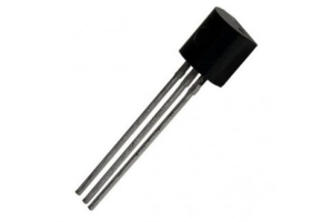
2N5486 Transistor: Pin Configuration and Common Applications
on September 28th
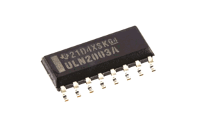
ULN2003AD Alternatives, Circuit Design, Functionality, and Layout
on September 27th
Popular Posts
-

What is GND in the circuit?
on January 1th 3105
-

RJ-45 Connector Guide: RJ-45 Connector Color Codes, Wiring Schemes, R-J45 Applications, RJ-45 Datasheets
on January 1th 2671
-

Understanding Power Supply Voltages in Electronics VCC, VDD, VEE, VSS, and GND
on November 15th 2209
-

Fiber Connector Types: SC Vs LC And LC Vs MTP
on January 1th 2182
-

Comparison Between DB9 and RS232
on January 1th 1802
-

What Is An LR44 Battery?
Electricity, that ubiquitous force, quietly permeates every aspect of our daily lives, from trivial gadgets to life-threatening medical equipment, it plays a silent role. However, truly grasping this energy, especially how to store and efficiently output it, is no easy task. It is against this background that this article will focus on a type of coin cell battery that may seem insignificant on the...on January 1th 1774
-

Understanding the Fundamentals:Inductance Resistance, andCapacitance
In the intricate dance of electrical engineering, a trio of fundamental elements takes center stage: inductance, resistance, and capacitance. Each bears unique traits that dictate the dynamic rhythms of electronic circuits. Here, we embark on a journey to decipher the complexities of these components, to uncover their distinct roles and practical uses within the vast electrical orchestra. Inductan...on January 1th 1728
-

CR2430 Battery Comprehensive Guide: Specifications, Applications and Comparison to CR2032 Batteries
What is CR2430 battery ?Benefits of CR2430 BatteriesNormCR2430 Battery ApplicationsCR2430 EquivalentCR2430 VS CR2032Battery CR2430 SizeWhat to look for when buying the CR2430 and equivalentsData Sheet PDFFrequently Asked Questions Batteries are the heart of small electronic devices. Among the many types available, coin cells play a crucial role, commonly found in calculators, remote controls, and ...on January 1th 1673
-

What Is RF and Why Do We Use It?
Radio Frequency (RF) technology is a key part of modern wireless communication, enabling data transmission over long distances without physical connections. This article delves into the basics of RF, explaining how electromagnetic radiation (EMR) makes RF communication possible. We will explore the principles of EMR, the creation and control of RF signals, and their wide-ranging uses. The article ...on January 1th 1670
-

Comprehensive guide to hFE in transistors
Transistors are crucial components in modern electronic devices, enabling signal amplification and control. This article delves into the knowledge surrounding hFE, including how to select a transistor's hFE value, how to find hFE, and the gain of different types of transistors. Through our exploration of hFE, we gain a deeper understanding of how transistors work and their role in electronic circu...on November 15th 1631
HOT Part Number
-

THS4081CDGNR
Texas Instruments
IC OPAMP VFB 1 CIRCUIT 8HVSSOP
TL3780AF330QG
E-Switch
SWITCH TACTILE SPST-NO 0.02A 15V
C0603X7R1H331M
TDK Corporation
CAP CER 330PF 50V X7R 0201
DDZ17-7
Diodes Incorporated
DIODE ZENER 17V 500MW SOD123
2225WC822KAT1A
KYOCERA AVX
CAP CER 8200PF 2.5KV X7R 2225
24AA024T-I/MNY
Microchip Technology
IC EEPROM 2KBIT I2C 400KHZ 8TDFN
STM32H743IGT6
STMicroelectronics
IC MCU 32BIT 1MB FLASH 176LQFP
MCP112T-270E/TT
Microchip Technology
IC SUPERVISOR 1 CHANNEL SOT23-3
TLZ18B-GS08
Vishay General Semiconductor - Diodes Division
DIODE ZENER 18V 500MW SOD80
LX8117A-05CDT
Microsemi Corporation
IC REG LINEAR 5V 1A TO252
SN54LS151J
Texas Instruments
54LS151 DATA SELECTORS/MULTIPLEX
BFL4036
Sanyo
MOSFET N-CH 500V 9.6A TO220F-3FS
STN1N20
STMicroelectronics
MOSFET N-CH 200V 1A SOT223
ATMEGA649-16MU
Microchip Technology
IC MCU 8BIT 64KB FLASH 64QFN
TPS7B8550QWDRCRQ1
Texas Instruments
AUTOMOTIVE 150-MA, 40-V, LOW-DRO
SN75ALS176AD
Texas Instruments
IC TRANSCEIVER HALF 1/1 8SOIC
TXS0108ENMER
Texas Instruments
IC TRANSLATOR BIDIR 20NFBGA
BLM18BB121SN1D
Murata Electronics
FERRITE BEAD 120 OHM 0603 1LN -

0603YC561KAT2A
KYOCERA AVX
CAP CER 560PF 16V X7R 0603
12065A911JAT2A
KYOCERA AVX
CAP CER 910PF 50V NP0 1206
OPA2210IDRGT
Texas Instruments
IC OPAMP GP 2 CIRCUIT 8SON
RC0402FR-07301KL
Yageo
RES SMD 301K OHM 1% 1/16W 0402
VT261WFQX-ADJ
Analog Devices Inc./Maxim Integrated
IC CHIP ADJ QFN SMD
SN74LVC74AD
Texas Instruments
IC FF D-TYPE DUAL 1BIT 14SOIC
ADUM1201WURZ-RL7
Analog Devices Inc.
DGTL ISO 2500VRMS 2CH GP 8SOIC
AR1021T-I/ML
Microchip Technology
IC SCREEN CNTRL 10BIT 20QFN
TS5N412PW
Texas Instruments
IC SWITCH SPDTX4 12.5OHM 16TSSOP
NTE5989
NTE Electronics, Inc
DIODE GEN PURP 300V 40A DO5
FAN6248HCMX
onsemi
LLC SR CONTROLLER
HCPL-0302-000E
Broadcom Limited
OPTOISO 3.75KV 1CH GATE DRVR 8SO
1206YC123MAT2A
KYOCERA AVX
CAP CER 0.012UF 16V X7R 1206
782763820
Würth Elektronik
FERRITE BEAD 82 OHM 1206 1LN
GCM0335C1ER30BD03D
Murata Electronics
CAP CER 0.3PF 25V C0G/NP0 0201
DMP2225LQ-7
Diodes Incorporated
MOSFET BVDSS: 8V~24V SOT23 T&R 3
EPM7064BTC44-3N
Intel
IC CPLD 64MC 3.5NS 44TQFP
MSP430G2453IPW20
Texas Instruments
IC MCU 16BIT 8KB FLASH 20TSSOP -
2N4912
NTE Electronics, Inc
TRANS PNP 80V 4A TO66
GQM2195C2E5R6BB12D
Murata Electronics
CAP CER 5.6PF 250V NP0 0805
MAX1316ECM+T
Analog Devices Inc./Maxim Integrated
IC ADC 14BIT SAR 48LQFP
TC1015-3.3VCT713
Microchip Technology
IC REG LINEAR 3.3V 100MA SOT23-5
ISL6115CBZA-T
Renesas Electronics America Inc
IC HOT SWAP CTRLR GP 8SOIC
SY100EL56VZC
Microchip Technology
IC DIFF DIG MULTPL 2X2:1 20SOIC
SN74ABT16541ADGGR
Texas Instruments
IC BUF NON-INVERT 5.5V 48TSSOP
CY8C4014PVI-412
Infineon Technologies
IC MCU 32BIT 16KB FLASH 28SSOP
RT0805DRE071KL
Yageo
RES SMD 1K OHM 0.5% 1/8W 0805
CY15B104QSN-108SXI
Infineon Technologies
IC FRAM 4MBIT SPI/QUAD 8SOIC
XC2V4000-4FFG1152I
AMD
IC FPGA 824 I/O 1152FCBGA
LDK320M33R
STMicroelectronics
IC REG LINEAR 3.3V 200MA SOT23-5
MC14001UBDR2G
onsemi
IC GATE NOR 4CH 2-INP 14SOIC
08052A470JAT2A
KYOCERA AVX
CAP CER 47PF 200V C0G/NP0 0805
MAX560CAI+T
Analog Devices Inc./Maxim Integrated
IC TRANSCEIVER FULL 4/5 28SSOP
SRP1245A-4R7M
Bourns Inc.
FIXED IND 4.7UH 12A 15 MOHM SMD
MMSZ5235B-E3-08
Vishay General Semiconductor - Diodes Division
DIODE ZENER 6.8V 500MW SOD123
06033C682KAT2A
KYOCERA AVX
CAP CER 6800PF 25V X7R 0603