ULN2003AD Alternatives, Circuit Design, Functionality, and Layout
The ULN2003AD is a versatile and powerful Darlington transistor array, widely recognized for its ability to manage high voltage and current in a variety of applications. This introduction explores the key features of the ULN2003AD, such as its seven NPN Darlington pairs and integrated clamping diodes, which make it ideal for controlling inductive loads like motors, relays, and lamps. With each pair capable of handling 500mA, it has proven its reliability in sectors ranging from automotive to industrial automation. As we delve deeper, we’ll uncover how this component enhances performance across multiple use cases and what considerations are required for its optimal integration into your designs.Catalog
In-Depth Analysis of ULN2003AD
ULN2003AD, a versatile Darlington transistor array, is designed for applications requiring proficient high voltage and current management. It boasts seven NPN Darlington pairs, offering formidable high voltage outputs, and integrates common cathode clamping diodes tailored for controlling inductive loads.
Each transistor pair can handle a collector current of 500mA, with potential for increased capacity through parallel configurations. Incorporated within each Darlington transistor is a 2.7Kohm series base resistor, facilitating direct connectivity to TTL or 5V CMOS devices. This array excels in numerous applications such as lamp drivers, relay drivers, display drivers, hammer drivers, logic buffers, and line drivers.
Replacements and Equivalents
ULN2003AD Symbol, Footprint, and Pin Configuration
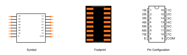
The ULN2003AD features a 16-pin dual in-line package, organized into two rows with eight pins each. Connections of particular interest include seven output pins (OUT1-OUT7), a central input pin (IN), a ground pin (GND), and seven power supply pins (VCC1-VCC7).
Symbol
The symbol of the ULN2003AD delineates its active connections and functions. Each output pin (OUT1-OUT7) links to a corresponding input pin, signifying the device's capacity to interface with low-level signals and manage high-power loads. Suggestively, one input pin can connect to multiple output pins, emphasizing its adaptability in various scenarios.
Footprint
Designing the footprint of the ULN2003AD demands attention to detail to ensure a seamless fit into the circuit layout. Proper PCB designs typically allocate enough spacing for thermal dissipation, promoting stable operations. It is often wise to leave a small margin around the IC to accommodate potential temperature increases and minimize interference with neighboring components.
Pin Configuration
• Output Pins (OUT1-OUT7): These seven output pins drive diverse loads, from LEDs to relays. The outputs are primarily Darlington pairs, amplifying current gain considerably, making the ULN2003AD apt for applications necessitating high current from low current inputs.
• Input Pin (IN): Serving as the control hub for the output pins, the input pin's versatility allows seamless interfacing with various microcontrollers and logic circuits. Ensuring compatibility with voltage levels and current requirements of control logic is used for smooth integration, bridging the gap between low-power control and high-power operations.
• Ground Pin (GND): The ground pin sets an initial reference point for the IC's proper functionality. Employing effective grounding practices, such as using a common ground plane, fosters a stable environment, reduces noise, and ensures reliable operations. A low resistance path to the ground becomes exceptionally pertinent in high-frequency applications to mitigate signal integrity issues.
• Power Supply Pins (VCC1-VCC7): The power supply pins provide the required current to the outputs while avoiding weighty voltage drops. They ensure operation within the specified voltage range, thus preserving consistent performance.
ULN2003AD Features
The ULN2003AD, a meticulously crafted device, caters to 14V to 25V PMOS needs. Its design extends compatibility to both TTL and CMOS levels, facilitating effortless integration with myriad digital circuits. Such flexibility is mostly advantageous when interfacing with various microcontroller systems and digital logic. Capable of handling currents from 500mA to 600mA, the ULN2003AD is an excellent choice for medium-power applications.
Built-in Protections
One of the standout features of the ULN2003AD is its robust protection mechanisms. It incorporates over-current protection to prevent damage from short circuits or overloads, ensuring the device's reliability and longevity even under adverse conditions. Over-temperature protection safeguards the device during prolonged high-power operation, preserving its thermal and electrical stability—a major aspect learned through hands-on circuit design experiences, where mitigating hardware failures often proves dynamic.
Input Regulation
Each input of the ULN2003AD is equipped with a series Zener diode and a resistor. This combination plays a major role in regulating the input current and protecting connected circuits from potential spikes or irregularities. The Zener diode acts as a fixed voltage reference, while the resistor limits current flow, reflecting a design choice that enhances stability and protection, frequently observed in professional circuit designs.
Reverse Voltage Protection
The device integrates reverse voltage protection for its output ports. This feature is advantageous in scenarios where incorrect wiring could lead to component damage, ensuring that accidental reverse polarity does not compromise overall system integrity. Integrating reverse protection components has continually proven to strengthen system robustness, pointedly reducing the risk of reverse polarity errors—common during initial circuit testing and prototyping stages.
Technical Specifications of ULN2003AD
|
Product Attribute |
Attribute Value |
|
Manufacturer |
Texas Instruments |
|
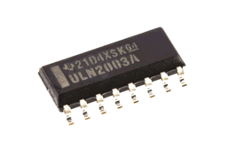
Package / Case |
SOIC-Narrow-16 |
|
Packaging |
Tube |
|
Length |
9.9 mm |
|
Width |
3.91 mm |
|
Height |
1.58 mm |
|
Part Status |
Active |
|
Transistor Polarity |
NPN |
|
Operating Temperature |
-20°C ~ 70°C |
|
Configuration |
Array 7 |
|
Mounting Style |
SMD/SMT |
|
Pin Count |
16 |
|
Product Category |
Darlington Transistors |
Operation of ULN2003AD
The operational dynamics of the ULN2003AD are deeply rooted in the switching behavior of its Darlington pairs, which are activated by the provided input signal. When this input signal registers as high, the Darlington pair is rendered inactive, leading to a decreased output. Conversely, a low input signal triggers the activation of the Darlington pair, culminating in a heightened output. To manage input currents, each base incorporates Zener diodes and resistors.
Darlington Pair Configuration
An ultimate aspect of the ULN2003AD is its Darlington pair structure. This arrangement involves two bipolar transistors configured such that the initial transistor's amplified current is further intensified by the second one. This configuration suggestively boosts current gain, rendering the device exceptionally capable of driving loads that necessitate substantial current with minimal input.
Input Signal Processing
The ULN2003AD processes input signals using a synergy of resistors and Zener diodes associated with each base. Resistors are employed to limit the base current of the transistors, ensuring optimal function without breaching thermal constraints. Zener diodes establish a stable reference voltage, shielding transistors from voltage spikes that could potentially harm the circuitry. This design choice not only stabilizes the input but also augments the device's reliability and lifespan.
ULN2003AD Layout Guidelines
Input and Output Trace Widths
To achieve the best performance with the ULN2003AD Darlington transistor array, the widths of input and output traces must be carefully designed according to the current they will carry. Input traces should be thin as they handle low-current logic signals. Output traces, on the other hand, need to be suggestively thicker to manage higher currents typically associated with ULN2003AD outputs. Choosing the right trace widths influences how the circuit operates thin output traces can cause excessive heat, potentially lowering the circuit's reliability and efficiency. Thick input traces might unnecessarily consume board space without offering added benefits.
Minimizing Crosstalk
Adequate separation between input channels is basic to minimize crosstalk. Crosstalk introduces noise and unwanted signal interference, affecting logic operations. Suitable spacing of input traces reduces such interference. Practical measures include arranging input traces in non-parallel paths and applying grounding techniques to effectively isolate channels.
Common Emitter Trace Considerations
The width of the common emitter trace is authoritative for managing total return currents. This trace should be wide enough to handle up to 2.5A of collective current. Insufficiently sized common emitter traces may cause voltage drops or excessive heating, impacting circuit performance. Using a copper pour or a wider trace for the common emitter is advantageous, providing a low-resistance pathway for return currents. Thoughtful layout design enhances the reliability and performance of the ULN2003AD.
Uses of ULN2003AD
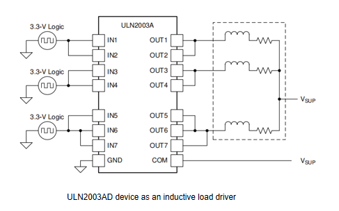
The ULN2003AD provides a capable solution for controlling high-voltage and high-current peripherals from microcontrollers (MCUs) or logic devices. It has a wide range of practical applications, including motors, solenoids, and relays, making it adept at efficiently driving inductive loads.
Motor Control
The ULN2003AD is commonly used in motor control due to its proficiency in managing multiple DC motors with ease. Integrated Darlington transistor arrays handle the load current needs of stepper and DC motors in robots, automation systems, and manufacturing equipment. For example, in robotic systems, effective motor control ensures precise movements. The ULN2003AD supports this by delivering stable current flow. It also offers protection against back EMF (Electromotive Force).
Solenoid Operation
Solenoids, which convert electrical energy into mechanical movement, see substantial benefits from the ULN2003AD. It is requisite in door locking mechanisms, automated valves, and mechanical actuators. The ULN2003AD provides consistent voltage and rapid activation without damage from overcurrent, making it a staple in home automation and industrial controls.
Relay Driving
Relays, basic for controlling high-power devices via low-power signals, match well with the ULN2003AD. Its integrated flyback diodes protect against voltage spikes, securing the relay from potential damage. This is dangerous in automotive electronics, and HVAC systems. The consistent operation of relays ensures system reliability and longevity.
Enhancing Applications with the ULN2003AD
Connecting to Power Supply
To commence, securely attach the power supply to the Vcc and COM pins of the ULN2003AD. This establishes a steadfast power source for the device. A stable connection mitigates the threat of intermittent power issues, which may lead to unpredictable behavior in connected components during practical use.
Integrating Input Signals
Proceed by interfacing input signals from digital devices to the IN1 through IN7 pins. These signals can originate from microcontrollers, logic circuits, or other digital systems. Employing robust debugging practices and oscilloscope measurements validates signal integrity, ensuring dependable switching operations in actual scenarios.
Load Connections to Output Pins
Attach loads to the corresponding output pins (OUT1-OUT7). Each output pin matches its respective input pin: OUT1 to IN1, OUT2 to IN2, and so on. In practical circuits, careful selection of loads in compliance with the ULN2003AD’s electrical characteristics is active for optimal performance and reliability.
Establishing Ground Connections
Make sure that all load ground connections are securely wired to the COM pin. This common ground setup minimizes potential differences across the circuit, aiding in preventing malfunctions. Ground loops, often a substantial noise source in engineering practice, should be meticulously avoided.
Controlling Outputs via Inputs
Control each output by toggling its corresponding input pin. The ULN2003AD’s internal circuitry converts these input signals into desired output states. Utilizing software control mechanisms like pulse-width modulation (PWM) can yield precise and efficient control over the output loads.
Leveraging Built-in Protection Features
Understanding the ULN2003AD's protection features is dynamic to prevent overcurrent damage. These mechanisms shield both the IC and connected loads from operational limit breaches, enhancing overall system longevity and reliability. Experienced engineers typically conduct thorough initial testing to ensure these features activate correctly under abnormal conditions.
Frequently Asked Questions
1. What is the use of ULN2003?
ULN2003 is often found in circuits responsible for driving relays, solenoids, LED displays, and stepper motors. By acting as a driver, it utilizes its Darlington transistor array to magnify weak signals, enabling the control of larger loads.
2. What is the ULN2003 driver?
The ULN2003 driver board includes seven Darlington pairs. Each pair can drive loads up to 500mA and 50V, making it suitable for a broad range of motor and relay driver applications. Its wide applicability extends to automated systems and industrial machinery where dependable load control is active.
3. What is the replacement and equivalent of ULN2003AD?
Equivalents for the ULN2003AD include ULN2003ADR, ULN2003ADR2G, ULN2004ADR, and ULN2004AD. These alternatives provide similar features and performance, maintaining the consistency desired in applications originally using the ULN2003AD.
4. What is the purpose of the ULN2003AD?
The ULN2003AD serves to bridge low-level digital outputs with high-power loads such as relays and motors. It amplifies current, enabling low-power signals to manage high-power devices. This ensures the protection of sensitive components and the integrity of the overall system.
5. What are some typical applications of the ULN2003AD?
Commonly, the ULN2003AD is used in driving relays, operating stepper motors, controlling high-power LEDs, and managing solenoids. In addition, it finds applications in various automation projects. For example, it enhances the accuracy and efficiency of robotic movements and complex lighting systems, showcasing its practical benefits and roles in actual scenarios.