Up/Down Counters with Circuit Examples and the 74193 IC
This article explores up/down counters, basic for managing dynamic numerical values in digital electronics. It starts with their basic functions, covering 4-bit and 3-bit configurations and their bidirectional counting capabilities. The focus then shifts to their circuit designs and the importance of clock pulses for precision and reliability. Lastly, the article highlights their extensive applications in various industrial and technological systems, demonstrating their importance in everything from mechanical controls to digital electronics.Catalog
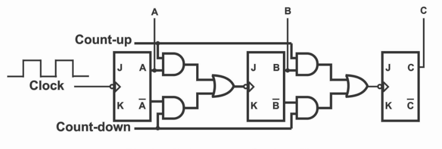
Figure 1: Up/Down Counter
Breakdown of the Up/Down Counter
An Up/Down Counter, or bidirectional counter, monitors and adjusts numerical values in both upward and downward directions based on an input signal. This dual functionality is basic in systems that require increasing and decreasing counts, responding dynamically to changes in the operational environment. These counters typically start at zero and increment until they reach a predetermined limit, which triggers an action in the system. Alternatively, they may begin at a set maximum value and decrease down to zero, activating a similar response upon reaching the lower bound.
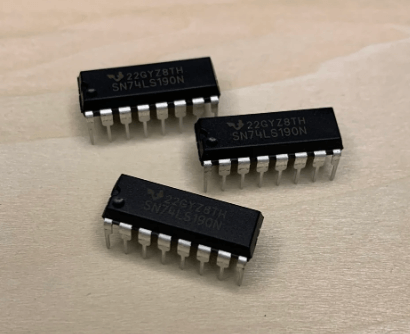
Figure 2: TTL 74LS190 Models
For example, the TTL 74LS190 and 74LS191 models are common versions of this counter. They feature a mode input pin that allows switching between upward and downward counting. This mode switch happens smoothly, without interrupting the counting sequence.
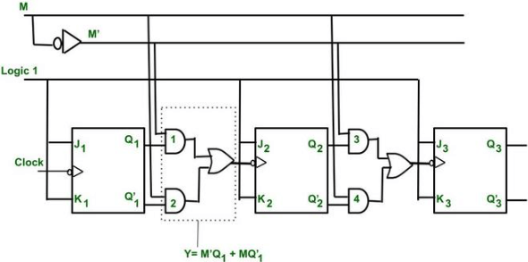
Figure 3: 4-bit Up/Down Counter
A typical 4-bit up/down counter clearly illustrates this operational flexibility. When configured to count upward, the counter moves from the binary value 0000 to 1111, covering all possible combinations within a 4-bit system (0 to 15 in decimal). Switching to count downward reverses this process, decrementing back to 0000. The change between each number happens with precision, controlled by a clock signal that drives the counting in sync with the system’s timing requirements.
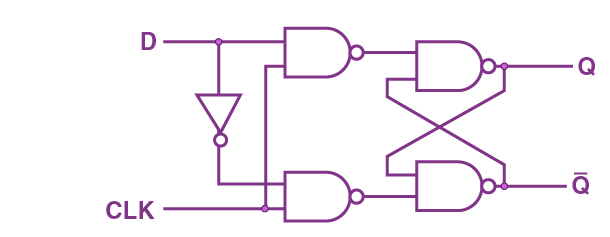
Figure 4: D-type flip-flop
Each of the four bits is controlled by a D-type flip-flop in an edge-triggered setup. These flip-flops work together in a chain, with the output of each flip-flop feeding into the next. To ensure accurate counting, the counter uses the inverted output from each flip-flop as feedback to its data input, especially during the downward count. This design creates a smooth, predictable transition between numbers. Each flip-flop's state change directly influences the next, which keeps the counting process reliable and in sequence.
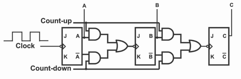
Figure 5: 3-bit Up/Down Counter
Building an Up/Down Counter Circuit
The circuit design for a 3-bit up/down counter uses an efficient setup where JK flip-flops are reconfigured as T-type (toggle) flip-flops. This modification allows the counter to toggle smoothly between counting up from 0 (binary 000) to 7 (binary 111) and counting down in reverse. The simplicity of this design enhances its functionality and reliability.
In the up-counting mode, the sequence is controlled by the output from each flip-flop. Specifically, the 'Q' output of one flip-flop is connected directly to the clock input of the next flip-flop. This setup ensures that each flip-flop toggles in response to the one before it. As the clock pulses are received, the counter increments one step at a time, starting from 000 and moving sequentially up to 111. This direct linkage between flip-flops ensures a smooth and logical progression during the up-counting phase, with each flip-flop's state change driving the next one in line.
When the counter is set to count down, the mechanism reverses. Instead of using the direct 'Q' outputs, the system relies on the inverted outputs of each flip-flop. These inverted signals feed into the clock inputs of the following flip-flops, causing the counter to step down in a controlled, sequential manner. Each clock pulse now triggers a decrement in the binary sequence, from 111 back down to 000. This method ensures that the transitions remain orderly, avoiding any disruptions in the counting process.
How an Up/Down Counter Functions?
The operation of an up/down counter is controlled by an up/down input signal, which directly sets the counting direction. This input ensures that the counter either counts up or down, but never both at the same time. The system achieves this exclusivity by using an inverter, which flips the control signal, making sure that only one counting mode is active at any given moment.
Up Counting Mode: When the counter is set to count up, a specific set of logic gates is activated. These gates guide the counter through a step-by-step progression, starting at binary 000 and moving up to 111 (or from 0 to 7 in decimal). Each clock pulse triggers a jump to the next binary number, maintaining a smooth and predictable sequence. The design ensures that the counter follows a clear and consistent pattern, adhering to standard binary progression rules.
Down Counting Mode: Switching the counter to count down causes the circuitry to adapt in a controlled way. The logic gates that manage the upward count are now turned off, while another set of gates takes over to handle the downward counting process. In this mode, the system relies on inverted signals that flow through the flip-flops, which are responsible for controlling the countdown. As clock pulses continue, the counter steps backward from 111 to 000, just as smoothly and reliably as it counts upward. This change in operation shows the counter’s ability to handle both directions efficiently.
Counting Clock Pulses with an Up/Down Counter
The way up/down counters interact with clock pulses provides valuable insight into their ability to manage timing and sequence control. In an asynchronous counter, each clock pulse directly influences the states of the counter’s flip-flops, driving the counting process.
Down Counting Process with Clock Pulses
In a typical down-counting mode, the counter might start at a binary value of 111 (which equals 7 in decimal). The system reacts to the negative edge of each clock pulse, causing the output of the first flip-flop (QA) to change. This change then triggers a cascading effect, where the output of QA affects the next flip-flop (QB), and eventually influences the third flip-flop (QC). As each clock pulse arrives, this cascade continues, reducing the count step-by-step from 7 down to 0. Each flip-flop is influenced in sequence by the previous one, ensuring that the counting progresses smoothly and predictably.
Up-Counting Process with Clock Pulses
During up-counting, the process is slightly different. Here, the output of each flip-flop triggers the next flip-flop in line. Starting from 000 (binary 0), each clock pulse increments the counter, with the first flip-flop triggering the second, and the second triggering the third. This process continues until the counter reaches 111 (binary 7). Every eighth clock pulse completes the counting cycle, at which point the counter resets back to 000 and begins again. This ensures a consistent and repetitive cycle that maintains precise timing.
Exploring the IC 74193 Up/Down Counter
The 74193 IC is a versatile 4-bit synchronous up/down binary counter capable of counting in both directions, up to modulo-16. It uses dual clock inputs—one for counting up and one for counting down—allowing precise control over the counting direction. This design ensures that the counter’s output stays in perfect sync with the input clock signals, improving both accuracy and responsiveness in its operations.
A key feature of the 74193 IC is its master reset pin. This pin instantly clears the current count, setting all outputs to zero. It’s particularly useful during system testing or when you need to restart the counter at a known state. This makes reconfiguring or troubleshooting systems faster and more efficient. In addition, the IC has dedicated count-up and count-down terminals, which further enhance its flexibility, making it suitable for various digital counting applications where precise control is needed.
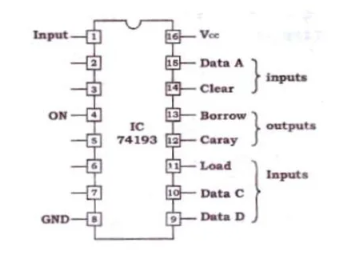
Figure 6: 74193 IC Pinout
The pinout layout of the 74193 IC is designed for maximum functionality. It includes input pins that allow users to preset the counter to start from a specific value, which is ideal for custom applications that require specific initial states. Output pins provide real-time feedback on the current count, making it easy to monitor or integrate the counter into larger systems that need live updates. A notable feature of the 74193 IC is the ripple carry output pin. This pin makes it easy to expand the counter's capacity by connecting (or cascading) multiple ICs. By using this feature, you can build high-order counters that handle larger counts, which is suitable for more advanced digital systems that require higher precision or larger counting ranges.
Using the IC 74193 to Make an Up/Down Counter
The IC 74193 is a versatile component used to build flexible counting circuits that can be customized for a wide range of applications. At its core, it operates reliably by connecting pin 16 to Vcc, ensuring a stable power supply. This connection is used for maintaining consistent operation in any system. The IC 74193 is designed with several input pins that allow for configuring various operational modes. One of the key features is its active-low parallel load input, which gives users the ability to start counting from any preset value. This feature is particularly useful when precise control over the counting sequence is required, as it allows the counter to jump to a specific value before starting the count.
A major advantage of the IC 74193 is its ability to easily switch between up and down counting modes. This can be done by making simple adjustments to the relevant pins. The ability to toggle between these modes without complicated configurations makes the IC highly flexible, enabling it to handle both basic and more complex counting tasks with ease.
Comparing Up Counters and Down Counters
Up counters and down counters serve different purposes based on their counting directions. An up counter begins at zero and increments to a set limit, making it well-suited for tasks that require tracking progress in a forward sequence. Examples include applications like time tracking or event sequencing, where each step moves upward in a linear fashion until a target value is reached.
On the other hand, a down counter starts at a defined maximum value and counts downward to zero. This type of counter is particularly useful in scenarios where you need to track a process in reverse. Common uses include countdown timers, where the remaining time is tracked as it decreases, or resource tracking, where you monitor how much of a resource is left as it is consumed.
Pros of Up/Down Counters
Up/down counters are highly valued for their simple design and synchronous operation, making them beneficial in systems that require quick and reliable counting. Their ability to count both up and down ensures flexible control, which is especially useful in applications where timing precision and fast responses are settling. Whether used for tracking events, timekeeping, or managing resources, these counters provide a straightforward and effective solution in a variety of digital systems.
Their design allows for smooth and predictable transitions between states, making them ideal for real-time applications. For example, they are commonly used in event counters, timers, or systems that need sequential counting in either direction, such as in industrial automation or digital clocks.
Cons of Up/Down Counters
Despite their strengths, up/down counters can face challenges at higher speeds. As the clock speed increases, propagation delays become more noticeable, which can lead to counting errors. These delays occur because the signal takes longer to move through each stage of the counter, reducing the accuracy of the system’s timing, especially in high-speed environments.
Another limitation arises as the bit size of the counter grows. Larger counters, which handle higher numbers, add complexity to the system. This increase in complexity can introduce synchronization issues or inaccurate counts, particularly when multiple counters are connected in a larger digital circuit. Systems that rely on precise synchronization across several counters, such as large-scale digital systems, may experience glitches or inaccuracies if the design is not carefully managed.
Uses of Up/Down Counters
Up/down counters are widely used across many industrial and technological applications because of their ability to count in both directions.
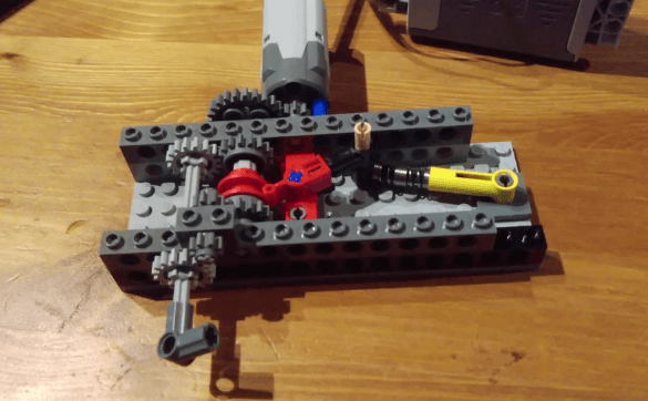
Figure 7: Auto-Reversing Mechanisms
One of the most significant uses of up/down counters is in auto-reversing mechanisms. In systems like conveyor belts or motor control, these counters enable bidirectional counting, allowing precise management of mechanical movements. For example, they ensure that machines can switch directions smoothly when needed, enhancing control over production processes.

Figure 8: Time and Signal Management
Up/down counters also play a major role in clock division circuits, where they manage time intervals to keep digital signals properly timed. In these systems, the counter divides the clock signal into smaller intervals, ensuring the entire circuit operates in sync. This is serious in digital devices that rely on accurate signal timing for proper functioning, such as processors or communication systems.
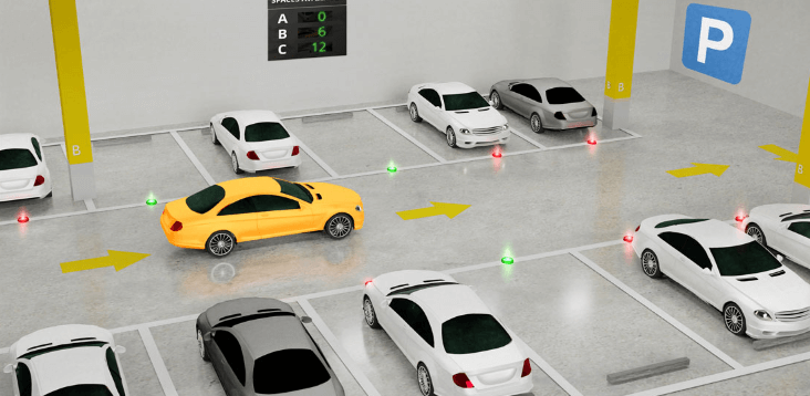
Figure 9: Vehicle Parking Systems
Another practical application is in vehicle parking systems, where up/down counters keep track of available parking spaces. Every time a car enters or exits, the counter adjusts the count to reflect the number of open spots. This automatic tracking improves space management and enhances the overall efficiency of parking facilities by providing accurate, real-time data on occupancy levels.
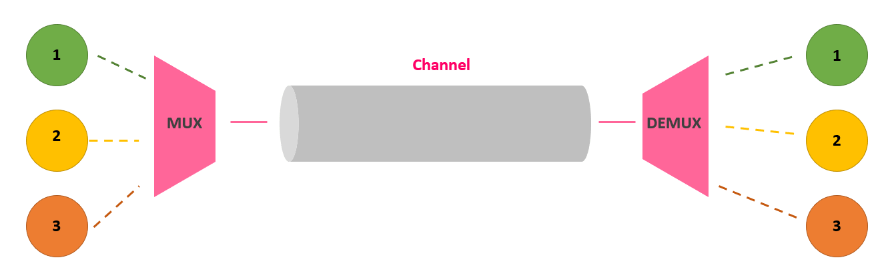
Figure 10: Frequency Division in Digital Electronics
In the field of digital electronics, up/down counters serve as frequency dividers, breaking down an input frequency into smaller, more manageable ones. This is especially significant in signal processing and communication systems, where different components require precise frequency control. By modulating input frequencies, these counters ensure smooth operation across devices that rely on accurate signal timing and modulation.
Conclusion
Throughout the article, the complexity and versatility of up/down counters have been thoroughly analyzed, showcasing their useful role in digital circuit design. The detailed exploration into various models, such as the 74193 IC, highlights the adaptability and precision these components offer to digital systems. By comparing up and down counters, the discussion emphasizes their specific advantages in diverse applications, from simple event counting to complex frequency division. In addition, the article addresses potential limitations, such as propagation delays and synchronization challenges, providing insight into effective design considerations that can enhance system reliability. The expanded applications section reaffirms the counters' requisite utility in precision control and signal management, proving that up/down counters are foundational to the advancement and efficiency of contemporary technological infrastructures. This detailed examination not only underscores the operational nuances of up/down counters but also their significant impact on the design and functionality of modern digital systems.
Frequently Asked Questions [FAQ]
1. What is up down counter 74193?
The 74193 is a specific type of integrated circuit (IC) designed as a synchronous up-down counter. It can count in both directions: incrementing (up) and decrementing (down). It features a 4-bit binary output and can be set up to count in any sequence within its 4-bit range. Operators typically use it in applications where reversible counting is required, such as in digital clocks or event counters in industrial systems.
2. What is up down counter using IC 74192?
The IC 74192 is another model of a synchronous up-down counter. Unlike the 74193, the 74192 is designed to count up or down through a decade (0 to 9 or 9 to 0) and is thus a decade counter. It's used where counts need to be displayed or calculated in decimal rather than binary form, such as in calculators or digital meters.
3. How does an up-down counter work?
An up-down counter operates by changing its state with each pulse from a clock input, counting up or down depending on the mode selected. Each pulse causes the counter's output to either increment or decrement by one unit. In practical applications, technicians might use these counters to measure frequency, and time intervals, or determine the position in mechanical systems by tracking the number of forward or reverse movements.
4. What is the IC number of up down counter?
Common IC numbers for up-down counters include 74193 and 74192, as discussed above. These numbers are part of the 7400 series of digital logic ICs, which indicates they are designed for digital counting tasks among other functions.
5. What is IC used in counters?
Integrated circuits (ICs) used in counters include a variety of types based on the counting needs. Commonly used ICs are the 74193 and 74192 for binary and decimal counting, respectively. Others might include the 4029, which is a programmable up-down counter, suitable for more complex applications where preset counting limits and multiple counting modes are needed. In practical scenarios, such as manufacturing lines or digital systems, these ICs help maintain precise counts of operations or objects.
About us
ALLELCO LIMITED
Read more
Quick inquiry
Please send an inquiry, we will respond immediately.

Exploring the MC34063ADR2G Switching Regulator: Functions, Features, and Uses
on September 21th
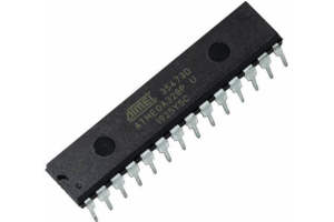
ATMEGA328P Microcontroller Overview
on September 20th
Popular Posts
-

What is GND in the circuit?
on January 1th 2915
-

RJ-45 Connector Guide: RJ-45 Connector Color Codes, Wiring Schemes, R-J45 Applications, RJ-45 Datasheets
on January 1th 2476
-

Fiber Connector Types: SC Vs LC And LC Vs MTP
on January 1th 2064
-

Understanding Power Supply Voltages in Electronics VCC, VDD, VEE, VSS, and GND
on November 8th 1854
-

Comparison Between DB9 and RS232
on January 1th 1749
-

What Is An LR44 Battery?
Electricity, that ubiquitous force, quietly permeates every aspect of our daily lives, from trivial gadgets to life-threatening medical equipment, it plays a silent role. However, truly grasping this energy, especially how to store and efficiently output it, is no easy task. It is against this background that this article will focus on a type of coin cell battery that may seem insignificant on the...on January 1th 1702
-

Understanding the Fundamentals:Inductance Resistance, andCapacitance
In the intricate dance of electrical engineering, a trio of fundamental elements takes center stage: inductance, resistance, and capacitance. Each bears unique traits that dictate the dynamic rhythms of electronic circuits. Here, we embark on a journey to decipher the complexities of these components, to uncover their distinct roles and practical uses within the vast electrical orchestra. Inductan...on January 1th 1647
-

CR2430 Battery Comprehensive Guide: Specifications, Applications and Comparison to CR2032 Batteries
What is CR2430 battery ?Benefits of CR2430 BatteriesNormCR2430 Battery ApplicationsCR2430 EquivalentCR2430 VS CR2032Battery CR2430 SizeWhat to look for when buying the CR2430 and equivalentsData Sheet PDFFrequently Asked Questions Batteries are the heart of small electronic devices. Among the many types available, coin cells play a crucial role, commonly found in calculators, remote controls, and ...on January 1th 1530
-

What Is RF and Why Do We Use It?
Radio Frequency (RF) technology is a key part of modern wireless communication, enabling data transmission over long distances without physical connections. This article delves into the basics of RF, explaining how electromagnetic radiation (EMR) makes RF communication possible. We will explore the principles of EMR, the creation and control of RF signals, and their wide-ranging uses. The article ...on January 1th 1519
-

CR2450 vs CR2032: Can The Battery Be Used Instead?
Lithium manganese batteries do have some similarities with other lithium batteries. High energy density and long service life are the characteristics they have in common. This kind of battery has won the trust and favor of many consumers because of its unique safety. Expensive tech gadgets? Small appliances in our homes? Look around and you'll see them everywhere. Among these many lithium-manganes...on January 1th 1496
HOT Part Number
-
10073599-008LF
Amphenol ICC (FCI)
CONN RCPT HSG 8POS 2.00MM
MJD32CTM
Fairchild Semiconductor
TRANS PNP 100V 3A TO252-3
ACMD-6003-TR1
Broadcom Limited
RF DUPLEXER 1.75/1.84GHZ 8VQFN
NCS12S1215C
Murata Power Solutions Inc.
DC DC CONVERTER 15V 12W
2225SC473MAT1A
KYOCERA AVX
CAP CER 0.047UF 1.5KV X7R 2225
SA13CA-E3/73
Vishay General Semiconductor - Diodes Division
TVS DIODE 13VWM 21.5VC DO204AC
AD808-622BR
Analog Devices Inc.
IC RECEIVER 16SOIC
M41ST85WMX6TR
STMicroelectronics
IC RTC CLOCK/CALENDAR I2C 28SO
CD74HC4040E
Texas Instruments
IC BINARY COUNTER 12-BIT 16DIP
74F04SJ
Fairchild Semiconductor
IC INVERTER 6CH 1-INP 14SOP
2N3906G
onsemi
TRANS PNP 40V 0.2A TO92
SMCJ36CA
Taiwan Semiconductor Corporation
TVS DIODE 36VWM 58.1VC SMC
LTM9010IY-14#PBF
Analog Devices Inc.
IC ADC 14BIT PIPELINED 140BGA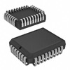
AT49F001T-12JC
Microchip Technology
IC FLASH 1MBIT PARALLEL 32PLCC
160-10-314-00-001101
Preci-Dip
CONN HDR DIP SLOT 14POS GOLD
TMS320C6748EZCED4
Texas Instruments
IC DSP FIX/FLOAT POINT 361NFBGA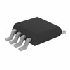
MIC2145BMM
Microchip Technology
IC REG MULTI CONFG ADJ 8MSOP
HA4344BCP
Harris Corporation
4X1 VIDEO XPOINT SWITCH -
C2220C104J1GACTU
KEMET
CAP CER 0.1UF 100V C0G/NP0 2220
LMV710IDBVR
Texas Instruments
IC OPAMP GP 1 CIRCUIT SOT23-5
LTC2175IUKG-14#TRPBF
Analog Devices Inc.
IC ADC 14BIT PIPELINED 52QFN
S908GZ60E1MFAE
NXP USA Inc.
IC MCU 8BIT 60KB FLASH 48LQFP
TW8804-LC3-GR
Renesas Electronics America Inc
IC VIDEO LCD CONTROLLER 160LQFP
MBR1645
onsemi
DIODE SCHOTTKY 45V 16A TO220-2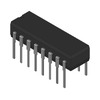
CD54AC257F3A
Harris Corporation
MUX, AC SERIES
RJK0346DPA-00#J0
Renesas Electronics America Inc
MOSFET N-CH 30V 65A 8WPAK
80716300000
Littelfuse Inc.
FUSE BOARD MOUNT 6.3A 300VAC RAD
SN74AHC2G04HDCTR
Texas Instruments
INVERTER 3-ELEMENT CMOS 8PIN SSO
MP38116DQ-LF-Z
Monolithic Power Systems Inc.
IC REG BUCK SYNC 5.5V 4A
ISL6207CB
Renesas Electronics America Inc
IC GATE DRVR HALF-BRIDGE 8SOIC
UMK105CG5R6BW-F
Taiyo Yuden
CAP CER 5.6PF 50V C0G/NP0 0402
MPX2100AP
NXP USA Inc.
SENSOR 14.5PSIA 0.19" .04V
SN65HVD256D
Texas Instruments
IC TRANSCEIVER HALF 1/1 8SOIC
MIC5159BM6
Micrel Inc.
IC REG LINEAR MICROCAP LDO REG
BD3814FV-E2
Rohm Semiconductor
IC AUDIO SIGNAL PROCESSR 40SSOPB
GRM32CR72A105KA35L
Murata Electronics
CAP CER 1UF 100V X7R 1210 -
BZX84B39-7-F
Diodes Incorporated
DIODE ZENER 39V 350MW SOT23
ISL83385ECA
Renesas Electronics America Inc
IC TRANSCEIVER FULL 2/2 20SSOP
VI-JW4-MW
Vicor Corporation
DC DC CONVERTER 48V 100W
MP020A-5GS-Z
Monolithic Power Systems Inc.
IC OFFLINE SWITCH FLYBACK 8SOIC
RT1206DRD07750RL
YAGEO
RES SMD 750 OHM 0.5% 1/4W 1206
1N2993A
Microchip Technology
DIODE ZENER 43V 10W DO213AA
CD74HC597M
Harris Corporation
PARALLEL IN SERIAL OUT
GRM022R60J224ME14L
Murata Electronics
CAP CER 0.22UF 6.3V X5R 01005
XCVU13P-2FHGB2104E
AMD
IC FPGA 702 I/O 2104FCBGA
8V97051NLGI8
Renesas Electronics America Inc
IC CLOCK GENERATOR 32VFQFPN
VE-221-EW
Vicor Corporation
DC DC CONVERTER 12V 100W
CAT25256XE
onsemi
IC EEPROM 256KBIT SPI 8SOIC
PIC16F872-I/SO
Microchip Technology
IC MCU 8BIT 3.5KB FLASH 28SOIC
UCC28C45P
Texas Instruments
IC REG CTRLR MULT TOPOLOGY 8DIP
BD71631QWZ-EVK-001
Rohm Semiconductor
EVAL BOARD FOR BD71631
MBR12035CT
GeneSiC Semiconductor
DIODE MODULE 35V 120A 2TOWER
BCM5328SA1KQMG
Broadcom Limited
ENTERPRISE SWITCHING
12061A100DAT2A
KYOCERA AVX
CAP CER 10PF 100V NP0 1206